Build Thread: Burni

SPF40plus

Member
Okay, so the turbo project is starting properly this weekend. The 6bg1 in standard form is 120kw and 431Nm. Yawn.

After way too much research and time hunting down parts, this is what I've put together:
  1. HX35w turbo
  2. V-band clamps for turbine and compressor housings
  3. V-band flanges
  4. Manifold of a 6bg1tq
  5. Lots of hose clamps
  6. Lots of silicone bends and tube
  7. 316 2.5" tube for the intercooler pipe
  8. 316 3" tube for the exhaust dump pipe
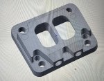
  9. 30mm 316 plate for t4 to T3 adaptor (turbo is T3 and manifold is t4)
  10. 316 5" tube for snorkel
  11. 316 4" tube for air filter to turbo
The HX35w has a twin scroll turbine, and the manifold is divided too. I'm hoping this results is good throttle response and 8psi of boost by 1200rpm. It should.

If you are looking at a turbo conversion using the Hx35, the compressor housing is huge. You really need to consider if you have enough room. The first part of this job for me is working out how to make it fit.

I still need to get an intercooler and the oil supply and return lines, but I'll get these made once everything else is fitted.

I'm still trying to find someone with a dyno that's large enough who will do a run pre conversion. All the tuning guys seem to be a bit precious about old trucks, and seem to only be interested if they can sell you a chip or remap. This is a problem I wasn't expecting to have if I'm honest.
 

Ultimark

Active member
The extended truck is a Hino 921, the most interesting part was the front axle weight change.

With the 800mm extension being where it is, the good news was to put a crane in and run it off the PTO. The bad news was the increased weight on the front axle as a result of the rear axle now being further away, which meant that the addition of a crane cannot be done as the calculations suggest the front axle will be over its limit, or so close it doesn't matter. Smaller and lighter cranes, are now being looked at but I believe it will be a marginal thing if they succeed.

The Hino belongs to a distant relative, very distant... :oops:

Mick.
 

g_m

New member
"The bad news was the increased weight on the front axle as a result of the rear axle now being further away, which meant that the addition of a crane cannot be done as the calculations suggest the front axle will be over its limit, or so close it doesn't matter. Smaller and lighter cranes, are now being looked at but I believe it will be a marginal thing if they succeed."
Yes, cranes ca be heavy. I'm at the front axle limit myself (MB 1525).
 

SPF40plus

Member
The extended truck is a Hino 921, the most interesting part was the front axle weight change.

With the 800mm extension being where it is, the good news was to put a crane in and run it off the PTO. The bad news was the increased weight on the front axle as a result of the rear axle now being further away, which meant that the addition of a crane cannot be done as the calculations suggest the front axle will be over its limit, or so close it doesn't matter. Smaller and lighter cranes, are now being looked at but I believe it will be a marginal thing if they succeed.

The Hino belongs to a distant relative, very distant... :oops:

Mick.
Wow, why wasn't the calculation done prior to the extension?
 

SPF40plus

Member
If I'm honest it's something most people don't even think about. With Burni the quoted kerb mass on the front is 2,700kg (5,940lb) with 10 litres (2.5 gallons) of fuel. The axle capacity is only 4,700kg (10,340lb), so there is only 2,000 kg of load capacity.

When you add all the bits and pieces on its easy to go over.

The give away with the fire body was the tank was almost a metre back from the headboard. It would have been way more useful further forward.
 

Dansale

New member
Sorry for straying OT, but about the small hino with the frame stretch...

Can't imagine driving one of those with that much weight on the front.
The brand new tray truck I recently drove had only 30mm to the front bump stops. Every freeway bridge expansion joint had the front bouncing off the stops, truck was empty!

Perhaps slide the rear axle forward, get some weight off the front axle? Bit of a hard situation to be in, for the owner! Good luck.
 

SPF40plus

Member
Ok, so time for an update.
I have spent too many hours jigging things to get the turbo to fit. But I can now confirm that it will fit without modifying the truck, or anything else. It will require a 30mm spacer, inclusive of the gaskets, and the compressor housing outlet has to point out over the tappet cover. Anything other than that and life gets really hard.

Here is the silhouette in place.
IMG_20230508_075320413_1683546108377.jpg

In the photo it looks like it's against the tunnel on the left, but there's a 20mm gap behind the heat shield. I need to find a way to keep the shield against the tunnel.

There is a large gap under the silhouette because the turbo manifold has a large platform to mount the turbo, and the adaptor will be on top of that.

IMG_20230504_161216288_HDR_copy_432x841.jpg
 

SPF40plus

Member
So a question for turbo nerds. If you are wondering if you are one, and you know what lb/min is used for then that's you.

Is it important for a turbo flange to be supported around the whole border, or can the support be slotted to get to the bolts/studs?

I'm looking at using something like this
IMG_20230508_181116_01_copy_800x622.jpg

The top is for a t3 flange and the bottom is for a t4 flange. The holes on the side are for thermocouples.

Will this create any issues? EDIT: What I'm concerned about is that there is insufficient shear strength on the studs holding the turbo down because I'm relying on the stud's ability to resist sideways deflection. The other concern is whether this creates a load that might crack the flange on the turbo (cast iron).

Any comments are welcome.

EDIT:
Here it is in context:
2023-05-09_11h37_18.png
 
Last edited:

Dansale

New member
Is it important for a turbo flange to be supported around the whole border, or can the support be slotted to get to the bolts/studs?

Which part do you want to slot? The actual flange on the exhaust housing? Or the adaptor?

Whatever you do, need to maintain very flat surface area for the gasket to seal against and enough stud clamping force to actually seal the gasket properly.
 

SPF40plus

Member
Which part do you want to slot? The actual flange on the exhaust housing? Or the adaptor?

Whatever you do, need to maintain very flat surface area for the gasket to seal against and enough stud clamping force to actually seal the gasket properly.
See images above.
 

Dansale

New member
When there's limited clearance and great difficulty to assemble the turbo to adaptor to manifold, have had some success with the following...
Try to assemble the whole thing on the bench then slip manifold onto prefitted head studs.
If not possible, then using prefitted studs and nuts in the adaptor plate can help.
Sometimes twelve point (double hex) headed bolts and nuts can help, don't be scared to custom grind ring spanners and make thin sockets to get them into the turbo flange nuts. Never easy though, good luck mate!
 

Dansale

New member
Thanks for the edit, my reply above is probably irrelevant now.

Some random ideas from easiest to worst...

Use metric fine pitch studs, for greater shear strength. But doing that creates more clamping pressure on that unsupported flange ear.... Hmmm.

Drill out the turbo flange holes a bit and use standard metric studs, but with precision machined steel sleeves slipped on, to locate the stud central relative to the flange holes.... Prevent the turbo walking around / stud shear, perhaps.

Stud then plug weld the adaptor to the manifold permanently. Use a normal t3 footprint flange for the turbo.

Not sure if useful, just throwing mud here...
 

SPF40plus

Member
Whatever you do, need to maintain very flat surface area for the gasket to seal against and enough stud clamping force to actually seal the gasket properly.

I'm not concerned about enough clamping force, I'm concerned about snapping the corners off the turbo flange, or them cracking over time under load after 500-1000 thermocycles. I think there is enough surface area for the gasket, especially since they are usually beaded sheet metal gaskets, so they only need the width of the bead to be flat on the flanges above and below.

Also, most of the commercially available adaptors have less surface area for the gasket than this one.

What do you think about the thickness? Should I be cutting out any unnecessary mass to try and match the heating and cooling rate of the manifold and the turbo housing - does this matter at all?
 

Dansale

New member
About the unsupported ears on the turbine housing.... I have no direct experience here, but I imagine you'd want to avoid doing that. If they broke off in the outback, you'd be in trouble.

Id be guessing on the heat expansion thing

Id probably lean towards a plain style adaptor plate without those cutouts and Tig weld it to the manifold. (Using the correct pre and post heating techniques and correct nickel? Rod of course)
Then attach turbo in the usual manner.
 

Forum statistics

Threads
188,251
Messages
2,904,521
Members
229,805
Latest member
Chonker LMTV
Top