You are using an out of date browser. It may not display this or other websites correctly.
You should upgrade or use an alternative browser.
You should upgrade or use an alternative browser.
Build Thread: Burni
- Thread starter SPF40plus
- Start date
Thanks for the info.I just used a piece of 3/4 plate to make my T3- T4 adapter. The holes where it bolts to the T4 side are tapered /Countersunk and I use View attachment 777812 in the appropriate size.
The T3 holes are threaded and studs are used. The surfaces for the gaskets were draw filed flat.
What size are the heads on those countersunk screws? I confirmed today that the copper lock nuts are 14mm across the faces and 16.1 OD for M10x1.5.
DIN bolts are, but there are others, smallest are 15.85 to 16.13mmM10 metric csk cap screws to DIN 7991 have a head dia of 2xD, so 20mm. I wonder if our Aussie screws are to that standard?
Last edited:
Ok, I have been working with BLC392 (Wicked Turtle) on the adaptor and he has prototyped his (same truck, manifold, and turbine housing).
The question now is what thermocouples to use, and what to connect them to. So three questions:
The question now is what thermocouples to use, and what to connect them to. So three questions:
- Have you used a digital dash, if so do you like it or hate it?
- Have you built a digital dash using Rasberry Pi, Arduino or similar, and if so are you happy with it?
- Have you used a Power Tune, Oneguage, JRP 14 in 1 or any similar products?
With the turbo and intercooler now waiting for some new engine and fuel parts before I start the install, I went looking for a way to read sensor data from 2 EGTs, a boost gauge, and a temp sensor for the intake. A good set of analogue gauges can be had for approximately $1,000 and about 220mm (9") to 300mm (12") of dash space (if lined up next to each other).
This is a lot of real estate and a lot of holes to put in the dash. Despite the size of the truck the dash space is actually really limited.
I didn't get any responses to my previous query about digital gauges, but after researching them further, most only really support OBDII unless you buy a bunch of other stuff to get analogue data converted to digital signals. Which is costly and boring.
I'd already bought a raspberry pi to monitor the tanks and solar for the camper, so decided to try building a digital dashboard with it.
My requirements for the dash are that it:
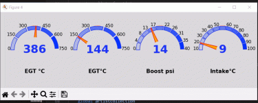
The biggest question I had was whether I could build a digital dash that updated in real time, and showed the graphs with useful data. Here is where it is a presently - the dials move around randomly because I have a sensor emulator running that simply generates random numbers.
Daytime Screen:

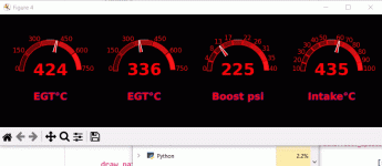
Night time screen (I know the numbers and dial don't match on this):

You will see on the bottom of the above image that the CPU usage is shown for Python. The original concept that I coded was only capable of 1-2 second intervals (refresh) because it was rendering the whole screen each time. It maxed out the Raspi's processor and crashed at full noise. The program now uses blitting, so the only data being updated on the screen is the needle, and the digital readout, the remainder is set at initial start-up.
If you are wondering why the two different screens, the red readout can be on at full brightness at night and only marginally reduce your night vision, but it is harder to see during the day, especially with sunlight on the screen. The daytime screen uses blue with light grey to give a high contrast image without unnecessary glare (such as from white background). There is an interesting discussion here if you want some more information: https://ux.stackexchange.com/questi...sitivity,produces the highest visual contrast. I tried the black with yellow, but where you have a screen that reflects light from its surroundings, yellow seems to be affected more than the grey.
I'll post an update once I get some sensors connected, and some physical buttons and a potentiometer connected to control dash functions and screen brightness respectively.
This is a lot of real estate and a lot of holes to put in the dash. Despite the size of the truck the dash space is actually really limited.
I didn't get any responses to my previous query about digital gauges, but after researching them further, most only really support OBDII unless you buy a bunch of other stuff to get analogue data converted to digital signals. Which is costly and boring.
I'd already bought a raspberry pi to monitor the tanks and solar for the camper, so decided to try building a digital dashboard with it.
My requirements for the dash are that it:
- is readable day or night
- is able to show data for at least 4 sensors
- is powered by the cab electrical circuit
- turns on when the ignition is switched to Acc or On
- turns off when the ignition is switched to off without killing it
- logs all data coming in, and saves to an externally accessible drive
- be updatable/upgradable
- be repairable and have reasonable component support/availability
- not be insanely expensive
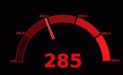
- getting a real time graph to display data was randomly difficult to find, examples exist but they are generally developed by individuals for their race cars, and most also use OBDII because that is what people are playing with: result - I've written my own in Python (after relearning Python) and using the Matplotlib and Numpy libraries, which are both open source. The image above is the test dial.
- I'm not sure yet if I'm going to use a small ultrawide screen that is made specifically for raspberry pi, or something else, but am tentatively looking at a 7.9 inch Waveshare capacitive touchscreen.
- I need a 24v-5v dc-dc converter to power the Raspi
- I found a project done by Everlanders on youtube, which you should look at if this is something you are interested in, they have a video on controlling the starting and shutting down the Raspi. I'll be doing something similar using an Optocoupler.
- there needs to be either a direct connection to the battery, or an inline battery capable of powering the Raspi until it shuts down, otherwise it is likely that simply turning off the Raspi will cause it to fail. There are RAID controller backup batteries for servers, and I'm trying to find one of these to see if I can use that, unfortunately it looks like most operate on 12v.
- I bought an SD reader breakout board and 32Gb SD card for the Raspi to save log data to.
- I've bought some ADC (analogue to digital controllers) to test, and some EGT amplifiers, as EGT voltage is produced by the elements in the thermocouple when heated, unlike other sensors that commonly act as a variable resistor that operate between 0 and 5v. The voltage from the thermocouple is very small and the magnitude of difference between a temperature of 100 degrees versus 800 degrees is less than 1v (4mV to 34mV). Testing these to destruction/failure is going to be interesting.
- The components for the Raspi are available in every state and territory, so waiting for a part should not be as bad as for some of the other options. The downside of course, is that if you make it you have to maintain it.
- So far the costs are looking like AU$450 to AU$650 depending on options. It is worth noting that you can get the people at Onegauge.com to make a custom board, or there are units that can read analogue sensors available from Powertune (Australia) and from Just Race parts (Australia) but the latter is the JRP 14 in 1, and the screen on this is very small (and I'm too old for that). I priced up a full set up with Onegauge and it was in excess of $4k. It was awesome, but for that price, buying a second as a backup makes it really expensive as an option.
The biggest question I had was whether I could build a digital dash that updated in real time, and showed the graphs with useful data. Here is where it is a presently - the dials move around randomly because I have a sensor emulator running that simply generates random numbers.
Daytime Screen:

Night time screen (I know the numbers and dial don't match on this):

You will see on the bottom of the above image that the CPU usage is shown for Python. The original concept that I coded was only capable of 1-2 second intervals (refresh) because it was rendering the whole screen each time. It maxed out the Raspi's processor and crashed at full noise. The program now uses blitting, so the only data being updated on the screen is the needle, and the digital readout, the remainder is set at initial start-up.
If you are wondering why the two different screens, the red readout can be on at full brightness at night and only marginally reduce your night vision, but it is harder to see during the day, especially with sunlight on the screen. The daytime screen uses blue with light grey to give a high contrast image without unnecessary glare (such as from white background). There is an interesting discussion here if you want some more information: https://ux.stackexchange.com/questi...sitivity,produces the highest visual contrast. I tried the black with yellow, but where you have a screen that reflects light from its surroundings, yellow seems to be affected more than the grey.
I'll post an update once I get some sensors connected, and some physical buttons and a potentiometer connected to control dash functions and screen brightness respectively.
Thanks for the tip. I was thinking of doing this in a seperate process and then deliver a list or tuple to the main program. With no new data a gauge's features will not be rewritten. I can independently control the refresh rate of each sensor then too. With priority going to the EGTs.If you are not doing it already, you can also check to see if a value has changed and only update it if it has.
Is there a better way to do it?
SkiFreak
Crazy Person
How long is a piece of string?Is there a better way to do it?
There is not really a simple answer to that question, as there are so many possible variants.
A possible path could be to use a screen that has it's own graphics processor, which would mean your RPi would not be doing all of the processing.
I should also add that this forum is probably not the best one for getting solutions for electronics projects.
SkiFreak
Crazy Person
I'm definitely not what I would consider to be a "programmer", but I have definitely dabbled in this area.
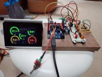
Here is a little ongoing project of mine, which is a tank monitor for my camper, based on an Arduino and using a 4D Systems screen.
All of the graphics are done by the screen's processor and the Arduino simply updates the changes.

Here is a little ongoing project of mine, which is a tank monitor for my camper, based on an Arduino and using a 4D Systems screen.
All of the graphics are done by the screen's processor and the Arduino simply updates the changes.

Awesome.I'm definitely not what I would consider to be a "programmer", but I have definitely dabbled in this area.
Here is a little ongoing project of mine, which is a tank monitor for my camper, based on an Arduino and using a 4D Systems screen.
All of the graphics are done by the screen's processor and the Arduino simply updates the changes.
View attachment 780798
Do you have a background in C/C++? How does the integration work between your Arduino and this screen? is there a driver that causes the graphics processing to be performed by the screen rather than the Arduino? I know how this works on windows but not sure in this case.
I mainly use VB.net and C#, but thought I'd try Python again especially for this project because I don't have to distribute anything or compile the code and sign it. I am also doing this so I can teach my kids how to code, and python will let them start without having to understand IDEs, compiling, and all the other machinery that goes into writing software.
BTW I read a lot of your website a few years ago when I first started thinking about this project.I'm definitely not what I would consider to be a "programmer", but I have definitely dabbled in this area.
Here is a little ongoing project of mine, which is a tank monitor for my camper, based on an Arduino and using a 4D Systems screen.
All of the graphics are done by the screen's processor and the Arduino simply updates the changes.
Similar threads
- Replies
- 27
- Views
- 3K
- Replies
- 2
- Views
- 388
- Replies
- 0
- Views
- 168
- Replies
- 26
- Views
- 4K


