Off track, yes, may mean the need or another thread. See signature for further discussion on the digital dash build. ?This is getting a bit off track, but if you want your kids to learn programming, the Arduino platform is a excellent place to start.
Lots of cheap hardware and modules available on eBay and the Arduino IDE makes uploading code very simple.
I sent you a PM.
You are using an out of date browser. It may not display this or other websites correctly.
You should upgrade or use an alternative browser.
You should upgrade or use an alternative browser.
Build Thread: Burni
- Thread starter SPF40plus
- Start date
Time for an update.
While cleaning out the unbelievable mess that I had made inside the cab this morning (electrical, welding, parts, etc), I found my notes on the central locking system that I installed a few months ago. Of course this got rained on at some point, so is looking worse for wear. I'm posting this up in case you are interested in installing a 24v central locking system, and so I have a record of it.
The system comprises:
The security system has a number of features including immobilisation and audible alarm, but I'm not going to discuss these here. They are substantially independent of the keyless entry anyway.
The objective for the setup is:
As a general description, the M24 sends a positive signal on the blue wire to lock, and a positive signal on the green wire to unlock with the respective button press. However, if it suits your purposes you can reverse this, but note the lock/unlock button press also triggers things like setting the alarm state to on, and others if you are using those features. The other thing to note is that in each case the other wire needs to act as a ground (more on this later).
I have connected the blue wire (from M24) to pin 85 of one relay (I'll refer to this as the Lock Relay) and the green wire (from M24) to pin 85 of the other relay (I'll refer to this as the Unlock Relay).
The third relay is use to control the switching and provide an alternative ground for each circuit (I'll refer to this as the Ground Relay). On this relay Pin 30 is connected to ground (be careful with this). The image below shows the general arrangement:
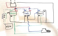
On the left hand side, note the two diode symbols. You have to do this (or something else) so that the control circuit in the M24 will work - it allows the circuit to close in each direction.
The image below shows Lock button press (red dashed line for positive, black dashed line for negative):
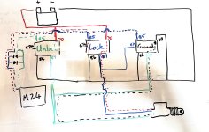
The following image shows unlock button press:

While cleaning out the unbelievable mess that I had made inside the cab this morning (electrical, welding, parts, etc), I found my notes on the central locking system that I installed a few months ago. Of course this got rained on at some point, so is looking worse for wear. I'm posting this up in case you are interested in installing a 24v central locking system, and so I have a record of it.
The system comprises:
- Mongoose M24 Vehicle security system (including keyless entry with two fobs);
- 4x Mongoose 24v two wire door motors (there are no longer any master motors available from Mongoose, Rhino, or anyone else in Australia);
- 3x 5 pin 24v relays (i used FRC7C-SR-1 units from Jaycar):
- Pin 85 = trigger;
- Pin 87 = normally open output;
- Pin 87a = normally closed output;
- Pin 30 = positive supply (battery/fuse block);
- Pin 86 = ground;
- 2x inline blade fuse holders;
- 2x high amperage diodes;
- Miscellaneous fittings and heat shrink - the relays use male blade fittings.
The security system has a number of features including immobilisation and audible alarm, but I'm not going to discuss these here. They are substantially independent of the keyless entry anyway.
The objective for the setup is:
- Enable keyless entry (by unlocking all doors);
- Enable automatic relocking if vehicle isn't accessed, which also means that a mistaken button press doesn't leave the vehicle unlocked;
- Use the 24v electrical system of the truck, not a 12v sub system (the key reason for this is to minimise battery drain over long periods of non-use);
- Allow for the external battery disconnect to be used, and allow for instant access to be possible when the switch is closed (and reimpose the alarm at the same time).
As a general description, the M24 sends a positive signal on the blue wire to lock, and a positive signal on the green wire to unlock with the respective button press. However, if it suits your purposes you can reverse this, but note the lock/unlock button press also triggers things like setting the alarm state to on, and others if you are using those features. The other thing to note is that in each case the other wire needs to act as a ground (more on this later).
I have connected the blue wire (from M24) to pin 85 of one relay (I'll refer to this as the Lock Relay) and the green wire (from M24) to pin 85 of the other relay (I'll refer to this as the Unlock Relay).
The third relay is use to control the switching and provide an alternative ground for each circuit (I'll refer to this as the Ground Relay). On this relay Pin 30 is connected to ground (be careful with this). The image below shows the general arrangement:

On the left hand side, note the two diode symbols. You have to do this (or something else) so that the control circuit in the M24 will work - it allows the circuit to close in each direction.
The image below shows Lock button press (red dashed line for positive, black dashed line for negative):

The following image shows unlock button press:

Hi everyone, it's been a long time since I posted anything. Apologies, but work, rain, flooding, and the project took over my life.
The good news is that we now have a truck to drive around. There have been a number of compromises and changes and some of the initial plans may be added later, but we'll see how it goes in field testing.
What we did:
1. Turbo
2. Winch
3. Tow bar
4. House/Camper semi permanently attached
5. Roof rack and brush bars
6. Paint
7. Cab interior
I'll post up some details on each in the coming week or two. Here it is:

Turbo:
First some background info:
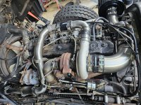
Turbo: Holset HX35W
Intercooler: Proflow 400x300x100
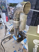
Pipework: 316L stainless steel 2.5" tube
Intake Pipe: 4" 316L tube with catchcan plumbed in and air compressor intake plumbed in.
We haven't spent enough time on the freeway at 90kph to give you useful feedback. But initial figures were 16psi boost, 380-450 *C egts.
On terrible outback sealed roads we are are generally travelling at 80-85kph.
On flat roads boost is 11 to 13 psi, AFR (which I know is not correct ) of 39.5 and egt of 360ish.
On a 4% incline boost rises to 15psi, AFR goes to 38.5, and egt to 450ish.
On 5% incline egt starts to climb and I back off once it gets to 500*C. I've got the wastegate set to 17psi.
For most 1km or less inclines of 5% I don't need to back off or change gears.
The fuel screw was out at three turns when we left, it's now at 2.25 and is more drivable and fuel economy is back down to 24 -26L/100 down from 35ish.
Just a note on EGTs: our pyrometer is in the adapter plate between the turbo and manifold (pre turbo) and as a sanity check i have looked at the temper colours of the parts of the exhaust system. The adapter has turned blue so has reached a temperature of 420 to 470 degrees C. If you plan to put a pyrometer in the dump pipe (post turbo) consider the EGTs you are getting carefully. Our dump pipe has barely turned light yellow, which indicates a temperature of 210-220 degrees C. The exhaust gas inside may be hotter, but this demonstrates the difference in placement of the pyrometer, and the heat your engine is actually being exposed to.
The power isn't the limiting factor now, its the suspension and load stability. The research for that has begun.


Winch:
The winch is a 20,000lb Runva Hydraulic unit. There was no PTO or pump on the truck so we had to fit one. The transmission in the truck is a MLD6D and Hydreco makes a PTO and pump for it.
The model numbers are:
PTO: PA371SEL11AOS
Pump: PUA75
We designed and built a mount for the winch using laser cut 12mm plate.
It slides inside the chassis and then there are external plates that bolt on.
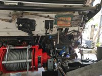

We decided to not compromise the strength of the bar and connection to the chassis, by cutting a notch for the steering box, so we took the steering box off and inserted the plate under it.
The bullbar had to be cut and modified to fit the winch, and we maintained the original bullbar eyebolts and cab lift safety switch.

The winch is a 20,000lb Runva Hydraulic unit. There was no PTO or pump on the truck so we had to fit one. The transmission in the truck is a MLD6D and Hydreco makes a PTO and pump for it.
The model numbers are:
PTO: PA371SEL11AOS
Pump: PUA75
We designed and built a mount for the winch using laser cut 12mm plate.

It slides inside the chassis and then there are external plates that bolt on.


We decided to not compromise the strength of the bar and connection to the chassis, by cutting a notch for the steering box, so we took the steering box off and inserted the plate under it.
The bullbar had to be cut and modified to fit the winch, and we maintained the original bullbar eyebolts and cab lift safety switch.

soaringpotato
Member
Great photos! Good to know about the pyrometer placement. I'll be fitting one of those here soon.
SkiFreak
Crazy Person
Something that I noted in your truck image is the cable weight bar on your winch (I think that is what it is).
My concern with this device would be when it comes to corrugations and the resulting vibrations, as this could have the potential of creating a wear point on the cable, where the two touch.
My concern with this device would be when it comes to corrugations and the resulting vibrations, as this could have the potential of creating a wear point on the cable, where the two touch.
Yeah, that may be a thing. I've been keeping an eye on it and no wear yet after 3,000km. We are due to do a service soon so I'll pull the bullbar and have a good look.Something that I noted in your truck image is the cable weight bar on your winch (I think that is what it is).
My concern with this device would be when it comes to corrugations and the resulting vibrations, as this could have the potential of creating a wear point on the cable, where the two touch.
A friend of mine has the same winch, and nothing to report after 10k.
Yep, 4.2t up front fully loaded.Those additions will definitely help with traction on your front wheels.
Yes used existing airbox, I cut off the stupid bend that the rubber elbow was attached to and welded a 4" ss tube to it.SPF40plus, excellent pics and thanks for updating us!!
Did you reuse the factory air box and filter assembly? Do I spy a modified snorkel there?
Could you tell us about the exhaust arrangement?
Are you happy with the driving manners of the current turbo setup?
Cheers mate
I made a 316 4" snorkel too.
There is 316L schedule80 but weld bends from the turbo to the exhaust brake. From the exhaust brake there is 3" 316L tube down to the flange (dump pipe) that the exhaust bolts to. The exhaust is steel with a teeny tiny muffler. It would have been better with no muffler because it is boring quiet
Driving manners is somewhat determined by the fuel screw. Doing 87k/h accellerating up a 5% gradient is satisfying. But with that said, it does lose boost after 2500rpm, and if you want more top end power then get the HE351 instead
It spools slower, but has a bigger blower so can deliver more top end flow.
snip..... it does lose boost after 2500rpm, and if you want more top end power then get the HE351 instead
It spools slower, but has a bigger blower so can deliver more top end flow.
Ah so does it hit 17psi lower in the rev range then die off up top?
Are you limited by EGT getting too high on big hills, do you have to back off the throttle to control EGT?
With the go faster pedal down you can hit 17psi from 1400 to 2500rpm. The wastegate is set to ~17.5 so it may otherwise be higher. From 2500 to 2700rpm boost falls to about 16psi.Ah so does it hit 17psi lower in the rev range then die off up top?
Are you limited by EGT getting too high on big hills, do you have to back off the throttle to control EGT?
I let the EGTs get to 550*c and then back off. That happens on 1km plus at 5 degree incline or larger inclines. Interestingly at 86kph (2500rpm) it stays cooler longer than at 80ish kph (2350rpm).
Similar threads
- Replies
- 27
- Views
- 3K
- Replies
- 2
- Views
- 391
- Replies
- 0
- Views
- 170
- Replies
- 26
- Views
- 4K
Forum statistics
Members online
- YukonMontanaTannerTrapper
- driller
- Mickey Bitsko
- mxdevon
- WKexpedition
- TravelTripper
- Outono
- GFC_Tremor
- MustacheMoto
- SDDiver5
- valcon1
- Jackem
- matimeo
- montechie
- dstefan
- keithlife
- mark5280
- Zeep
- Datsun Man2
- NOPEC
- Toasty
- gator70
- glen2480
- bjorn240
- GrantC
- ITTOG
- MR. ED
- freewayross
- Rockbridge
- IChaseCoues
- Slickrock Slim
- rruff
- 02955i
- MontanaMils
- ovrland6250
- brianpark
- SuperSingles
Total: 3,144 (members: 43, guests: 3,101)
