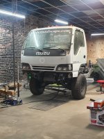
Cabover HMMWV Expedition Truck Project

shortbus4x4

Expedition Leader
Wow, amazing build you're doing. I used to drive and work on HMMWV for Uncle Sam when I was a young man. Never would imagine a cabover on one!
 

DzlToy

Explorer
This is a very interesting build. I have seen a 6BT on an engine stand and it isn't small, neither is an LCT1000. Is the current location where the GM 6.5 V8 was? It seems by looking at the pictures that the driveline is quite far back, which is great for weight balance, but terrible from a use of space standpoint (length). What was your reason for placing the engine so far back and what will you do with the forward "engine" space?
 
Last edited:

Jrheld

New member
Hi,
I am looking here on a kind of regular basis.
Unfortunately no news on the progress of your project since 3 month.
By the way, you only need a single support bearing on one of the steering cardan shafts, better rather close to the middle cardan hinge. Otherwise the System would be overdefined. (Is overdefined the proper English word ?)
Best Regards from Turky now
AloHa
Jakob
 

zioxkoa

Member
The reports of this truck's death have been greatly exaggerated ;)

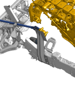
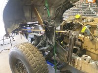
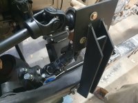
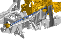
I've been really bad about posting updates on expo/social media, but it's been coming along. The steering is done and works great, compared to a stock Isuzu NPR it's actually less slop (and all the play is in the original HMMWV steering gear). I ended up modifying the routing to make for easier fabrication and eliminate an overdefined u-joint (noticed by a few of you). I also had the heim joint in the CAD mockups but ended up not using it in the end.
20230112-00h05m15s_grim.png20230112-00h05m32s_grim.png
20230112-00h05m44s_grim.png
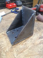
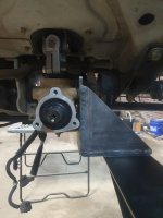
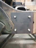
The angles on the rear 90 degree steering box were pretty crucial to keep all of the joints from binding, it needed a few degrees of both camber and toe. The front 90 degree box was more simple, it could be vertical with the slip joint going into the cab from there. I made both front and rear mounts with 1/4" steel and doubled up the motor mount bolts for the rear mounting point. With such a large lever arm I needed the base to be solid. All the steering shafts are 1" solid keyed steel rod and the u-joint yokes are spicer 1000 series (also used in SXS drivetrains).
20230128_235200.jpg20230210_214521.jpg20230121_200844.jpg20230128_104144.jpg20230529_191059.jpg

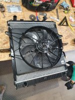
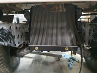
With the steering done, it was time to move on to planning all the cooling loops, hoses, radiators, air boxes etc. I spent a while trying to land on a happy medium of performance vs parts store availability. Luckily enough, an Isuzu NPR radiator still fits between my frame rails and doesn't stick down any further than the frame cross members, so I went with one of those. These should be easy enough to source in the future if I need to replace vs trying to fix a fully custom (but probably better performance) rad. With the distance between the radiator and engine I went with a Dorman electric fan that I've heard good things about, then some aftermarket radiators for the power steering and transmission coolers. I still need to make a shroud for the electric fan to completely cover the radiator...

20230429_140358.jpg20230609_233943.jpg

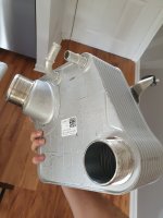
With the limited space and need for an intercooler, I decided to go with a water to air IC to have more flexibility with mounting and lower EGTs. Originally I was looking at aftermarket, however after some searching I found that the Ford 6.7 powerstroke has a water to air IC stock. So in the spirit of keeping parts easy to find and replaceable, I grabbed one of those.

For the air intake, I went with an air filter/intake combo from Donaldson meant for off-highway vehicles. I've seen some of the LMTV owners here and elsewhere use this type of intake and praise them, so I grabbed a 5" version with enough flow rate for the 6BT.

Ran out of space for pics again, continued below...
 

zioxkoa

Member
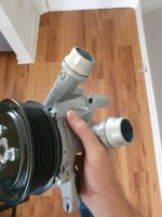
Going with a water to air IC means there's yet another coolant loop which also means there's another pump needed. I wasn't confident in how an electric pump would handle this kind of wear/tear, so I opted for the matching belt-driven water pump from a 6.7 powerstroke (also in the spirit of OEM replaceable parts). I got somewhat sidetracked trying to find the correct fitting for this pump (including 3d printing some that could work in a pinch), but eventually had luck with the Dorman 32mm heater hose connector.

20230420_121724.jpg20230420_121559.jpg

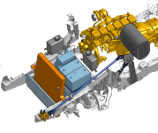
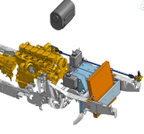
For starting batteries I decided to get a pair of group 31 AGMs (buy once cry once or something like that), then with all the "big" parts in hand I started to design how to place everything in the remaining room of the engine bay. CAD came in handy for this and it's almost where I'd like it, but it's still a work in progress.

20230616-02h09m53s_grim.png20230616-02h10m14s_grim.png
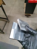
Meanwhile, with the radiator position and angle being mostly fixed I was able to start machining the mounts for it. Given the small space above it, the rad needs to sit back at a slight angle. After some time on the mill I had a pair of aluminum doorstops to do just that (you can also see them in the above post with the radiator in place). I'm still searching for just the right rubber bushings to place in these.

20230609_231109.jpg20230609_234514.jpg

So that's where this is at now. It's been mostly planning/design work and less fabrication lately, but hoping to get back to the fab work soon.
 

zioxkoa

Member
This is a very interesting build. I have seen a 6BT on an engine stand and it isn't small, neither is an LCT1000. Is the current location where the GM 6.5 V8 was? It seems by looking at the pictures that the driveline is quite far back, which is great for weight balance, but terrible from a use of space standpoint (length). What was your reason for placing the engine so far back and what will you do with the forward "engine" space?
The engine is in the stock HMMWV 6.5 location yes, there is a differential and frame crossmember ahead of it which limits how far forward it can go without raising it another foot. I opted to go with the lower and further back position to keep the CoG low, but also because it's much easier from a fabrication perspective. The driveline is definitely further back compared to other cabovers, but it isn't unreasonable when you model the living space and where the floor lands. The frame rails having a drop in the center also makes it look like it protrudes into the living space more than it does in reality. Hopefully my previous post answered what I'm doing with the free space in front, although I considered a burrito warmer behind the rad ;)
 

vwhammer

Adventurer
Ha! I literally started thinking of some kind of cab-over camper with HMMWV suspension about a month ago after a trip to Moab.
Been thinking about the best way to go about it.
Custom frame rails with HMMWV bits fitted?
An NPR with HMMWV bits fitted?

For whatever reason I never thought to just do a little googling to see if anything like that has been done.

So the googling commenced and what do you know, here we are.

Obviously, the whole HMMWV platform is pretty stout.
Don't know why I never thought to just use that and put my cab and bits on top.
Smart you are.

Perhaps I missed any talk about weight that already took place in the thread but I am looking forward to seeing what this might weigh when it is all said and done.
 

ITTOG

Well-known member
There is a commercial shop in Houston that built one using the Humvee cab in a custom camper on the back. It looked pretty cool!

Sent from my Pixel 7 Pro using Tapatalk
 

dkk

New member
This is my dream truck. Ever thought about putting a hook lift attachment on the back so the habitat can be removed and separated from the truck? The engine could be easily accessible too.

Your truck with a hook lift and removable habitat is my dream. Im glad you have solved the steering issues. This was my hold up when thinking through feasibility.
 

Forum statistics

Threads
188,343
Messages
2,905,832
Members
229,959
Latest member
bdpkauai
Top