Canter FG649 SWB Camper Truck Build

IdaSHO

IDACAMPER
Your setup is pretty much identical to what Im running.

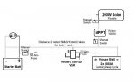
200Watts of solar, MPPT, 200AH of battery, and the ability to charge via alternator when running.

Though Im equipped for a full 200A of charging from th alt if available and if the batteries want it.
Wiring is sized for 200A, fused for 200A and uses a 200A continuous duty relay.

Huge side benefit for this setup is the ability to not only share available cranking amps from house bank to starter, but to also charge the truck batteries via solar! :ylsmoke:


Experience has shown me this...


* I charge my house bank via the alternator whenever we are mobile, even with available solar.
Doesnt seem to bother anything.

*Earth for camper should also be earth for chassis. If not, make sure you have good grounds straps to make it so.
My camper is not steel, so each and every device has a ground conductor that traces back to the fuse panel.

*Up to you. In order to maintain the house bank deep cycles, you need a power source of some sort.
Solar works great for this with a good charge controller. Otherwise, disconnect the solar and place the batteries on a trickle charger/maintainer.

Regardless, make sure you have the ability to isolate components related to the solar panels. Afterall, they done have an OFF switch!

I did this with inline breakers as seen below

using two of them, Im able to isolate the charge controller from the solar and/or the house bank, just in case.

chassis296.jpg
 

SkiFreak

Crazy Person
So questions to all good people with electrical knowledge and experience:
1) is there implication if the batteries are charged from Alt and solar panels at the same time when driving?
2) is earth connection of VSR in the diagram is connected to vehicle chasis?
3) Does solar panel connection needs to be disconnected (and or covered) when not in use?

1) There is a possibility that charging from the alternator might "confuse" the MPPT regulator, causing it to go into float mode prematurely. Other than that it should not be an issue.
2) Looking at this device, it has a very short ground lead with a terminal. If connecting directly to the chassis just make sure that it is a good, clean ground connection. At the end of the day, follow the wiring instructions provided by Redarc.
3) No. If in the sun then your solar system will work to keep your house batteries charged. If under cover then it will not produce much in the way of power. You can also include an isolator between the solar panels and the MPPT. I would also put a fuse/circuit breaker in the solar circuit.
 

gait

Explorer
So questions to all good people with electrical knowledge and experience:
1) is there implication if the batteries are charged from Alt and solar panels at the same time when driving?
No. The volts at the battery will be the higher of solar regulator or alternator.
2) is earth connection of VSR in the diagram is connected to vehicle chasis?
or vehicle battery negative
3) Does solar panel connection needs to be disconnected (and or covered) when not in use?
No.
 

whatcharterboat

Supporting Sponsor, Overland Certified OC0018
So questions to all good people with electrical knowledge and experience:
1) is there implication if the batteries are charged from Alt and solar panels at the same time when driving?
No. The volts at the battery will be the higher of solar regulator or alternator.
2) is earth connection of VSR in the diagram is connected to vehicle chasis?
or vehicle battery negative
3) Does solar panel connection needs to be disconnected (and or covered) when not in use?
No.
Ditto what Gait said.
IMHO
1) No
2) run the earth for the Zener of the VSR to a battery negative point. Personally I wouldn't go to chassis as drawn. Also both batteries must be earthed together with a decent size cable or you can end up with "RF noise" or worse. Definitely don't take a shortcut and earth them to the chassis individually. I know this from experience.
3) No.

Also in my opinion a two way VSR with an optional emergency parallel switch (while maybe not the ultimate) is a better way to manage charge than the one drawn. The two way VSR allows solar charge back to the start battery automatically and the emergency switch gives you handy jumpstart ability. Check the BEP modular packages available for single engine boats.
 
Last edited:

Bris31

Adventurer
Thanks guys (IdaSHO, Owen, Selfy, Julian and John) for very useful feedback. Very good info about dual VSR, grounding and additional isolator switches for different scenarios.
So from all the inputs, new circuit diagram looks like this:
 

Attachments

  • ElectricalDiag2.jpg
    ElectricalDiag2.jpg
    41.1 KB · Views: 606

SkiFreak

Crazy Person
Just a few quick observations about your latest electrical design...

Normally you only need one fuse/circuit breaker in a circuit. So, putting a fuse on either side of the battery isolator is probably overkill. If the battery isolator has a voltage sensing wire it will probably need to be placed close to the start batteries. Again, follow the instructions supplied with the VSR.

Given that you have chosen to go with the Victron 100/30 MPPT regulator there is no need for a manual switch on both sides of the device. This particular regulator is powered from the PV panels, so disconnecting the PV input will power off the MPPT regulator. I would replace the manual switch between the MPPT regulator and battery with a suitable fuse/circuit breaker.
Just a quick note about this particular regulator... The PV side has effective reverse current protection, but the battery side does not. If you connect the battery wires incorrectly you will blow an internal fuse in the unit that is not accessible or repairable!
Take it from someone who knows from first hand experience. :(

If you are planning on doing the electrical wiring yourself, you should do it in a way that gives you the best possible end result. This means not scrimping on the quality of the connectors and wire that you use.
The general rule I use in wiring is to make the cable lengths as short as possible and have as few connections as possible/practical. You should note that every connection is a possible source of high resistance, so using high quality connectors, although normally more expensive, is worth it. Many auto electricians use those couloured Utilux connectors (red, blue and yellow ones). These connectors are not rubbish, but they are not brilliant either. Personally I rarely ever use them myself. I tend to use bare terminals (that I get from electrical wholesalers) and heat shrink. The use of the correct crimping tool (no matter what connectors you use) is mandatory and ensures a good "cold weld" between the connector and wire.

My advice, for what it's worth... save money on other things, not your electrical gear and wiring!
 
Last edited:

IdaSHO

IDACAMPER
Just a few quick observations about your latest electrical design...

Normally you only need one fuse/circuit breaker in a circuit. So, putting a fuse on either side of the battery isolator is probably overkill. If the battery isolator has a voltage sensing wire it will probably need to be placed close to the start batteries. Again, follow the instructions supplied with the VSR.
!

FYI it is common practice to fuse BOTH sides of the relay between the two battery banks.
And it is pretty ill-advised to suggest otherwise.

The fuse is there to prevent meltdown if the wire is compromised in any way.

Fusing one end does very little. You need to fuse both, as you have a battery at both.


For more info regarding "split-charging" check out this page:
http://www.12voltplanet.co.uk/split-charging.html
 

Bris31

Adventurer
Just curious to know on which terminal (positive or negative) people on the forum set up manual disconnect switch (or kill switch)?
 

Alastair D(Aus)

aging but active
comments

At the risk of repeating what others have said.

1. Minimise the number of joins and terminals eg replace the switch and fuse by a circuit breaker that can be manually tripped. This also helps by not having to carry multiple spare high current fuses that can be expensive and a problem if you blow one or more in the wild.
This is an example of a marine type
https://www.whitworths.com.au/main_itemdetail.asp?cat=123&item=84627&intAbsolutePage=1

2. On my truck, Isuzu NPS300, the factory fitted battery isolator switch is very close to the battery and in the Negative line. It is between the battery negative and the chassis connection from where multiple other wires fan out.

3. I have a high current CB (200A) close to my house battery bank in the positive line and all other connections go from there. This ensures that any wire or device that draws a high current will disconnect the battery hopefully before wiring gets fried. I also have a Blue Sea latching relay after the CB that will get switched off under various fault conditions. I have been particularly cautious as I am running 320AH of LiFePO4 batteries that can absorb and deliver huge currents.

4. As said by others keep all wires as short as possible, use extra insulation like split corrugated pvc where there is any risk of damage by movement or sharp edges. Use cables that are well capable of carrying the expected current. Most poor performing systems can be traced to under sized cable and the associated voltage drop.

5. I separate my load circuits as much as possible by using a good quality fused or CB distribution panels. This means that if one circuit fails it does not pull down multiple lines and it is much easier to identify where the problem is. It also allows you to have lower value fuses matched to an individual load device rather than a high value feeding multiple loads. The low value fuse/cb will blow quicker under a fault and do less potential damage.

6. Carry a multimeter in your vehicle. They are cheap now and are a great help if you have a fault.

7. I agree with Skifreak (again?) about using quality connectors. I have fixed several problems in other peoples vehicles by redoing joins often by just soldering it. A common fault is the crimp just not being squashed properly and a high resistance connection results.

Pontification over.
 

SkiFreak

Crazy Person
The battery is part of a circuit, so disconnecting either the positive or negative lead will have the desired effect of breaking that circuit.

If you are simply installing a switch so you can prevent power drain when in storage it really does not matter if you disconnect the positive or negative lead.
Just remember... such an isolation switch, be it on the positive or negative, should never be used if the engine is running. Doing so could cause major issues with your ECU or alternator.
If you want an isolation switch that totally disables the electrical system in the vehicle (like in a race car) then it needs to disconnect the ignition and alternator circuits too.

On my start batteries I have the disconnect on the negative.
For me this is the best solution, as it allows me to easily disconnect all earth connections to do welding on the truck. The negative cable from the battery connects directly to the isolation switch and the other terminal of the isolation switch is then connected to a common negative buss. All negative connections are made from the buss.
 

gait

Explorer
if disconnecting with spanner then negative first. If positive first there is possibility of touching chassis with spanner.

by convention I place all switches in positive wires.

Fuses in solar panel wires can be a source of long discussion. The panels are a current source, its unlikely a fuse size can be found that will both allow the max current from the panels and blow, as the max current will never be exceeded. A kill switch for panels can be useful.

The big fuse that protects all wiring from battery protects wires between regulator and battery.

With voltage sensitive relays (which I don't have) I prefer to be able to manually override both disconnecting and connecting the two sets of batteries. Just covers all possible conditions.
 

Bris31

Adventurer
Thanks all for the good ideas and describing your setup - sometime in different ways but proven.

So just to cap the discussion on cutover switch location - convention is to install on the positive line but equally good if installed on negative.

And to make number of connections less, combine cutover switch and fuse with manual circuit breaker.
 

Attachments

  • ElectricalDiag2.jpg
    ElectricalDiag2.jpg
    41.6 KB · Views: 711

Forum statistics

Threads
186,626
Messages
2,888,232
Members
226,766
Latest member
Josh00333
Top