Designing a complicated power infrastructure, seeking inputs on my inputs and ouputs

Bear in NM

Adventurer
If its any consolation, your pictures might just help me out. I am familiar with that panel in my AV, and I am going to need to plumb in a keyed source for my Garmin GPS. It never occurred to me to try and match up a connector. I certainly know better than to use a splice connector on an existing circuit. Or a splice type connector on anything, for that matter. In my Jeep, I just installed a aux fuse panel under the dash. Looks like I have a date with my multi-meter, and probably a wiring diagram to see if I can find anything in that panel that mates up to a open fuse slot in the fuse panel under the hood.

While I have a brake controller already installed in my Av, I just took a quick look at controller pigtails on line, and they run about 10-15 dollars. Might be cheaper to get a connector that way. Go figure....

Craig
 

rayra

Expedition Leader
Ignore my pictured red wire placement, I'm actually running from the 4th pin from the top left corner of the panel array. That top left cluster of six connector pairs should be marked as the SEO cluster on the wiring diagram stuck on the inside of the cover shield for that panel. Some of the SEO pins are constant hot, some are switched. I just probed with a meter, using a random firewall bolt down there as a ground, to find a switched-hot pin.
The diagram label is a bit disorienting. The orientation of the panel is taller than it is wide. The diagram, if you orient its dimensions to the panel, will be rotated 90deg out.
 

Bear in NM

Adventurer
Thanks. Yes, I have figured out when confirming my brake controller and doing my double din that on-line, book and cover pictures are a little goofy. I'd really like to find one slot with power and ground in a single connector, to avoid creating a grounding "nest" like I have done in the past. I'm trying to keep my Av neat and tidy, unlike my Jeep that was more like a rat's nest of wires. Safe, but messy.

Craig
 

rayra

Expedition Leader
Well I jarred my jury-rigged connector loose again on the long trip back home tonight, so Something Must Be Done. Tomorrow I'm going to improvise some more and fully secure all the slack wire so it doesn't put any leverage on the connector and maybe do something stupid like put a dab of hot melt glue in a plastic-on-plastic spot near the connector to lock it in place for the time it takes my to scavenge a proper factory connector, or find a generic connector that's sized to fit that small pin. Or get the 'add-a-fuse' style splice / tie-in fitting and switch to using a switched fuse in the main power center under the hood.
Was planning a junkyard run soon anyway. And I'm NOT paying $53 for a factory connector. I'll use a manual dash switch on an always-hot line, before I'll pay that much for a single connector.
 

Bear in NM

Adventurer
As I have a week long hunt coming up at the end of the week, I only had a couple of hours to get my Garmin wired up last weekend. I went with the add a fuse, on a 10amp accessory fuse, in the fuse panel that is on the end of my dash, facing the door. I'll do a proper job, when I have more time. The add a fuse gizmo's are certainly better than they used to be, as the one I got replaces the original fuse with a blade, then a fuse on top for the original circuit, with a second fuse for the new line. As my Garmin also has a fuse in-line, I am certainly safe. The ground was an easy tap to one of the big bolts coming through the frame, right at this panel. It only looks like hell when I remove the fuse panel cover. And it's only a 1 or 2 amp device.

I'll do it up proper when I get some time, but felt it was smarter than loose wires under the dash, with muddy boots, in and out.

Craig
 

rayra

Expedition Leader
Well I finally ordered the inverter and a few more electrical connections. I went for the Bestek 1000W. It will do for my near-term needs. Left it sitting in my Amazon queue until they blinked with the 20% discount and hit them up for it. Looks like I've got a 4 in 5 chance of it working properly. That's good enough for the very low price of $70. I'm not willing to pay 4-5x as much for 'sureness'.

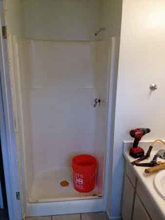
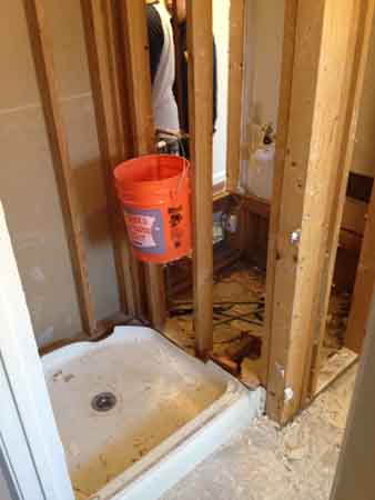
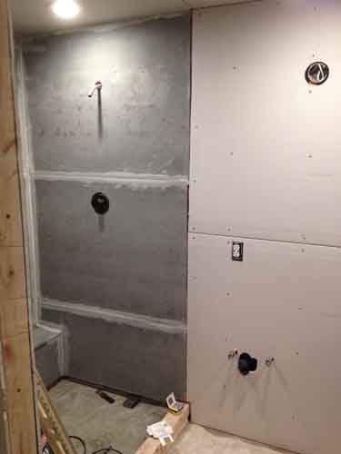
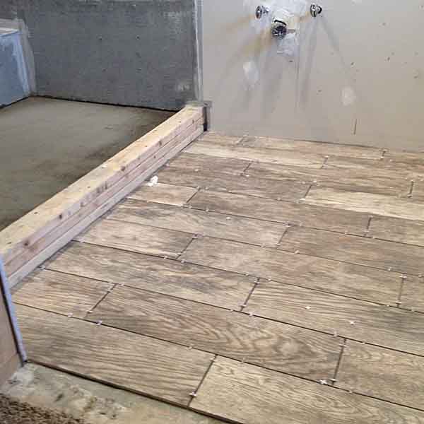
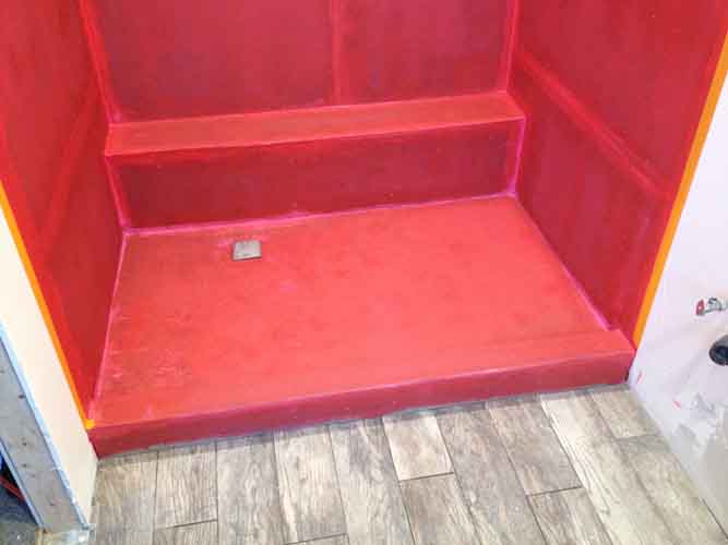
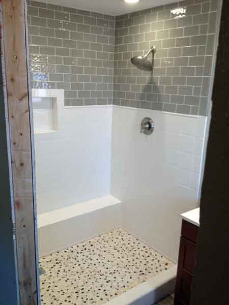
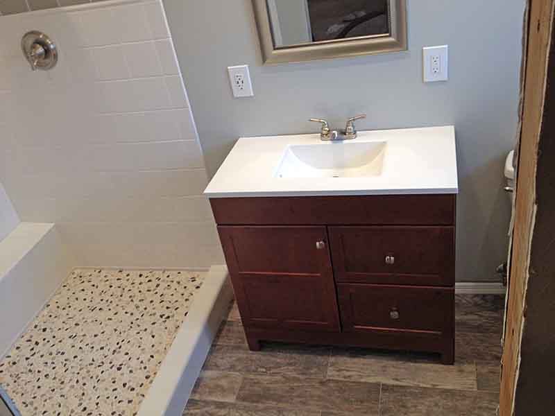
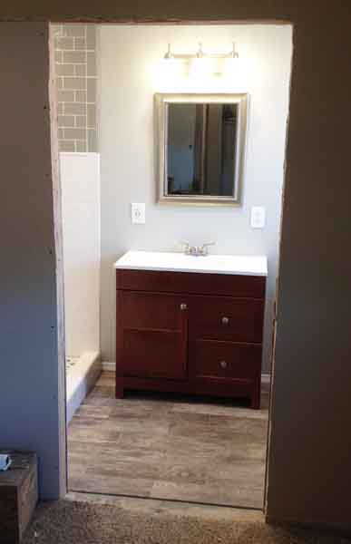
But I still don't expect to do the main cabling to the rear to supply it, until after Thanksgiving. I should be able to run the cables and complete the 4th stage of this install by Christmas. Too much other stuff to do before Thanksgiving. Working as an election precinct inspector. And I've been busy the last several weeks driving hither and yon with the Sub loaded with tools and materials, doing bathroom remodels for various relations. Curse of social media. Help one and the rest start clamoring when they see the results. I've been doing a ton of tile work for someone that isn't a tile man by trade or training. Had a lot of practice at it an all the other trades the last 18-20yrs, though, so folks are happy with my works.

Just finished the bulk of this bathroom a week ago. Still got some wood finishing work to do on the entryway and a sliding barn door to create for it. Turned a 3'x3' fiberglass coffin of a shower into a palatial 5'x4' ceiling high one and brought the rest of the bathroom forward in time forty years.

hugh001.jpg
hugh002.jpg
lompoc043.jpg
lompoc046.jpg
lompoc52.jpg
lompoc61.jpg
lompoc65.jpg
lompoc64.jpg
 
Last edited:

rayra

Expedition Leader
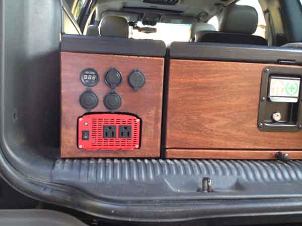
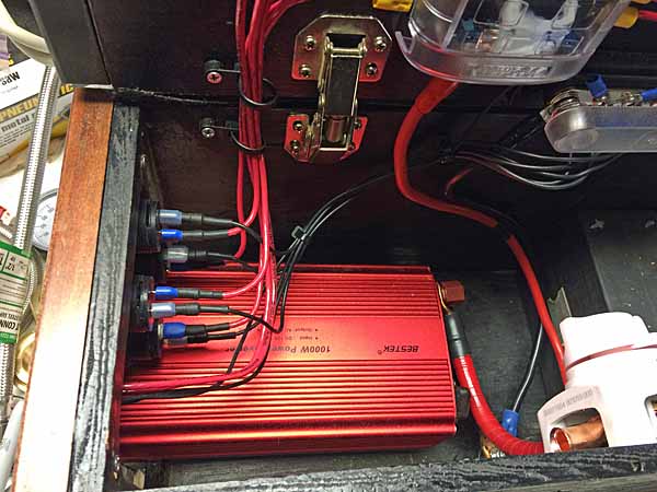
Got the inverter fitted / cut in today. Wound up a little bit off-center as I was trying to cover the previous cutout for the 3rd row power outlet. When I eventually re-fit the faces with a better piece of hardwood, I'll get more refined with the spacing / arrangement of the power stuff.

auxbatt061%20inverter%20fitted.jpg


I'll wrap the end of the inverter with some dense foam tape to fill the gap between the inverter and the wood face plate. I cut it a bit wide on purpose, sort of a half-assed idea that the gap around it would serve as an exhaust gap. But the inverter sucks air in from the face and vents it out the back. And if I use it in a prolonged manner I'm just going to open the lid on the whole box anyway.

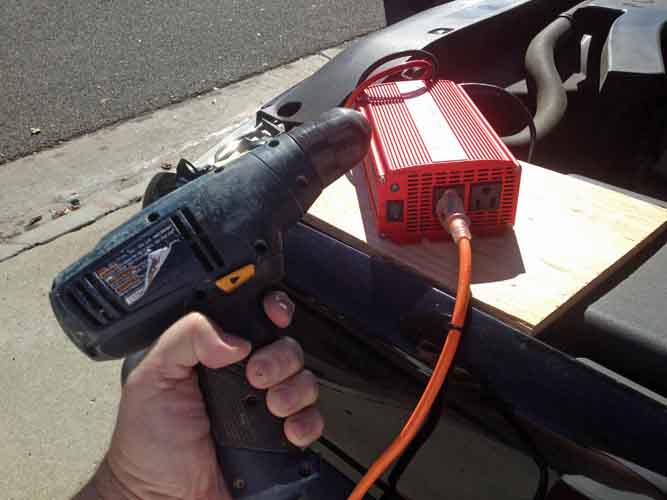
I used the inverter's included battery clamps and did some trials with a bunch of my power tools. Disappointingly the table saw proved too much of a start-up draw, causing the inverter to trip / shut off. I did these tests with the vehicle off, using just the starting battery. Maybe I'll try it again later with the truck running and both batteries joined. But I don't think that will matter.

auxbatt060%20inverter%20tests.jpg


Too, I might try a test for giggles, using a computer UPS as a capacitor / buffer of sorts, plug the saw into the UPS, then the UPS into the inverter. Maybe the UPS can provide the initial spike and the inverter maintain it in operation. And none of that even factors in using the tools under load.
Anyway, it will work for pretty much everything else I want to do on the glamping side.

auxbatt062%20current.jpg


Pretty much all that's left is the major cabling and hookups. And that will entail gutting the back of the vehicle, durign which I'll get a bunch of other things wired up as well. That much work might not happen until after Christmas. Don't think I can get to it before, got too much other stuff to do.


6375
 
Last edited:

youngdogs

New member
Another issue is that the 1/0 run is overkill for the smaller power ports, but is just a bit bigger than a ~1200W inverter would benefit from. And marginal for a 9500 or 12000 class winch at the rear. in reality I might never get around to the ~$1000 expense of the heavier winch kit. I also have reasons / plans that would benefit from a lighter winch at the rear. Which 1/0 would suffice for. So for all my various plans the 1/0 suffices for everything except a 12k winch at the rear. And even then it might work for short duration short distance pulls just fine. So I'm sort of sanguine about the capacity of a 1/0 (or equivalent) power feed. And 200A fusing.


3560
If you're still concerned about wire size negatively affecting the size / pulling power of your future winch purchase, you could always throw a snatch block in one of your drawers for peace of mind.

The theory / benefits of using a snatch block:
http://drivetech4x4.com.au/blog/4wd-action-five-minute-instant-expert-snatch-block-recoveries

What Warn offers:
https://www.warn.com/truck/accessories/snatch_blocks.jsp
https://www.warn.com/truck/accessories/snatch_blocks_HD.jsp

Consider it similar to insurance, it's there if you need it. Just a thought ...
 
Last edited:

rayra

Expedition Leader
Yes, thank you, I am familiar with the power multiplying effects and will make use of them. I also need a good sand anchor and and longer cable, as there's a dearth of trees in my usual haunts.

MagicMtnDan, here's roughly how -


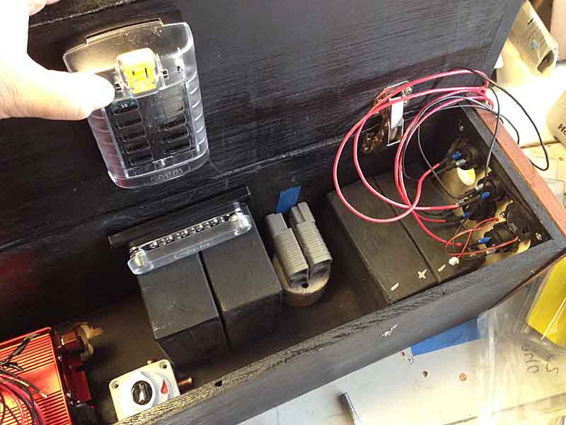
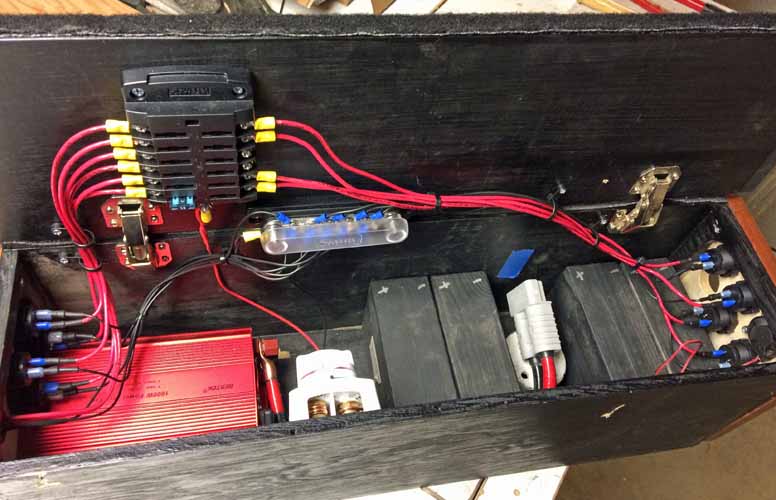
Fiddling around some more with the internal arrangements for my power module. I think I have all the parts I need now. Just not sure yet about the optimum arrangement. And I'm trying to hold options open for a later addition of some small sealed lead acid (SLA) batteries and a solar charge controller, in conjunction with some roof mounted or external (on the ground?) solar panels.
The components are big and blocky, the space is small, but I think I'm figuring it out.

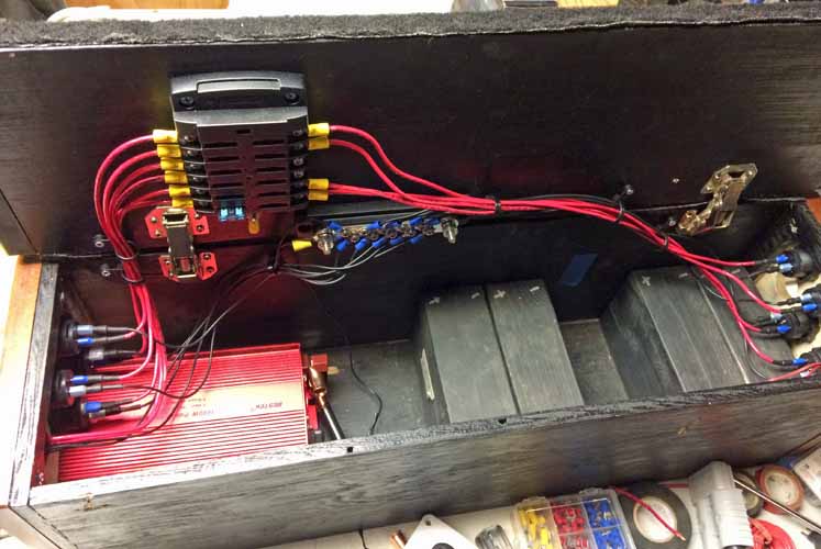
I'm mounting a large fuse block to the inside of the lid of the Module. As well as a separate grounding bus bar. They'll be mounted closer to the Liftgate end of the vehicle for easier inspection and servicing. Each power socket on both ends of the Module will be individually fused. I was originally going to fuse each like socket on each end to a single shared fuse, but it was only a few bucks more to provide a separate fuse for each.
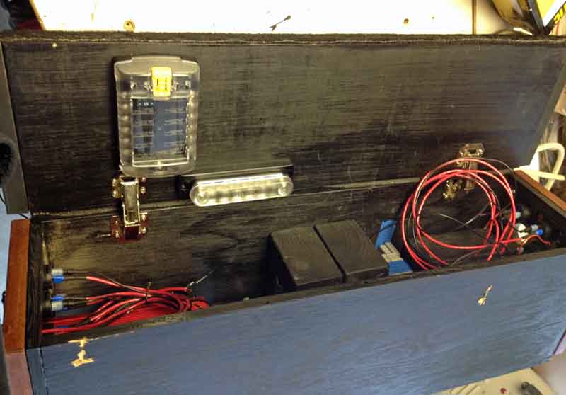
powermodule100.jpg


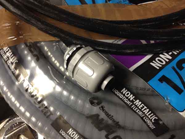
I'm going to be using plastic flex conduit with their compression bulkhead fittings as an armored pathway for the heavy cabling to my aux battery. The 2/0 cabling just fits within. I earlier mentioned I could pass a wire snake clear thru the vehicle's box frame, but decided running two cables thru it might incur the very damage to the cable insulation that I'm trying to guard against. And I further decided just mounting the cable runs along the top inner frame most of the way was insufficient protection as well. My haunts have a lot of sharp gravel and the cables' proximity to wheel wells at both ends causes me to want more protection thus the conduit. The cables just fit thru the compression end fittings, and loosely in the conduit.
100' of flex conduit was $34 at Lowes. The connectors <$2ea IIRC. I expect to use ~70' of it. 26'+ for each main run and 4-5' for each rear hitch run.

powermodule108.jpg
powermodule109.jpg


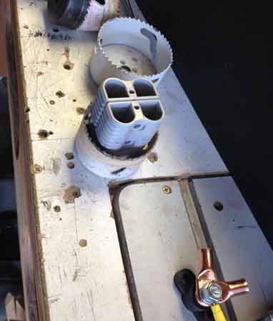
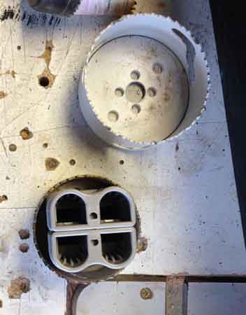
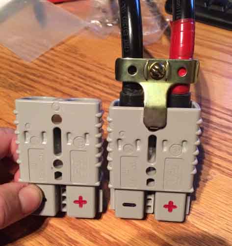
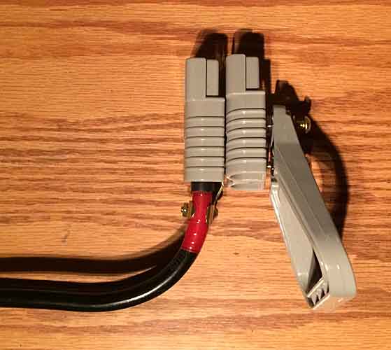
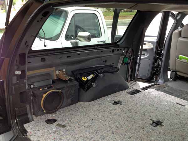
These will be routed to a penetration of the cargo floor trailing the driver rear tire, back behind the interior trim panel. They'll terminate in the large Andersen power connector, pictured earlier. That connector will be mounted with a bracket to the forward end of the subwoofer box, with the connector mouth flush with the cargo area sidewall trim panel. My further plans include another power coupling at the rear bumper for a receiver hitch -mounted winch. In my design that means stacking two connectors at that side panel mount.
I'll be stacking them base to base, so they better fit a round opening.

powermodule106.jpg
powermodule107.jpg


Those connectors will be mated to with a matching pair inside the Power Module. Which will have a matching hole cut in its side. Positioning of the stuff inside the vehicle side compartment dictates placement inside my Module, and that drives placement of other things inside the Module. The wood blocks are simulating the SLA scooter batteries mentioned earlier. They're about 10.5Ah ea, x4 if I can fit them. Nearly the capacity of a third group 34 battery.

powermodule102.jpg


I intend to route the wires from the end panel power connectors thru some anchored loom along the top edge of the Module near the hinges, transitioning to an anchor on the lid edge near the hinges, then branching to their respective fuse and bus bar connections. That will get all that up and out of the way, I'll zip tie and bundle things like a telecom / aviation install.


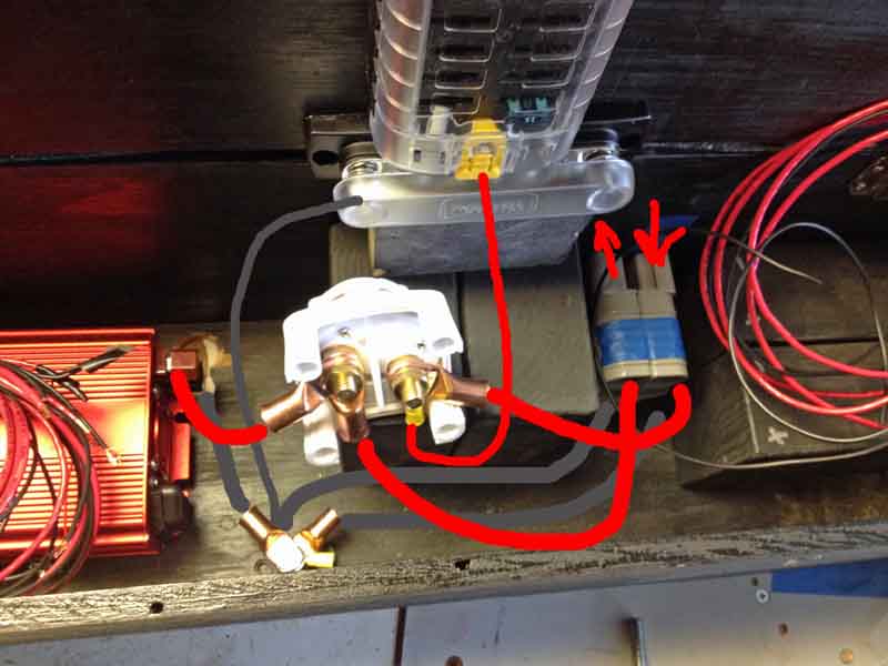
Then there's the issue of the main power distribution and cutoff. The main power line from teh Aux (+) will have a rotary cutoff at the battery terminal. Then pass thru the anderson coupling to the Marine rotary switch (white component in these pics). It will be mounted high on the side wall opposite the hinge side. It's positioned in these pics to show its underside and terminal connections.

The illustrated wire routings are not accurate, just illustrating roughly where things are going.

powermodule103.jpg


Basically the power comes in the box and goes to the marine rotary switch and the feeder line to the fuse panel is always hot (on the same terminal post), as long as the Aux battery connection is on. The marine rotary switch then controls power to both the 1000W inverter and to the future rear bumper connector.

Visible in the bottom of the box is another standalone terminal bolt, for the major ground lines. The studs in the bus bar are the same size, but the routing is problematic for such a confined space and thick stiff cable.

When it's done, I expect to have enough slack and range of motion to be able to plug or unplug the andersen coupling and remove the box if desired.

The space on the right / forward half of the Module lid is for a future likely solar charge controller. I'm considering a bus and feeder line that will charge those smaller batteries from both the vehicle alternator and from solar, with a diode on the vehicle line to prevent drain from these smaller batteries by the vehicle or winching operations. And likewise a diode on the feeder line to the fuse panel, which the small batteries will also power. Thus isolating the added small SLA batteries from major drains. While allowing them to be charged from both solar AND the vehicle. And I have to figure just where to tie in the solar controller so it also tops off my Aux battery. Have to draw out that logic diagram still, haven't thought it all the way through.

My intention remains to be able to power just about anything at all, both inside and outside the vehicle.

I'll also likely in the future get a much larger inverter and fit it with an andersen coupling so I can power heavier tools if necessary.

What I really need to do is the electrical math to figure how much drain at what ratings I can sustain and for how long, with the vehicle off and with it running and with and without solar feed. Doesn't do me much good to power a table saw in the middle of nowhere if I can only do it for 5mins. But I guess that's what a 2kW+ generator is for.


eta I expect to measure my heavy cabling run with standard household wire, then cut my heavy cable to match with a few feet extra. Then I intend to feed the cable into the conduit and then route / wrestle things into place under the vehicle. I'll anchor the rear end with the bulkhead fittings and solder the andersen lugs on the cables and mount the connector. That will 'fix' the orientation of the cabling so I'm not fighting that later. Then I'll get teh cabling runs under the vehicle and up into the narrow gap between front wheel well tub and firewall, rising up to the aux battery location near the existing cabling and charging solenoid. I want the conduit up somewhere between frame rail and bottom of the battery tray. I'll seal the conduit ends to the cables in them, to prevent water intrusion. Then the cables will continue their rise to their terminating connections on the Aux battery. I'll use conduit clamps and self-tapping metal screws to affix the conduit runs to the vehicle frame. I'll probably zip-tie them first as I go, for a rough/ quick attachment, until I'm sure of their locations, then bolt them down.


8000
 
Last edited:

rayra

Expedition Leader
Got a bunch of work on the power module internal arrangements, today. Still sort of in a 'mockup' mode, slouching towards completion. There's a couple small pieces I need to get before I can hook everything up in the vehicle, as well as a load of working tearing up the cargo area to do so.


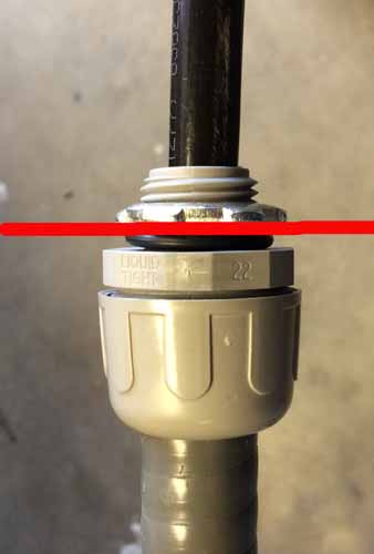
First off is the home electrical conduit I'm going to run under the vehicle, and the bulkhead / compression / waterproof fittings I'll use to pass thru the vehicle floor. The red line will be the sheet metal floor. Pic is a little larger than life size.

powermodule120.jpg


That's the 1/0 cable in the fitting. I'm using flexible conduit. There's a bit of room for the cable in the conduit, it might be possible to pull the cable thru the conduit after it is in place. Have to consult with my electrician neighbor on that idea. I'm fine with loading the cable in the conduit before wrestling / routing it under the vehicle.
Either way, I'm going to have to torch-solder the lug on one end (probably cargo area) with everything in the vehicle. Don't think I want to fit it all, mark the cable and lug orientations, then drag the whole thing back out to do the soldering. But maybe.


Here's the overall setup -

powermodule122.jpg


That's a Blue Sea 12-fuse panel, and a (10) point bus bar, also from Blue Sea. I've described the other stuff previously. The blue tape middle right in the shadows is where the big power connector will pass thru the side of the box. There's a good amount of room for the two pairs of 10.5Ah scooter batteries (for a likely future solar expansion)


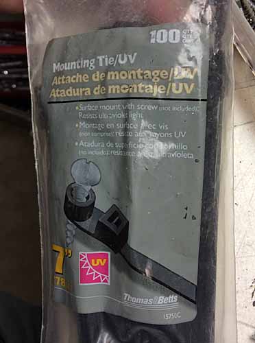
I used a variety of zip tie common in telecom. It's made with an eyelet so you can screw it in place. I've left them somewhat loose for now as I was experimenting with layouts and wire routing. And so there's some movement without chafing, as my wire runs cross from the fixed box to the swinging lid.

powermodule121.jpg


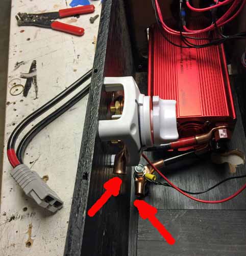
Down in the bottom fo the box I have mounted a single terminal bolt as a common grounding point. The copper lug pointed to the right will go to the big power connector. Ignore the skinny black wire, that was just a fitting and dimensioning mockup. It will probably be a #4 wire connecting that terminal to the ground buss bar.

powermodule123jpg


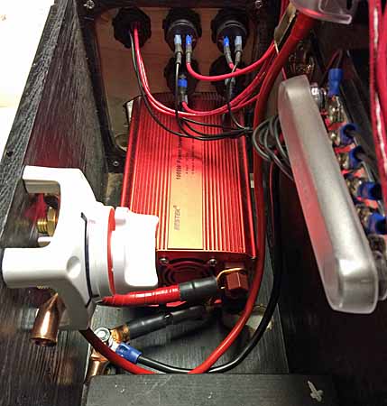
And same for the thin red wire in this pic, going from the white rotary cutoff switch. The plan is to have an in-line rotary cutoff at the Aux Battery under the hood, on the cable to this rear box. Connecting via the SB175 connector to this rotary cutoff in the box. The feeder line to the fuse panel spawns from the same connection post, so all the smaller different power ports on both ends of the Power Module will normally be hot. Turning the white rotary switch then energizes the line to the 1000W inverter. And to the future rear winch hitch mount.

powermodule124.jpg


And another angle on the main power feed lug locations. And outside the box, the roughed up cable connector. I can't cut the cables to size until after I've rigged its mate in the cargo sidewall of the Sub. That mount location drives several of the Power Module arrangements.

powermodule125.jpg


When it's all done, there's still room for those batteries and a solar charge controller bolted on the inner side of the lid.

The under-vehicle work should commence very soon. Mostly waiting on the rain storms to pass.


8800

eta

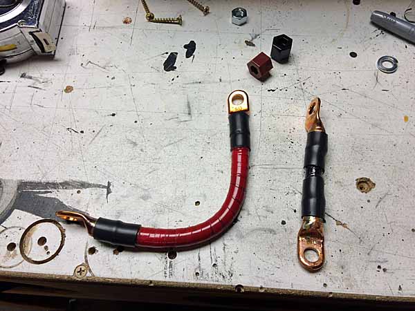
Torch-soldered the copper lugs on the short feeder cables for the 1000W inverter. These cables are probably too thick (1/0 gauge), might cause too much resistance. Maybe dangerous. I dont know yet but I will find out before I put current through them.

powermodule126.jpg


And here they are in place.

powermodule127.jpg


And I fabbed up some 6ga cables for the main feeder to the fuse panel and from the grounding buss bar. These should handle the power needs of a few of those power ports in use at the same time. That too might get interesting, there's no fuse on the line. But I can't imagine a scenario where more than 3 of those power ports might be in use at once, and worst case that's 45 Amps. And each of those ports is individually fused, so any short beyond the ports will snuff it. 6ga is (safely) rated at 55A. So those intermediate feeders should be ok at 6ga. Or maybe I up the positive line to 4ga (70A). Dunno yet.

powermodule128.jpg


I'm using crimp connectors for now, for speed of figuring things out. I'll probably go back and solder those connections later and cover them with shrink tubing.


8903
 
Last edited:

boll_rig

Adventurer
It all looks to be really well done. Essentially you've made a goal zero type yeti but for probably less than half the cost and twice the capabilities; and that fits your exact needs and space. Awesome work and love those little zip ties.
 

rayra

Expedition Leader
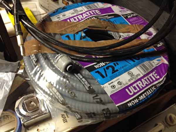
The gray spaghetti is the PVC flex conduit I'll be using to encase the main power cables to the rear. Was a very tightly wound bundle from the factory, trying to straighten it out somewhat before the install next week. Bad timing on my part, too, solidly in SoCal 'winter', some summer heat would be useful on this stuff.

powermodule129.jpg


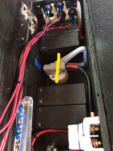
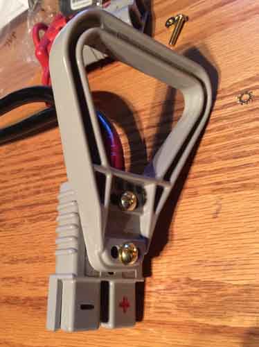
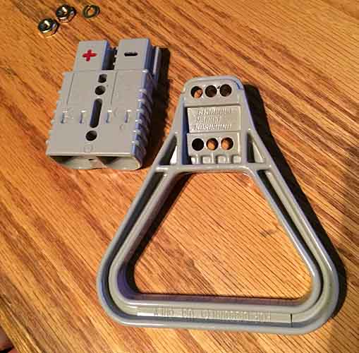
Got a matching pull handle for the Anderson connector. Figured it would be better than yanking on the cables to unplug things. But I also realized late that this connector will be deep thru the pass-thru hole in the side of the box and spanning a gap between Power Module and interior cargo area trim and then thru it to the mounted mating connector. So the plug and handle are going to be up to about this yellow line out the side of the Power Module. Gonna have to re-bend those cables after the truck wiring and connector mount are done.

powermodule130.jpg
powermodule131.jpg
powermodule132.jpg


The handle might not work out at all, depending on how the mated connector alignment works out. Might not have room against the (optional) small batteries. Especially when I stack another connector (for the rear winch plug) in the mix. shrug

Another option is to just put a paracord loop thru the thru-holes the handle bolts into, instead of the handle.


The handle piece also has three sets of holes, so you can offset the handle about 5/16" to either side of the connector, which could be useful in the confines of this box.

powermodule133.jpg
powermodule134.jpg


I also got another Anderson-specific device to try, it's a metal bracket / clamp / strain relief that couples the cables and connector together. That might be totally sufficient. The coupling will be high enough up the bottom of the box that I can fully wrap my hand around the base of the connector and the cables to unplug things. And that alleviates any clearance issues with the big handle. We will see, after I get the cargo area pulled apart and fabricate the power connector mounting in the cargo area sidewall

powermodule135.jpg


eta

The second coupling would come into play when I add an extension circuit for the rear hitch-mount winch. It would be powered thru the box, with the power cut off by the white rotary switch. So the external plug would only be powered when in use.
Stacking the Anderson couplers is easy, using their bolt holes. Two stacked plus a handle, I don't think that will work in the box with a solar / battery setup too. Not without making the box longer and violating the 3rd row seat mounting space.

powermodule136.jpg


9030
 
Last edited:

rayra

Expedition Leader
I've made a couple ~3' mockups of my conduit and cable solution, and have done some initial experimentation on the routing of the cabling, confirming how tight a bend radius I can make in a couple critical locations. And verifying I can cram a pair of such cables up between the plastic front right wheel tub / liner and the firewall at that frame support horn location. It's a tight pass amongst the AC plumbing, battery tray, Aux battery cabling, and all with the exhaust manifold a hand span away. The unshielded Aux battery ground cable to top of frame mounting position is closer and seemingly unaffected by the heat proximity, so these PVC conduits should be a non-issue.

But I am prepared to NOT route the conduits up there. I've got a bit of trouble in doing this, besides the tight quarters. I'm using torch-soldered terminal lugs on these cables. The terminal lugs DON'T fit inside the cables. The stiff cables will not readily slide inside the conduit, especially after three tight radius turns. Four really. I have to basically pre-stuff the cables into the conduit, with the Aux battery terminals installed before rigging them on the vehicle. Then tuck and mount the conduits basically from the passenger rear wheel, threading them forward atop the frame rail and up towards the Aux. I want to have the conduit end in the engine compartment near to where they enter, with the cables extending on to the battery posts. I need to seal the conduit open ends to the cable AND have the terminal lugs oriented correctly. I will likely have to tape up the rear ends of the cable and physically connect the cables to the battery so that their rotation / orientation is fixed as I arrange the rest of the cabling. Yes, that's correct, routing a live battery cable. Whee.

What I really need to do is a preliminary routing just using some stiff house wiring, to get a proper length estimate. Up until now I'm using a very padded guesstimate of a cable run of 25-26'. With the conduit runs about 3' less. As they hang now they are least 25'. So what I really need to do is dry-fit the empty conduit first, get it cut to within a few inches of proper size. And then let those drive the rough cable sizings. I can tape up the ends of one piece and shove it in as I intend to do the install. And I can also proof the method on that too. My plan it to put the passenger side in the air on jackstands and take the wheels off to make it easier to work on things. I can also suss out my conduit clamp mounting locations and even DO those during the test fit. One less thing to have to do on the actual day of the install. And clamping down the conduit will help simulate the rigidity of the actual install. And I'll get to play with my new impact driver. I'll be pre-drilling starter holes and using self-tapping screws to attach the clamps to the frame.

There's not a lot of flex or twist in this residential / commercial cable I'm using. I'm using it because it costs half as much (or less) as comparable 'welding cable'. So far the hassles have been few. There's a couple spots I really need the flexibility, and that will be the main plug inside my power box. I think this rigid cable will make that connector difficult to handle. And I've already spent mor eeffort talking about the hassle of this cable than it will actually be on the day.
When it's actually time to install, drill holes in the floor for conduit couplings and the like, I'll have to form / curve the cable to my intended cargo area mounting location and I'll have to torch-solder the Anderson plug terminals to the cables working INSIDE the cargo area of the Sub. Right now I'm intending to make a plywood work platform, with my small vise mounted in it. That will hold the lugs upright just as it has in the past, while I torch-melt the solder in their cupped ends and heat the exposed wire and plunge it in. And I'll make a propane torch holder on that platform too, so I can socket the torch into it while I'm working.
And with all the doors / windows open and a box fan sitting in the middle row seats blowing out the back, I should have no trouble with fumes or residual stink. All in all, it will take longer to set up than actually execute.

I also still need to fabricate a rigid mounting bracket for the Anderson connector. A sort of bent hoop affair, with some standoff from the mounting surface so I can thru-bolt the connector to it and modify things later if / when I add the rear hitch extension power connector (double-stacking the connectors as pictured earlier). And the mounting surface. I'm intending to use the forward facing flat surface of the box the factory subwoofer is mounted in. Right this minute I'm not even sure what that is made out of. I'm hoping it's rigid plastic and not some sort of fiberboard crapola. I anticipate possibly sandwiching that end panel between two layers of 1/2 plywood to reinforce it and provide a sufficient mounting location for my plug.
There's a few examples of mounting brackets online, but they all seem made by hobbyists, which pretty much means I can make one just as good. I could bend one of these from some aluminum plate, readily enough. I already have that small press break to do it with, too.

_57.jpeg


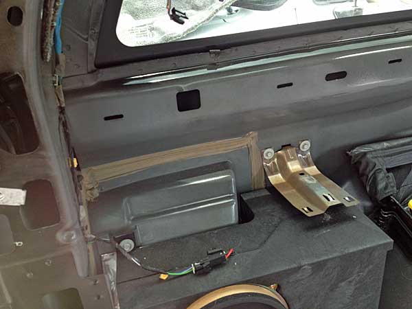
well ****, that floor penetration space is a LOT tighter than I recalled. See that narrow area where the rectangular box abuts the curved wheel tub? I thought that was at least 4-5" wide. it's effectively zero at the outer skin.

mess05.jpg


From the bottom it's a wide expanse. I didn't realize much of that space laid under the subwoofer box. I think I'm going to have to cut down the subwoofer box to gain the room. And that simplifies my connector mounting location somewhat. I'll dismount and dismantle the subwoofer box, cut 4-5" off the forward end, size a piece of 3/4" plywood to snugly fit in its open end then epoxy and screw it in place. Then I can attach my connector to that.

The box itself looks like that resin-plastic-fiberglass ****. Sturdy enough. If I get fancy enough with my surgery I can even slice the end off the box like a loaf of bread and re-attach it. Even have the plywood jut out a bit to mount the end cap over. Cut the end off with about 1/4" lip to form a cap. Getting fancy now.

butyl01.jpg


eta here's a pic looking up at the underside of that space, marked up. The yellow circles will be where I drill thru the floor with a large step drill, where the bulkhead / compression fittings for the conduits will mount and the cables pass thru. the two cables from the Aux battery, to begin with. With an optional two locations when a rear bumper power coupling is added.

meh picture later, photobucket is bogged down right now, probably with late night server backup.


9307
 
Last edited:

Forum statistics

Threads
188,395
Messages
2,904,126
Members
230,274
Latest member
mbauerus1
Top