Designing a complicated power infrastructure, seeking inputs on my inputs and ouputs

DiploStrat

Expedition Leader
...
The Blue Sea stuff is nice, but what a price premium. $17ea for fuses?

Depends on what your truck is worth, how much time you have to fabricate cables and mounts, and how much space you have for them. :)

Congrats on the 14v reading.
 

Bear in NM

Adventurer
Looks like it is coming along nicely. Interesting trying to tie in the RAP function. But, I think on my 2002 Avalanche, my RAP times out after about 15 minutes or so. Obviously opening the door kills power instantly, but in testing my dome and the lights in my bed and saddle bags, the time frame seemed to be about 15 minutes. I think those lights may be on a different circuit than my stereo, but I might need to do some additional testing to completely understand the functionality. I had initially tested the lights in my bed, as my truck bed tent has clear plastic over the bed lights, and wanted to know whether they would time out, if left on.

Craig
 

rayra

Expedition Leader
I think it's 10mins for the interior stuff in a Sub.

I'm idly thinking about re-routing the stereo / DVD power to the Aux system for camping use. But right now I'm really enjoying the bluetooth audio / auto connect features. I can listen to streaming audio or podcasts on my iPhone, go get in the car and fire it up and have the stereo come on and auto-connect and start pumping the audio thru the car. I'd lose the totally passive convenience of that if I switched it to the Aux.
And typing that out now makes me think I need a SPDT dash switch to select which battery I want the entertainment system powered from, based on whether I'm it in a campsite / static setup. And that mode change would be easy to mess up / forget to execute. Go somewhere, forget to switch to Aux, play some movies and kill the Main battery. Have to think on that a bit.

I'm filling up my Amazon shopping cart with some Power Module gadgets and some marine battery cutoff rotary switches, and browsing various fuse panels. I'm waffling between using something like a 6-fuse panel and wiring both the front and rear panel like power ports to the same fuse, one for USB ports, one for cig lighter ports etc, OR going with something like a double row fuse panel and wiring the front stuff down one side and the rear stuff down the other.

But I also have some center console radio projects that have been in 'mockup' for well over a year. I might decide to go hot on the radios console first, since I have the Aux battery setup in place
Here's the topic from ~17mos ago, where I was laying the RG-58 cabling to rear bumper mounts, and building the center console for the radios. That all still sits as I left that topic so long ago -
http://www.expeditionportal.com/for...ling-and-heavy-gage-power-lines-under-vehicle


/slow like a glacier, but I get there eventually
 

Bear in NM

Adventurer
Not having a family and kids while camping, I really have no need to move a/v stuff to my aux side. I have a jawbone for music, and if I really needed to play a movie, I would just use my laptop. I then can charge these from my portable solar. With my aux battery install, I had a moment of reflection. Just because I can, does not mean I need to. Heck, my plan was to have the BIG juice at the rear, for a portable winch. Upon reflection, in 25 years of off-roading in the back country of WA, CO and NM, I needed a winch maybe two times, not counting dead elk recovery. I moved the winch lower, on my list.

But, it would be kinda nice to have a master switch that completely moved all non-essential electrical to the aux side. Wondering whether you would have to tap in upstream of all of the on-board vehicle computer connections?

Craig
 

rayra

Expedition Leader
well Bear in my explorations I've found several fuse panels, each with clusters of connections and 4? computers. At this point you almost have to wire the new stuff to a new fuse panel dependent on the Aux battery. It would be major exploratory surgery to excise nonessential circuits to an aux battery.

I'm looking at either a terminal-post-attached small fuse panel much like Jelorian used (A Blue Sea part), or a variety of terminal post connector which accepts both 1/0 cable and a couple 4ga wires. The latter wires would then run to my radios console to feed a small fuse panel there or to the rear.
More to come on that, I need to nail down my architecture so I can order more parts. As it is now I've done just enough planning to build my 'main bus' of sufficient sie to handle all my future plans, even though it is overkill until the later stages.

And as of now I've been laid low with the coughing head cold thing that's going around. So maybe I'll finally get the diagramming done while I lay about the place. Took all I had today to service the rear differential on the missus' Tahoe today. Sinus headcold, ear canal inflammation giving me positional vertigo and nausea. Damned nightmare, wound up puking in the shrubbery.

I've got a bunch of stuff inbound right now. CB radio, 4' Firestik, external speaker, to complete my CB plans. A variety of 1.25" panel mount power ports, cig lighter and USB types and a matching round-faced voltmeters. And some Anderson SB175 power connectors and fittings for 1/0 cable and some smaller 15A 'standard' Anderson pairs in a panel mount.
Most of that will wind up in the rear Power Module setup.

But the joke's on me, as I have yet to decide what my fusing and fuse panel arrangements are going to be. So I can't do more than install that stuff when it comes.

more soon


eta oh and I think this will be handy.
https://www.amazon.com/ANDERSON-POW...id=1473640267&sr=8-15&keywords=anderson+sb175

Found it while shopping for deals on Anderson Power Pole connections. It's a handle that bolts right onto the large SB175, you pull on the handle instead of your cabling. Or your connector in a tight space.

Here's a rough diagram of what I intend in the cargo area, the power connection for the rear Power Module.

auxbatt022.jpg


I'll run the 1/0 cable from the Aux (+) along inside or above the frame, back and across, aiming for the small flat floor area right behind the left rear wheel tub. Between it and the fuel filler tunnel and the subwoofer box. I'll penetrate the floor (bulkhead grommet and silicone) and terminate in an Anderson Powerpole SB175 connector, whose mouth will be near flush with the cargo area side panel. I'll cut a suitable-sized hole there for it. This will align with the side of my 'Power Module' box, which will have a mating connection within it. This will make the Power Module itself removable when the full cargo area is needed. The module will have a matching hole thru its side. The SB175 connectors are plugged together thru the holes. The handle I mentioned above would make this connection easier to manipulate.
The body end of the connection will be bracketed / fixed to the vertical end of the subwoofer box (if that box is sturdy enough).


Here's a top-down view, with a very approximate and partial layout.

auxbatt023.jpg


I'll use the marine rotary cutoff switch as the cutoff for the rear bumper winch connection. But the hot side will also be my terminal connection point for the heavy draw of the 1500W inverter and the connection for the 4AWG / 80A feeder that will supply the local fuse panel in the Module that will power all the other power connections in the Module, both front and rear faces.

The plan is add the bumper connections as the last phase of the project. Then there will be a double-stack SB175 setup. They're designed to bolt to each other. Maybe until that phase I'll use the rotary cutoff in the Module as a master switch for everything in the Module.
It's all going to be much tighter than the weak diagram above implies. Especially if / when I add the additional batteries, solar facility, and the 1500W inverter will take about 1/4 of the floorspace of the module. It might not all fit without some vertical stacking.


2300
 
Last edited:

rayra

Expedition Leader
Any reason not to use a chassis ground at the rear corner, rather than running a phat 1/0 line all the way back to / from my Aux?

I seem to have a good factory-equivalent ground / negative location established now on the passenger front frame rail, right behind the front shock tower. I've got some more 5/16" rivnuts inbound (still can't find the ones I'd ordered some time ago) and will re-do that connection later. But for now the self-tapping 5/16" bolt seems to work just fine.

So I'm thinking to repeat that method at the rear corner, near the left rear shock top mount. I've found some rear winch wiring articles that discuss doing that. But the more I read about resistance issues and return paths, the more I think I should just run the 2nd 1/0 to the Aux (-) post.

Further compounding my fuzzy logic, I've already chosen and implemented a fat 1/0 ground cable on the Aux battery. From my limited reading this ought to support whatever loads I plan to place on that electrical setup. So the question seems to be one of 'getting away with it'. But that doesn't seem right either. Not when I'd be running cable anyway and a second cable is all of $30 and very little extra effort.

Any insights or reference material on this?
 
Last edited:

rayra

Expedition Leader
Parts trickling in for the next stages of electrical work.

Got the panel mount for the standard Anderson Powerpole connectors. The connectors are modular and genderless. They also lock together and stack, sort of like LEGO pieces. They're becoming a sort of standard in a lot of hobbies, including HAM radio. So I wanted to have some facility to provide power this way, alongside the other 'flavors'.

auxbatt024.jpg


The larger (but similar) APP connectors for phat wiring. They come in a few different sizes as do their specialty lugs for different wire gauges.
Here's a couple pics of how they'll sit inside the 'Power Module'. The pass-thru hole in the Module and the cargo area trim will be about there. The cabling and terminal connections in the box will have to be placed in a manner and have enough slack / movement that the APP connector(s) can be pulled loose into the center of the box. Not a lot of room to work with.

auxbatt025.jpg
auxbatt026.jpg


The connectors themselves are large and robust and are designed to be bolted together or to a mounting bracket. They'll stack flush with each other, but if you want to use the silicone rubber 'dust boot' with them, you'll have to put a spacer between the connectors.

auxbatt027.jpg
auxbatt028.jpg


auxbatt029.jpg


I'll have to make my choice / purchase of the 1500W inverter soon. It and the size of the marine rotary switch and the location of the mounted plugs in the vehicle sidewall are going to determine the overall layout of the Module contents. Everything else will fit around it.


In the meantime, the 'panel mount' power ports I'm getting are only about 3/4" deep. I'm going to have to relief-carve the back side pf my wood face panels, down to about a 1/2" or so. I can do that on my router table. And I have to figure out the final set of ports so I can set their arrangement and start drilling some holes for mounting the ports. Maybe a grid pattern, maybe a honeycomb pattern. Again I have to determine what inverter I'm mounting.
 
Last edited:

4x4junkie

Explorer
Any reason not to use a chassis ground at the rear corner, rather than running a phat 1/0 line all the way back to / from my Aux?

I seem to have a good factory-equivalent ground / negative location established now on the passenger front frame rail, right behind the front shock tower. I've got some more 5/16" rivnuts inbound (still can't find the ones I'd ordered some time ago) and will re-do that connection later. But for now the self-tapping 5/16" bolt seems to work just fine.

So I'm thinking to repeat that method at the rear corner, near the left rear shock top mount. I've found some rear winch wiring articles that discuss doing that. But the more I read about resistance issues and return paths, the more I think I should just run the 2nd 1/0 to the Aux (-) post.

Further compounding my fuzzy logic, I've already chosen and implemented a fat 1/0 ground cable on the Aux battery. From my limited reading this ought to support whatever loads I plan to place on that electrical setup. So the question seems to be one of 'getting away with it'. But that doesn't seem right either. Not when I'd be running cable anyway and a second cable is all of $30 and very little extra effort.

Any insights or reference material on this?

As long as your ground connection under the hood is good & solid (1/0 AWG straight from battery negative to frame), there shouldn't be any issue using the frame as your return path.
Steel certainly is a poorer conductor than copper, however the sheer size of the frame's cross section compared to a 1/0 copper wire way more than makes up for it.

The one critical item will be how you attach the cable to the frame, both under the hood, and again at the rear: You'll want to use a 10-12 sq-inch copper plate (about 12 gauge or so thick) and three or four bolts to spread out the current going into the frame (wire connections to each individual bolt could work also). This is because the poorer conductivity of the steel can otherwise cause excessive heating of a single-point connection with a high-current load such as your inverter or especially a winch. Use of self-tapping bolts I think may be asking for problems also.

On my own rig I've relocated the underhood battery to under the rear seat. Positive is a 2/0 copper cable, the return is through the frame using copper plates as above, and machine bolts & nuts & dielectric grease on everything. No problems, even with my winch, all the connections remain cool to the touch.


I would've suggested a 5' or taller CB antenna (such as the Francis CB-26 Hot Rod). Performance drops off pretty dramatically with antennas less than 5' tall (matching the SWR can be trickier too).
 

rayra

Expedition Leader
well I think I'd rather lay a second 1/0 right to the Aux (-) than deal with all that plate business trying to use the frame. I may however use a separate frame ground for the smaller electronics in the box in the interim. Dunno. If I stay consistent with the approach used on the Aux setup, I'll just be running the dual 1/0 cables for that main bus anyway, so if I lay that down the rest is moot anyway.
Next couple weekends I'm out of town in opposite directions doing some tiling work. So won't be any major progress until the end of the month. At which time I'll probably run the dual 1/0.

I'm trying to massage everything so the parts arrive, the free time arrives, the money arrives and I can just pull everything out and do the cable and cargo side panel modifications all at once. End up with the hole in the cargo sidewall and the mounted SB175 connector mounted there, hot. Then the box can be modified to match and its internal layout can get underway.


eta yes I know the antenna mount is suboptimum. Deliberately so. Expected general use is convoy ops and I've got overhead clearance issues. When I eventually go far afield with the rig, I'll have roof mounted taller antenna. The bumper mount shorts are just for running around. One of my other planned mods is a ceiling mounted fishing rod / antenna rack. The 18' RG-58 I routed from the center radios console to the back bumper corners and the radios placement will let me access and change antenna hookups without much trouble.
 

dwh

Tail-End Charlie
Let me be the first to blabber on about THHN conductor is not optimal for this application.
This is 'Expo afterall...

Been waiting for someone else to say it. Didn't wanna be accused of mocking. And anyway, too late now, he already bought it.
 

rayra

Expedition Leader
'Let me be the first' to point out how you two 'expert' kibbitzers have opined without adding any value - as in why and what would be better, for my edification or that of the audience.
I expect the answer is 'welding cable / more strands / better coating'. I bought what was workable and available at the time. And am overbuilding for my expected uses, anyway. And I haven't got the budget for perfect / best.

I'll also point out how even more lame it is to withhold information, whatever your reasons / rationale. At least when I'm busy being an ******* to somebody, I'll still pass them information they should have.

You two are starting to remind me of those nasty old coot Muppets, sitting in their theater box, ****-talking everything.

It's a damn shame you two couldn't be more forthcoming with knowledge or advice, or at least as free with it as with your detractions.


Let me expound, since you experts are only contributing koans on the sublime beauty of simplicity and 'wrong wire' -

My local sources only have 'welding cable' in 2AWG. And as I read more on it and WARN's pre-fab rear bumper winch wiring kits - which are also 2AWG, btw - I found that 2AWG was going to be inadequate in my estimation. Recall that I'm wiring up a Suburban, which will be about 7500# in travel mode. A 9000/9500 -class winch is a recommended minimum. A 12k winch would be preferred. And 2AWG on a rear mount has a crappy duty cycle even with a 9500. And basically a 'no go' for 12k. And my electrical and storage plan won't accommodate a rear-mounted full-sized battery. So up I went to 1/0. And there went using available 'welding cable'.

This 1/0 cable is rated 600V / 170 Amps/Ampacity. That's over 100,000 watts. As I understand it, and as my neighbor electrician explained it to me, it should handle any abuse I care to throw at it, in terms of a rear-mounted 12k winch. AND I'm actually fusing it (200A) on the low end of its usability range.

I'll be mounting the cable to the frame, tucking it outboard, inboard and on top, as best suits each stretch. I'm using insulated cable clamps to hold it down and split loom and even heater hose to shield it where it seems necessary. I'm thus unconcerned about its nylon cladding (which itself is rated near 200F), I'd be taking the same protective measures regardless, as my usual terrain is dry desert and sharp rocks.

So if you two have anything constructive or 'value-added', I'd love to hear it. It is after all why I started this topic. And like my other constructive projects here, I'd intended it to be informative for others. And not just for your sport. So I invite you to contribute constructive info, if you can or will.


--

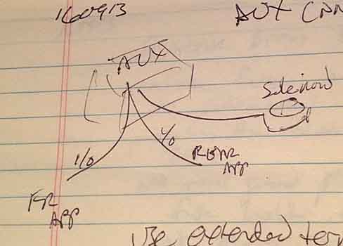
For anybody else with any interest in sharing info and answering questions - would it be feasible to use a single fuse block terminal as my point of contact on my Aux battery, and have THREE 1/0 cables connected to it (power IN / SHARING on the recharge circuit; power to the front winch plug; power to the rear winch plug)? Is there a practical difference in the safety function of the fuse if there are THREE lines connected to it?
The only downside / unknown situation I can foresee is damage to either fore or aft cable while the vehicle is running, in which case the short would draw down those wires and back up the connected feeder line from the isolator and on towards my Starter battery. But that ends in a fuse at the Starter (+) post too. So one or both fuses should blow and that's that, in terms of an incipient electrical fire. And still leave my factory wiring and starter battery unmolested.

https://www.amazon.com/Blue-Sea-Sys...0_2?ie=UTF8&psc=1&refRID=NCFSMQNRRQ4MVV9ASRWN

auxbatt020.jpg


I'm also thinking about hanging a Blue Sea terminal fuse box off that same Aux (+), to run a couple fat branch circuits to feed my radio stack and my aux lighting. But haven't decided on that yet. I'd wanted a rooftop LED bar, but waffling on that, Bro factor is too high. And there will be some additional lighting up front. But I have to make some decisions on alterations to my transmission cooling setup, before anything happens there. The factory external cooler is front and center right below and partially behind the Bowtie. Terrible location. Need to do something about that, before I go cluttering up that area with aux lighting.

auxbatt021.jpg
 
Last edited:

dwh

Tail-End Charlie
Screw you, you offensive ****.

You ASK for input, then when two actual no **** electricians TRY to do that, you immediately jump down our throats.

Which is why neither one of us said anything when you bought the wrong wire. And like I said, it was too late anyway, since you didn't say a damned thing about it until you started posting pics of *soldered* connectors and whining about how stiff the (wrong) wire is.

And this topic has been covered any number of times already. Why should we waste our time saying it all over again just because you A) don't know what you are doing and B) didn't do your homework.

We might have...if you had actually been at all receptive to the "inputs" that you ASKED FOR.

But I, for one, am not going to fight to get you to listen. Nor will I pussyfoot around hoping that your ************** doesn't jump down my throat. I'm done with trying to be nice to you dickhead.


I hope your goofy, overly complicated wank-fest of a project works the way you intend it to. But I won't know because I won't be looking at this thread again.

Because I don't actually care what you do wrong.

I just hope no one else follows your halfassed methods.
 

rayra

Expedition Leader
Don't even feel like reading it right now, Waldorf. Busy building stuff.


auxbatt023.jpg


Did some batch work, prepping wire leads for the power ports / adapters. Still not sure exactly where the small fuse panel is going inside the power module, so I'm wasting a bit of wire making them 'long enough', but I wanted to get on with fabrication. This wood panel is actually the one that will face forward in the vehicle, I went ahead and drilled 6 holes in it. One of those will likely become a small exhaust fan port, or a solar panel plug-in. Haven't decided. But I figured I'd make my construction mistakes on that piece of wood first, instead of the rear-facing panel that is grain-matched to the drawer fronts.
I've got a couple more USB and 12v ports coming still. And will likely order another Anderson PowerPole fixture as well. My goal is to have just about any flavor of power available within reach of any seat, or at the rear. Thinking road trip / camping use, disaster prep, CERT, maybe even Search & Rescue. Being able to support just about anybody with any electrical / electronic gear.

auxbatt024.jpg
auxbatt025.jpg
auxbatt026.jpg
auxbatt027.jpg
auxbatt028.jpg


The spacing is a bit snug. I'm constrained by the interior framing and other things. But this layout is so close the weather covers interfere with each other.
Also, the weather covers are not symmetrical / centric. They'll fit if they're flipped 180deg - I'd like them to open down out of the way of the plug, rather than hover over top - but the rubber tabs that stick into the plugs are off center and the weather caps are then off-centered if they aren't placed upright. Trivial thing and I'm not aspy / OCD. Also considering placing the ports with about a 30deg list to the left, that would then make the weather covers easily accessible. And it doesn't really matter what the orientation of the plugs themselves actually are.

when it's all built, all the wires inside will be routed and ziptied / anchored, like a nice telecom / network install.

Just really can't nail it all down until I choose and purchase the 1500W inverter and the other major components.


Then I went ahead and got some more fiddling done this afternoon. Went for the rear panel, went with a generic layout that ought to work with any of the 4-5 inverters I'm shopping. Not the most stylish layout, but it will work.

auxbatt029.jpg
auxbatt030.jpg
 
Last edited:

Forum statistics

Threads
186,822
Messages
2,889,576
Members
227,160
Latest member
roamingraven
Top