No, they are not, but their relative un-safeness is small enough to not be worth talking about here. I've always been talking about adapters unless I specifically mentioned a shim style of spacer. I was using the terminology for them commonly used on 4WD oriented forums. Coming to off road from road racing I'm well aware of the difference, but using the correct terminology is more confusing than helpful.
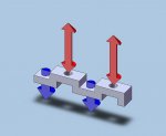
I drew the red arrows uniformly for speed of assembling the picture, but I did not intend to imply that the tensile and compressive forces are equal. They may and may not be depending on the exact application. I did linearize and greatly simplify the model for expediency. Roughly what I modeled is the sequence of linear cross sections from one stud hole to the next, which were then laid out to be collinear rather than curvilinear.
Consider the loadings in a corner. The cornering force vectors generated by the tires point in the same direction, towards the center of the turn. Their magnitudes differ by a small amount due to weight transfer, tire slip angle etc., etc., etc. This cornering force has a lever length of the tire's true rolling radius, which imposes a Moment on, eventually, the spindle. To get there that same Moment is applied to all of the parts in between the tire and the spindle. I am expecting that the lowest elevation wheel stud will be seeing a that side's max compressive force on the outer tire and the max tensile force on the inner tire. The upper-most wheel stud will be seeing the max tensile force on the outer tire and the max compressive force on the inner tire. Since we are dealing with a rolling wheel & tire assembly the wheel studs are rolling through those regions of max tensile and compressive forces while those regions are fixed in those locations. That is where I see the reversing stresses arising.
")
")
