DIY Lithium Packs, Proposal and Discussion

Madoxen

Active member
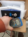
Hi luthj just recieved my batteries after about 40 + days on the boat. Pretty sure u ordered yours from same place. Anyways 32 of the things on one pallet and all looking and testing good. Think u will be happy if u were worrying :)
.20200728_123818.jpg

20200728_122637.jpg
Hoe are u liking the orion jr bms . Did u consider the orion 2 atall or just too big for ur needs?
 

Superduty

Adventurer
Submitted an order for battery box parts. $175 cut and delivered in clean 16 gauge steel. Should have them in 2 weeks. I am going to cut through a floor support beam. I am not particularly worried about floor integrity. Given my load and how the box attaches. If necessary I will rivet or weld a section of tubing for additional support.


Where did you order the battery box parts?
 

luthj

Engineer In Residence
Between panels and SC input hardly even needs a manual switch

much less an automated contactor

IMO

In the event of a fault I would prefer the BMS be able to disconnect charging sources separate from loads. As some faults would stop charging, but allow discharging to continue. Otherwise the main contactor would need to drop out, and the load bus would be unpowered.
 

john61ct

Adventurer
In the event of a fault I would prefer the BMS be able to disconnect charging sources separate from loads.

I absolutely agree, that is a great overall design principle, need to buy a BMS designed for that ("separate ports" not "common port").

And all sources are wired to a separate "charge buss", all loads to a "loads buss",


And there is no longer a "main contactor", two separate contactors are required one for each direction,

bonus though, no need to worry about the ampacity rating of the BMS, save some money there.

Note that this design requires an inverter separate from your charger, cannot use a kombi style, nor can you run loads off the SC directly.

But back to this specific solar issue

the ideal is turn off the SC via its native switch or signal.

If that is not possible, then check,

it is true that **some** SCs can be damaged by cutting off the output connection to the target bank while current is still flowing from the panels.

If that is not the case for yours, then simply "master charging" contactor isolating the bank from the charge buss / all sources at once, will also include the SC output.

If that **is** the case, then you have the same problem as with the alternator, a load dump condition frying its circuitry, diodes etc.

But another alternative is a cheap "sacrificial" lead batt connected in parallel to the main expensive bank, that remains so after the charge contactor isolates the latter.

In the alternator's case that is usually your Starter batt, some designs also make use of that as a buffer for the solar inputs.

Anyway, many ways to skin the cat, just food for thought
 

Rando

Explorer
Or you can use current sensing to implement a switchable 'ideal diode' for each direction, allowing for a common bus, which is how most integrated BMS work. This is normally done with MOSFETs, but I guess you could do it with contactors as well. This is important when you have charger/inverters, solar controllers with load terminals, an ACR or other bi-directional devices in your circuit.
 

luthj

Engineer In Residence
The Orion BMS supports charge and load disconnect signals separate from each other. Both have programmable logic. SOC, cell voltage, current, temperature, etc. Outback (maker of my solar charge controller), specifies that the PV must be disconnect prior to the battery side. Hence my idea of a mosfet switch for the PV.

Since I don't often use shore power, having the inverter/charger on the load bus is not as big a deal. The BMS will drop the load bus if the battery continues to charge after it drops the charge bus, so worst case scenario is still covered.

The reality is that the load/main contactor will probably only be dropping out during testing, and maybe a handful of time for faults over the life of the pack. The charge bus (If I configure one) will probably be the same.
 

luthj

Engineer In Residence
PV disconnect why not use a puck SSR. Low consumption while charging and no consumption when panels are disconnected.
I use these with a PWM signal to control large 40A DC Cooling fans.

Yes, I was looking through the mouser and digikey catalogs for a good option. Those look better than most, with 9-20mA on current. Since the charge bus will probably be powered 99.99% of the time, low power consumption is important. As is low resistance, as I don't want to loose 10W of solar power if I can avoid it!

Price also matters, though I am getting numb with all the van parts I have ordered this month. Some of the lower resistance SSRs cost as much as a 500A mag latch blue sea battery switch, and don't use any less power.
 

dreadlocks

Well-known member
could it be powered by the charge bus itself and banged on/off by the BMS? If the sun is down or there's no shore power, it can simply shut down.. no need to leave the charge bus circuit active all night long w/no charge sources, and then power draw.. as long as its small would be moot since that load would only be applied when there was something to charge with, and whats a few millamps between friends?
 

luthj

Engineer In Residence
could it be powered by the charge bus itself and banged on/off by the BMS? If the sun is down or there's no shore power, it can simply shut down.. no need to leave the charge bus circuit active all night long w/no charge sources, and then power draw.. as long as its small would be moot since that load would only be applied when there was something to charge with, and whats a few millamps between friends?

If the unit had sufficiently high control voltage, I could tie it to the PV+, and use the BMS open drain to supply ground control. Since the BMS can handle 60V, and my PV array is around 48V absolute max, this may do the trick.
 

dreadlocks

Well-known member
or feed it regulated power from a DC step down circuit on the high voltage side if you have trouble finding one, I take it your SC dont have an unused load output you can utilize for an easier happy path.. some SC's have ability to have load output only fed when solar has power, or inverted when solar dont have power (street lamp mode)
 

luthj

Engineer In Residence
or feed it regulated power from a DC step down circuit on the high voltage side if you have trouble finding one, I take it your SC dont have an unused load output you can utilize for an easier happy path.. some SC's have ability to have load output only fed when solar has power, or inverted when solar dont have power (street lamp mode)

You know, I am not sure, it may have one. I will have to check the manual. That would work fine if the logic is available. In that case 30mA consumption isn't a big deal. The issue of course is without the relay closed, the controller will never come out of sleep mode. Not sure it would help in this case.
 
Last edited:

dreadlocks

Well-known member
ah yeah thats a good point, kinda got yer self a nice infinite while loop with no real good way to break out.. powering it by the panels seems reasonable enough..

this is the same issue with a common charge/discharge bus, if your battery is low.. and you cut off the charge sources, how exactly do you plan on charging it back up so it unlatches.. its gotta be either the charge bus is disconnected (full/low temp) or the load bus is disconnected (empty/high temp/overload/etc) and never both unless its just straight shutting down hard and requiring you to manually fire it back up or some sort of time out timer that wont just keep cycling a bad state indefinitely.
 

Forum statistics

Threads
188,347
Messages
2,905,936
Members
229,959
Latest member
bdpkauai
Top