Martinjmpr
Wiffleball Batter
So after several months of thinking and planning and pestering other board members (Thanks, Jelorian!) my dual battery install is done. Well, SORT OF done. Done in the sense that the 2nd battery is installed and seems to be charging. I still need to "clean up" the engine compartment (no, I'm not driving it with all these wires all over the place, I have a separate DD!) I also have to get a power source to the interior of the truck and then put in my dedicated 12v power outlet for the fridge, and will probably run another power wire for my 2m HAM radio.
.
Anyway, I thought some of you with GMT-800 vehicles might like to see my writeup, so here it is. Nothing too fancy, I basically copied Jelorian's but I did just a few things differently.
.
On some dual battery setups, the hard part is figuring out where you're going to shoehorn in a 2nd battery in an already crowded engine compartment. But, since the GMT-800 trucks had an option for a 2nd battery on the passenger side near the firewall, that part is easy: You just get the factory battery tray and replace the brace on the fender with the battery tray. It's a straight bolt on.
.

.
As you can see from the photo, I put the crescent-shaped hood brace back on because I wasn't putting the battery in right away (I got the tray back in June or July.) In order to put the battery on, though, that brace has to come off.
.
Next I had to figure out where and how to mount the isolator. I went with the same 200a "Stinger" isolator that Jelorian used. I was nervous about drilling into the firewall (because I wasn't sure what was behind it - didn't want to hit a heater line or something) but it was no big deal. Instead of using sheet metal screws (which I was worried would loosen), I went with "jack nuts." For those who have never used jack nuts, they're pretty cool. Basically it's similar to the idea of a molly bolt, you drill a hole, then put the jack nut into the hole, then use a special tool to expand the back of the jack nut which then grips the sheet metal. In essence, it puts a nut on the "blind" side of a piece of sheet metal that you can then put an actual screw or bolt into.
.
Located where I wanted the holes and drilled for the jack nuts:
.

.
Jack nuts in place:
.

.
Once the jack nuts were in, I bolted in the isolator using machine screws, washers and lock washers.
.

.
Once that was done I turned to my cables. I got 20' of 2AWG welding cable from a local welding shop and some large ring terminal ends. I don't have shrink wrap, a soldering gun or any fancy crimping tools...but I DO have a bench vise!!
.

.
I'll bet I use the vise more than any other tool I have! It's awesome for having a 'second set of hand' to hold onto things while I work on them. Got the ends crimped on...
.

.
Then sealed with electrical tape...
.

.
I know some of you use shrink wrap but for me the "redneck" style tape will work.
.
My biggest expense (and the one thing that kept me from getting this done months ago) was sourcing the battery. I went with this from the local Batteries + Bulbs outlet.
.

.
It's a group 34/78 (i.e. it has both side AND top terminals) deep cycle AGM, rated at 68ah. That's quite a bit more than my starter battery (also an AGM) which is rated at 55ah. It was very expensive (about $280 OTD) and while I was sorely tempted to go with a cheaper battery just to get this done, I thought, "No, I only want to do this ONCE." The battery fit perfectly in the tray.
.
On the "starter battery" side instead of using a quick-release (as Jelorian did) to get enough extension to reach the positive side terminal (it's kind of buried in there!) I used a marine terminal on the top terminal of my 34/78 starter battery.
.

.
The reason I went with this was simple: Because I already had the marine terminal adapter. The only 'downside' of this is that I did have to remove the metal rod brace that runs diagonally across the top of the battery (GMT - 800 owners will know what I'm talking about.) I don't really know that the brace is even necessary. If I decide to use an extended side terminal adapter as Jelorian did, I can put the brace back but for now I think this works.
.
You can also see that I wrapped the positive cable in red wire loom. Not really "needed" as the 2awg wire has a very thick insulator, but I wanted to be able to tell + from - at a glance and since the cables were all black, this was the best way to do it. It also lessens wear and tear on the cable.
.
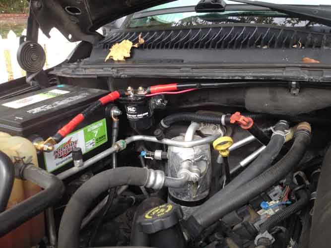
Hookups on the "house battery" side. The Stinger has 2 large posts that are for the positive connections to each battery and two small posts. One of the small posts goes to ground and the other goes to a powered circuit, to open and close the switch. It doesn't matter which one of the small terminals is used for ground and which one for the switch, they're interchangeable. In this photo I've connected the + cables but not the - or the switch to the Stinger. As you can see I used the Blue Sea side terminal fuse holder, just like Jelorian. I used 150a fuses on both ends.
.

.
Final setup of the house battery with all wires connected. If I was more picky I might have used black wire for the ground connection and red for the power connection, but I had a bunch of yellow so that's what I used. :sombrero:
.

.
A few notes about this: I used an extended side terminal bolt on the negative side, that had another bolt on the end of it. Both the negative/ground battery connection and the negative wire to the Stinger are attached to the outer bolt. The negative battery cable is also a 2awg welding cable with a crimp-on ring, the only difference is I wrapped it in black wire loom rather than red. The yellow wire that runs from the negative terminal to the stinger uses ring connectors on both ends. The negative attaches to the small post closest to the front of the vehicle (closest to me in the photo) and the yellow wire that runs from the rear small post on the Stinger is the power wire for the switch that runs to the fuse block.
.
You can see that I routed the large negative battery cable (black wire loom) underneath the Stinger....
.

.
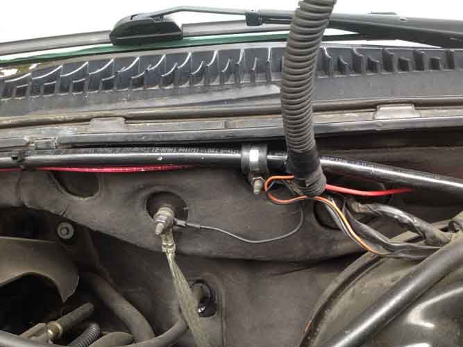
...and connected it to the same bolt as the chassis grounding strip behind the engine. The yellow wire is the power wire that goes to the fuse box.
.
And here's the fuse box (sorry for the fuzzy photo, it was getting dark and my camera was having a hard time focusing.)
.

.
I used an add-a-circuit and went into the same 10a ignition fuse slot that Jelorian used on his. Wire is routed underneath the fusebox.
.
After I got everything buttoned up and bolted down, I started the truck. Measured 14.5 volts at the starter battery and about 14.25 at the house battery - I'm assuming that means the system is working as the house battery appears to be receiving a charge?
.
Anyway, I thought some of you with GMT-800 vehicles might like to see my writeup, so here it is. Nothing too fancy, I basically copied Jelorian's but I did just a few things differently.
.
On some dual battery setups, the hard part is figuring out where you're going to shoehorn in a 2nd battery in an already crowded engine compartment. But, since the GMT-800 trucks had an option for a 2nd battery on the passenger side near the firewall, that part is easy: You just get the factory battery tray and replace the brace on the fender with the battery tray. It's a straight bolt on.
.
.
As you can see from the photo, I put the crescent-shaped hood brace back on because I wasn't putting the battery in right away (I got the tray back in June or July.) In order to put the battery on, though, that brace has to come off.
.
Next I had to figure out where and how to mount the isolator. I went with the same 200a "Stinger" isolator that Jelorian used. I was nervous about drilling into the firewall (because I wasn't sure what was behind it - didn't want to hit a heater line or something) but it was no big deal. Instead of using sheet metal screws (which I was worried would loosen), I went with "jack nuts." For those who have never used jack nuts, they're pretty cool. Basically it's similar to the idea of a molly bolt, you drill a hole, then put the jack nut into the hole, then use a special tool to expand the back of the jack nut which then grips the sheet metal. In essence, it puts a nut on the "blind" side of a piece of sheet metal that you can then put an actual screw or bolt into.
.
Located where I wanted the holes and drilled for the jack nuts:
.
.
Jack nuts in place:
.
.
Once the jack nuts were in, I bolted in the isolator using machine screws, washers and lock washers.
.
.
Once that was done I turned to my cables. I got 20' of 2AWG welding cable from a local welding shop and some large ring terminal ends. I don't have shrink wrap, a soldering gun or any fancy crimping tools...but I DO have a bench vise!!
.
.
I'll bet I use the vise more than any other tool I have! It's awesome for having a 'second set of hand' to hold onto things while I work on them. Got the ends crimped on...
.
.
Then sealed with electrical tape...
.
.
I know some of you use shrink wrap but for me the "redneck" style tape will work.
.
My biggest expense (and the one thing that kept me from getting this done months ago) was sourcing the battery. I went with this from the local Batteries + Bulbs outlet.
.
.
It's a group 34/78 (i.e. it has both side AND top terminals) deep cycle AGM, rated at 68ah. That's quite a bit more than my starter battery (also an AGM) which is rated at 55ah. It was very expensive (about $280 OTD) and while I was sorely tempted to go with a cheaper battery just to get this done, I thought, "No, I only want to do this ONCE." The battery fit perfectly in the tray.
.
On the "starter battery" side instead of using a quick-release (as Jelorian did) to get enough extension to reach the positive side terminal (it's kind of buried in there!) I used a marine terminal on the top terminal of my 34/78 starter battery.
.
.
The reason I went with this was simple: Because I already had the marine terminal adapter. The only 'downside' of this is that I did have to remove the metal rod brace that runs diagonally across the top of the battery (GMT - 800 owners will know what I'm talking about.) I don't really know that the brace is even necessary. If I decide to use an extended side terminal adapter as Jelorian did, I can put the brace back but for now I think this works.
.
You can also see that I wrapped the positive cable in red wire loom. Not really "needed" as the 2awg wire has a very thick insulator, but I wanted to be able to tell + from - at a glance and since the cables were all black, this was the best way to do it. It also lessens wear and tear on the cable.
.
Hookups on the "house battery" side. The Stinger has 2 large posts that are for the positive connections to each battery and two small posts. One of the small posts goes to ground and the other goes to a powered circuit, to open and close the switch. It doesn't matter which one of the small terminals is used for ground and which one for the switch, they're interchangeable. In this photo I've connected the + cables but not the - or the switch to the Stinger. As you can see I used the Blue Sea side terminal fuse holder, just like Jelorian. I used 150a fuses on both ends.
.
.
Final setup of the house battery with all wires connected. If I was more picky I might have used black wire for the ground connection and red for the power connection, but I had a bunch of yellow so that's what I used. :sombrero:
.
.
A few notes about this: I used an extended side terminal bolt on the negative side, that had another bolt on the end of it. Both the negative/ground battery connection and the negative wire to the Stinger are attached to the outer bolt. The negative battery cable is also a 2awg welding cable with a crimp-on ring, the only difference is I wrapped it in black wire loom rather than red. The yellow wire that runs from the negative terminal to the stinger uses ring connectors on both ends. The negative attaches to the small post closest to the front of the vehicle (closest to me in the photo) and the yellow wire that runs from the rear small post on the Stinger is the power wire for the switch that runs to the fuse block.
.
You can see that I routed the large negative battery cable (black wire loom) underneath the Stinger....
.
.
...and connected it to the same bolt as the chassis grounding strip behind the engine. The yellow wire is the power wire that goes to the fuse box.
.
And here's the fuse box (sorry for the fuzzy photo, it was getting dark and my camera was having a hard time focusing.)
.
.
I used an add-a-circuit and went into the same 10a ignition fuse slot that Jelorian used on his. Wire is routed underneath the fusebox.
.
After I got everything buttoned up and bolted down, I started the truck. Measured 14.5 volts at the starter battery and about 14.25 at the house battery - I'm assuming that means the system is working as the house battery appears to be receiving a charge?

")