Dual Battery Installation in LR3

jerdog53

Explorer
I set out this summer wanting to run dual batteries for I felt a lot of reasons. Refrigerator operation, winching, Ham radio power and to provide juice for all those sundry electronic devices we accumulate. Did some research on line and read some forums and decided on the D3-DU kit from Traxide in Oz and was very pleased with what arrived. It wasn't until this last weekend I had time to attempt the install.

http://www.traxide.com.au/complete-...y-3-dbs-kits/d3-du--usi-160--abg-25--fpc.html

The instructions that came with the kit are a little confusing and wordy at times compared to the aerospace work instructions I'm used to but none the less got it figured out and installation went as follows.

Access the driver's side of the truck by removing the B pillar lower trim panel then the drivers and passenger sill trim piece.

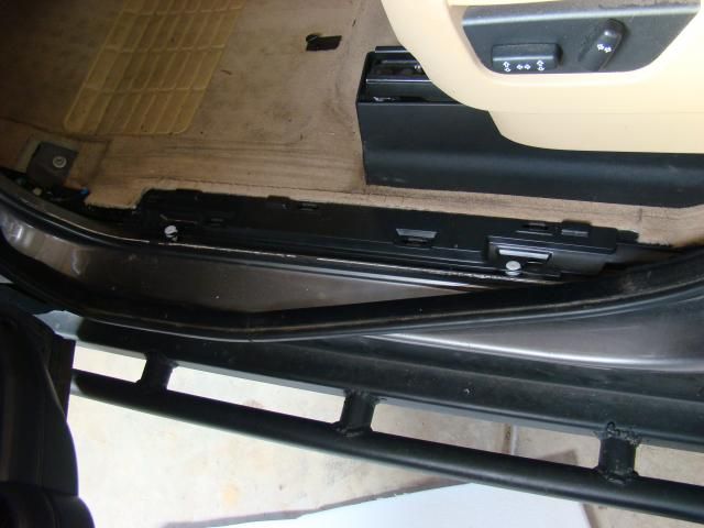
The drivers foot rest needs to be removed by popping the center portion off than unbolting it from the floor. Next is the drivers kick panel held in with clips. Peel up the outboard side of the door seal and remove it enough to pry up sub-floor I guess you could call it revealing the wire harness trough underneath.

DSC05136_zpsf96550de.jpg


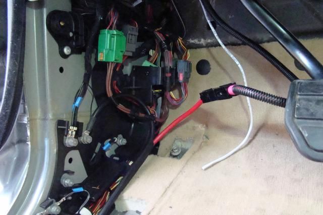
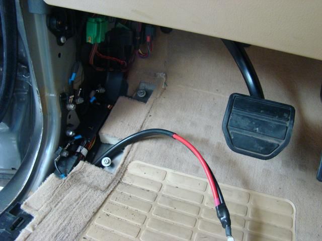
Starting from the kick panel lay in the long power feeder from the front to the rear and tuck it into the wire harness trough.
DSC05137_zpsca7bee54.jpg


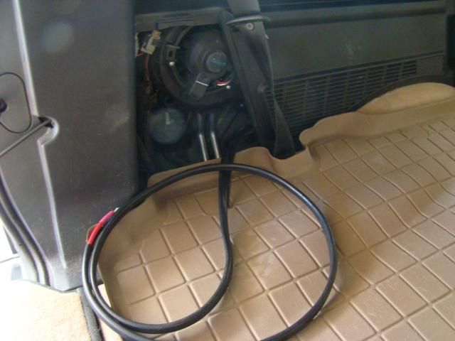
Route the feeder wire up under the lip of the heater box along the floor of the cargo area drivers side and pull out the wire through the hitch storage compartment .
DSC05140_zps02d493c7.jpg


Gain access to the back side of the OEM power port in the right rear cargo compartment by popping the clips and pulling the heater box inboard.
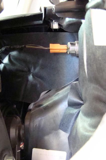
DSC05148_zps08443a0a.jpg


Remove the OEM wire connector and replace with the supplied two wire harness from the kit route out through the hitch storage compartment.
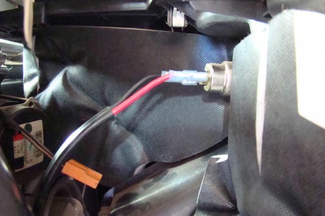
DSC05150_zpsfcbe16db.jpg


Next decide where you want the second power port installed. The kit gives instructions for the passenger side in the rear, I chose the forward drivers side being as I had the heater box mostly disconnected.
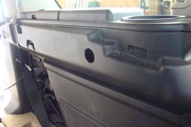
DSC05164_zpsca2b2710.jpg


Open up a hole and connect the other end of the supplied two wire harness from the hitch storage compartment to the second power port and install.
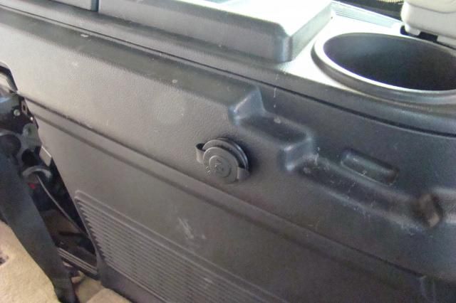
DSC05166_zps992bfcb1.jpg
 

jerdog53

Explorer
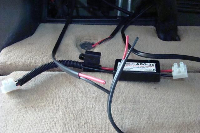
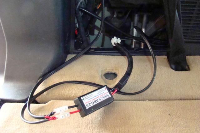
Pull the supplied two wire harness back out the hitch storage compartment and locate the end of the spare leg spliced off the main power feeder harness and grab the short AGB-25 harness from the kit.

DSC05167_zps5486b6b9.jpg


Cut, strip and connect the two power ports into one end of the AGB-25 and the one end of the spare leg into the other.

DSC05170_zpsfa152c30.jpg


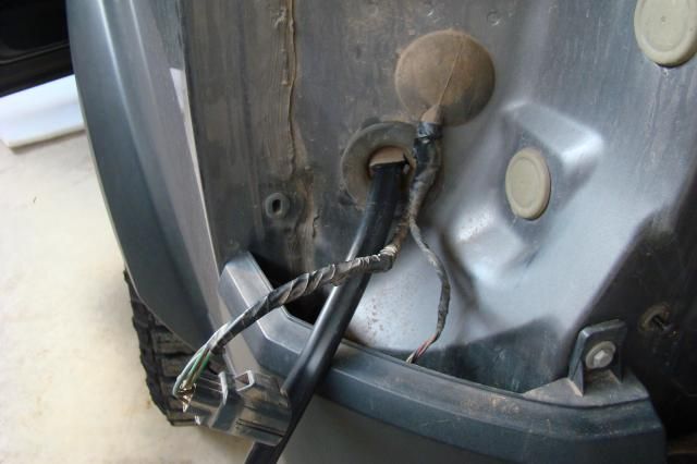
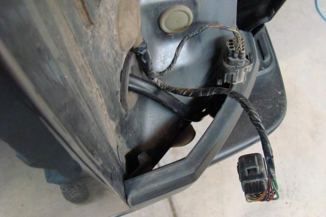
Remove the drivers tail light assembly and the two grommets, open up holes in the grommets and route the main power feeder thru the inside grommet noting the orientation of the grommet.

DSC05157_zpsa8d8bd68.jpg


Route the power feeder thru the opening in the body and out the tail light location and install both grommets.

DSC05159_zps11cc4d0e.jpg


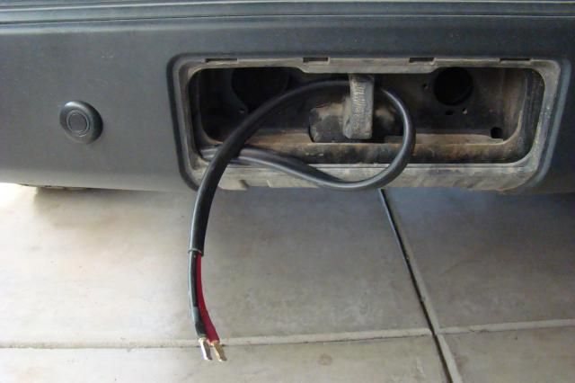
Run the power feeder behind the bumper cover and out the recovery ring access cover.

DSC05158_zpsad706e83.jpg


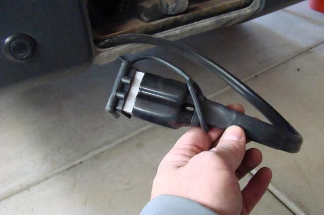
Install the Anderson Connector with heat shrink and dust cover.

DSC05163_zps263741fd.jpg


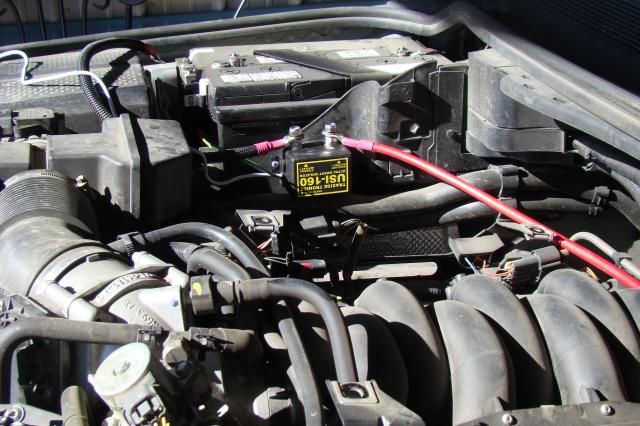
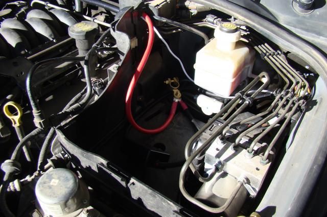
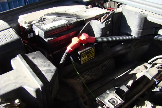
Under the hood locate and install the control box to the inboard of the outside of the starting battery box or a location of your choosing based on cable lengths.

DSC05173_zps80aeceac.jpg
 

jerdog53

Explorer
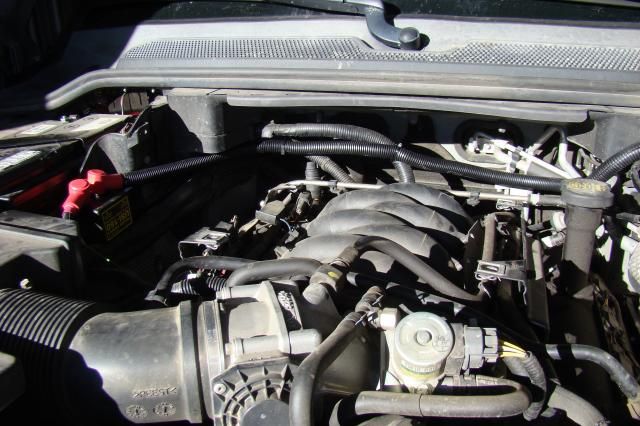
Route the auxiliary battery power cable and white 4 wire lead inside its protective covering across the back of the engine compartment to the aux battery compartment on the drivers side.

DSC05180_zpsfe7493b6.jpg


Remove the tiny hidden grommet from the outboard side of the break booster. Route the Anderson connector end of the short harness thru the grommet with the white 4 wire lead from the controller thru the hole in the firewall and out under the dash.

DSC05181_zps7517083d.jpg


Build up and connect the Anderson connector the main power feeder at the driver's kick panel.

DSC05175_zpsd0a94b90.jpg


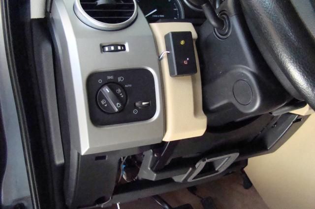
Find a nice out of the way spot and install the switch box after connecting the 4 wires from the white lead.

DSC05176_zpsc51fc41e.jpg


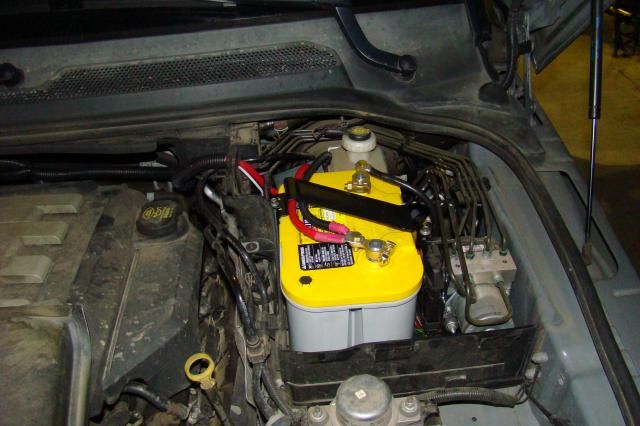
Install your group 34 battery with the supplied tie downs from the kit and connect.

DSC05184_zpsb8a7f657.jpg


Tidy up any loose ends and reinstall all your removed panels.

DSC05178_zps3c1028ea.jpg


Total install time for me and my learning curve was 5 hours roughly so if you're not very mechanical plan on all day.
No complaints!
 

flyingwil

Supporting Sponsor - Sierra Expeditions
Looks good. Sometimes it's a pain to install some of these things, you did a great job. You may want to inquire with them about the relay/control box possibly being mounted upside down near your passenger side battery. At our shop we've have a handful of customers rigs in for service to diagnose the dual battery systems and it ends up that sometimes with the units being installed upside down causes premature failures from being mounted in the wrong direction.
 

jerdog53

Explorer
nice write up with pics. Plan on doing this early next year.
What is the switch for?

The switch controls the operation of the solenoid. 5 different modes including Shared mode, Ignition mode, Jump start mode, Winch mode and Low power mode.
 

jerdog53

Explorer
You may want to inquire with them about the relay/control box possibly being mounted upside down near your passenger side battery. At our shop we've have a handful of customers rigs in for service to diagnose the dual battery systems and it ends up that sometimes with the units being installed upside down causes premature failures from being mounted in the wrong direction.

Thanks!

The install instructions state RH drive units have the solenoid installed with the poles down LH drive units have the solenoid installed with the poles up.
 

iowalr4

Adventurer
Does that switch box come with all of the kits now? What exactly does it do?

I just sent another email to traxide friday asking about a kit. I need to get this done before my trips next year.
 

DiscoNels

Adventurer
Remove the tiny hidden grommet from the outboard side of the break booster. Route the Anderson connector end of the short harness thru the grommet with the white 4 wire lead from the controller thru the hole in the firewall and out under the dash.

DSC05181_zps7517083d.jpg

Where EXACTLY did you run the wires thru the firewall, there is some elusive hole there apparently that nobody but a select few can access. I see the main bundle of wires (size of a garden hose or so) and one or two others that are being used and look pretty sealed.

It's not possible from you photo to see the actual entry point. Got any close up pics from the inside and outside you could post?
 

DiscoNels

Adventurer
Is it the small unused grommet that is to the upper left of the huge bundle going in? If so, that is basically NOT accessible from the engine side and from the inside it is not visible. Pictures people, pictures!!!!
 

Colin Hughes

Explorer
Yeah, I was looking for it on the weekend and couldn't locate it. A good bright light at my friends shop yesterday and I see it. It is up near the top of the firewall and the grommet is about the size of a quarter, if I've found there right one ��
 

unseenone

Explorer
Here is some pictures gang. You need to loosen the plate that holds the bundle of wires. Don't lose the NUT. Don't cut the zip ties, that will free it up so you have more room to maneuver. You'll then be able to remove the rubber grommet, set it aside for later. Then you should use a flat blade driver to make a hole, poke it through to cabin. Ground it out a little. Leave the driver in place, get on the floor, remove any protective covers, and use a flashlight to locate the screwdriver. Once you have located it, use a fine wire of some kind, attach it to the screwdriver, fish it back into the engine compartment. Two people help, one can feed it in, and one can gently pull from the engine side.

Once you have the fish line in, use it with some electrical tape, etc. Cut a "blade" or "V" into the end of the wire going in. Use the fish wire, and tape to tape securely to the wire. Reverse the process, and the person on the engine side, fish in, while the person in the cab pulls gently. Repeat as necessary. (LOL)

When you're done, you'll engineer to grommet to fit the wire, and feed it on, then get it started. By gently pushing and pulling from the cabin side, you should be able to get the grommet to snap into place. Again, repeat as necessary.

I hope this helps.. You'll find tons of pictures here in the Traxide SC80 section, Solar Section, Ham Section and so on.

http://www.disco3.co.uk/gallery/index.php?cat=11463

The batteries I'm currently running are European Style. Deka 9A94 Starting and Deka 9A47 Accessory/House. These will fit the factory brackets, and are the best I've found so far. If you are installing a battery in the Boot, then I would probably run two 9A94s. I've shelved my yellow tops, Interstate, etc. It is important to have both batteries in good shape. Don't throw in some old junk battery and expect good results. If you are in my area, I can get them for you.

A couple of quick tests you can do, is to use a multimeter to check the voltage on the starter battery, with everything connected and assuming a full charge. What's the voltage? Now disconnect the 2nd battery, check the voltage again, and check the voltage on the 2nd battery. If the 2nd battery doesn't hold a charge, of equal or greater, you probably need to evaluate the batteries, or run them both through a full cycle on a ctek and re-evaluate.
 
Last edited:

Forum statistics

Threads
188,360
Messages
2,903,719
Members
230,227
Latest member
banshee01
Top