Having trouble with CS130D not charging after hooking up isolator, help!

Meili

Adventurer
The wiring on my S10 is a disaster, as I slowly do more projects to it they get fixed.

The CS130D(round) had a CS130(square) plug jammed into it, no fusible links, bad connections etc etc.

All that has been repaired. Took a while to get the charging system ironed out but I finally got it working well, picked up almost 2 volts!

That was until I wired in a basic 3 terminal battery isolator. Hard to screw that up.

If I disconnect the original charge wire from the alternator, it is hot/live, there is no output.

Seems like it "needs" voltage to the charge wire to excite?

I can run a switched 12v supply to the charge terminal. It will work but that defeats the purpose of the isolator, creating a loop when the key in on.

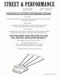
The alternator is now wired like the attached diagram using the correct plug:

S terminal (blue) to remote power block

I terminal (green) wired to switched 12v

P & L (white & yellow) are not used

Ideas?
 

Attachments

  • CS130D.gif
    CS130D.gif
    55.4 KB · Views: 11
Last edited:

DiploStrat

Expedition Leader
...

That was until I wired in a basic 3 terminal battery isolator. Hard to screw that up.
...
Ideas?

Ideas? Sounds like you are trying to use a classic diode isolator. For reasons discussed into the ground on this forum, get rid of it, and go with a switch. Your choice, manual, ignition controlled, intelligent. Wire everything up with properly sized wires and all will be well.

But one of many discussions of the weaknesses of diode isolators:
http://www.smartgauge.co.uk/diodes.html
 

HenryJ

Expedition Leader
What year is your S-10?
You might find my charging journey helpful: S-10crewcab.net - Bigger Alternator
You will find missing images and links that may no longer work as that thread is a dozen years old now.

"Wiring the regulator:
The regulator has four pins.

The big wire is the sense wire. Labeled "S". It is used to remotely sense the voltage instead of measuring it from the alternator itself. This would be run to the power distribution center or battery if needed.
The next wire is supposed to be the "I" or ignition feed wire. This receives 12v to start the regulator. This basically turns on the alternator. It may be labeled "I/F".
Next to that one is one labeled "L". This should go to a light.
The last small one is labeled "P" and can be used as a tachometer signal. It is a pulse generator. "


Ok, so properly wired a generously sized cable runs to the diode based isolator from the positive post on the back of the alternator. Do not operate or "test" this disconnected. A shunt is required for testing.

The big sense wire on the regulator is not used or can be looped to the back of the alternator if you are worried about the internal sensing. That wire is designed to go to the battery where the regulator can use that remote location as its reading for voltage regulation.
You do need the ignition wire to the regulator. That tells it when to start and when you have stopped.
The other two are not needed unless for a light and tach or hour meter.

Wow, really? I only need one wire to run the alternator regulator? Yes :) Just the ignition.

A couple suggestions. Ground, Ground and when you are done....add another ground. Good size cables to each frame rail from the engine. From the frame to the cab, from the cab to the engine. Ground the distributor housing to the engine. A clamped wire around the shaft housing to a intake or valve cover bolt. (known issue with module failures)

Upgrade the headlamp wiring with relays and nice size power wires. having full voltage to the headlamps will greatly improve them. The stock wiring will not do the job.

Now back to the isolator. Hopefully you get it working, but don't spend too much time on it. Here WAS mine:

isolator.JPG


Notice I say, was... I replaced it with an ignition activated solenoid for charging. Very simple , easily tested and has proved to be more reliable. That was done many years ago and I live happily ever after :)
 

Meili

Adventurer
It's a 1985 S10 extended cab 4x4 , 350, th700r, 4.10 gears.

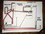
Don't laugh at the crude diagram attached, I just drew it up.

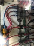
The Sense wire goes to my sub panel that controls the fog lights, drive lights, 2 cooling fans, air horn and one extra just in case.

I am more and more convinced it's the alternator. I believe I have it wired right, good wire, extra grounds etc.

If I remove the factory charge wire, looks like an L in the diagram, there is no output.
 

Attachments

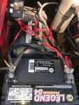
  • s10 power 6.JPG
    s10 power 6.JPG
    166 KB · Views: 4
  • s10 power 7.jpg
    s10 power 7.jpg
    71.9 KB · Views: 4
  • s10 power 8.jpg
    s10 power 8.jpg
    128.5 KB · Views: 3

Meili

Adventurer
I hate guessing vs knowing but decided to roll the dice.

Will be swapping in an AD244 later today.

At least I will pick up 30 more amps output!
 

HenryJ

Expedition Leader
You will not regret the AD244. If you are purchasing at a NAPA add HO to the part number and see if the have the High Output AD244 available. Mine was less expensive for the HO. Crazy.
The CS130D has a fatal flaw in that the bearing is supported by a plastic bushing. When heated this bushing regularly fails. The AD244 does not have this design flaw. The CS130D is rated at 105 amps. The stock vehicle in 2001 had that about maxed. any additional loads and an upgrade was needed.
For the bigger alternator you may need a longer belt if you are running the serpentine belt. I am pretty sure the information is in that thread from S-10CREWCAB.net. That stuff is V-6 , but the V-8 drive system and mounting is the same.

You have the sense wire connected at a sub panel. That can work. Make sure that it has some "shock absorption". That may not be the best analogy... It needs a place with limited swings in load. attached at a high drain point it may fluctuate radically. The battery acts as a shock absorber for loads and helps to calm the seas so to speak. Food for thought.

Question:
You have a battery disconnect switch between the two output posts on the isolator. What is its function? It appears that would defeat the isolator? Yet it does not function to bypass it. I am a little confused here.
Nothing is attached to one of the output posts on the isolator. Is the plan to add another battery some day?

If you are having problems still, suspect the isolator. Diode failures are not uncommon. When that time comes...replace it with a solenoid and live happily ever after :)
 

Meili

Adventurer
The switch is a "just in case" deal if the start battery dies. Hopefully will never have to be used. Yes, there will be battery bank attached to the isolator, in process of building right now. I got and hooked up the new alternator, it's worse , only 12 v output. I eliminated the isolator with no change. I am convinced it's the way the 4 conductor plug is wired but I have it wired the way the diagram in my first post shows. Looking for a tree to drive into.........
 

Meili

Adventurer
Looks like I was right that I was wrong on the 4 plug or visa versa.  I ran a jumper threw a dash bulb and everything works, even when the isolator is hooked up. That's what I get for trusting a diagram on the internet. Next is to unplug stock charge wire.
 
Last edited:

HenryJ

Expedition Leader
The switch is a "just in case" deal if the start battery dies. Hopefully will never have to be used. Yes, there will be battery bank attached to the isolator, in process of building right now.
Ah. ok. You will want larger gauge cables to combine the two batteries. Those wires from theswitch are not large enough to support the needed amp draw when you are trying to start the vehicle by combining batteries. I would keep them away from the isolator too. Those diodes don't like heat.

Sounds like you have it figured out GL :)
 

Meili

Adventurer
Nope. It works fine until the stock charge wire is disconnected.

Apparently newer alternator must "see" voltage at the charge wire output terminal.

I guess I will have to say "uncle" and get a continuous duty solenoid.

The not know why is really going to bug me.
 

DiploStrat

Expedition Leader
Apparently newer alternator must "see" voltage at the charge wire output terminal.

I suspect you are correct.

I guess I will have to say "uncle" and get a continuous duty solenoid.

Which, for all the reasons linked, is MUCH better.

The not know why is really going to bug me.

If you really must throw away 0.5v of charge, try connecting a wire from the positive terminal of your starter battery to the middle ("alternator") terminal of the isolator and your second battery to one of the other terminals, leaving the other unused. This will let your alternator "see" your starter battery and regulate properly. The feed to your second battery will be down about 0.5v, but you may be able to live with it.

I, on the other hand, would ditch the diodes.
 

Meili

Adventurer
"If you really must throw away 0.5v of charge, try connecting a wire from the positive terminal of your starter battery to the middle ("alternator") terminal of the isolator and your second battery to one of the other terminals, leaving the other unused. This will let your alternator "see" your starter battery and regulate properly. The feed to your second battery will be down about 0.5v, but you may be able to live with it.'

That way you can still kill your start battery, the start/alt feed the center, center feeds the house.

I did think about doing the opposite, house/alt to center and start to outside terminal, alt "sees" house for voltage.

This would charge both but not let the house draw down the start battery.

I hate when something so simple is a PITA!
 

dwh

Tail-End Charlie
"If you really must throw away 0.5v of charge, try connecting a wire from the positive terminal of your starter battery to the middle ("alternator") terminal of the isolator and your second battery to one of the other terminals, leaving the other unused. This will let your alternator "see" your starter battery and regulate properly. The feed to your second battery will be down about 0.5v, but you may be able to live with it.'

That way you can still kill your start battery, the start/alt feed the center, center feeds the house.

I did think about doing the opposite, house/alt to center and start to outside terminal, alt "sees" house for voltage.

This would charge both but not let the house draw down the start battery.

I hate when something so simple is a PITA!

The sense wire is fed by the engine battery.

The engine battery will be at proper voltage because the sense wire is sensing voltage *after* the drop through the diode. The voltage regulator will end up running the alternator a half volt high to make the voltage proper at the sense wire.

If you feed the house bank after the diode, it will be at the same voltage as the engine battery because it will have the same drop through its diode as the engine battery has.

If you feed the house bank *before* the diode, but the the sense wire *after* the diode, the house bank will end up a half volt high.
 

DiploStrat

Expedition Leader
OOPS!

...
That way you can still kill your start battery, the start/alt feed the center, center feeds the house.
...
I hate when something so simple is a PITA!

OOOPS! As you can see, I hate, loathe, and despise diode based systems. (And forget how diodes work from time to time!) A long sad story that left me with dead batteries in the freezing altiplano! Really.

Bottom line: Quit dorking around with a bad technology. GM installs a very robust charging system for lead calcium batteries. Use a relay and let it do its thing for both of your batteries.

Reread the link I posted; it explains why all diode systems, even those with sense wire provision, are less effective.

(The one exception is a true B2B, but in the case of GM vehicles, there is no reason to use a B2B as your voltage is already where it needs to be.)

Good luck!
 

Meili

Adventurer
dwh is 99% correct.

Only thing that is different from what he wrote is my sense wire reads my sub-panel to compensate for voltage drop/load.

The panel gets it feed from the isolator terminal, same terminal battery is connected to.

Just to drive DiploStrat crazy, I could add a diode to the stock charge wire at the back of the alternator.

The alternator would "see" the battery, but not backfeed, thus allowing the isolator to work as designed. ;)
 

Forum statistics

Threads
188,214
Messages
2,903,872
Members
229,665
Latest member
SANelson
Top