How to make a cheap isolated dual-battery setup for $50

Smith

New member
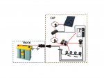
To better explain an above question...would this setup work to contain the solar setup to the cap of the truck? The battery would be my 2nd deep cycle battery under the hood, charged from the alternator via solenoid when the truck is running.

I'm only confused if the wiring of the positive is OK to just run both the solar array and the battery to the bussman fuse block to run powered items or if a separate line is needed directly from the battery? :confused:

Solar Setup.jpg
 

dwh

Tail-End Charlie
That'll work.

The wire from the battery to the fuse block will likely be larger than the wire from the charge controller to the fuse block, so once the power gets to the fuse block, it won't be restricted flowing to the battery.

It's all just one big "12v bus".


EDIT: Think of it in terms of compressed air. You are running a line from the air tank (battery) to a manifold (fuse block) and you have your compressor (charge controller) hooked up to the manifold instead of directly to the tank. Doesn't matter - the pressure (bus voltage) in the whole system, including the tank, is going to rise when the compressor kicks in.

EDIT AGAIN: You could even feed from the charge controller into the bus, by going IN through one of the fuses on the fuse block if you had a spare slot.
 
Last edited:

NW European

Observer
Thanks for this thread -- a much more entertaining way to look at this 2nd battery system with the pictures!

Maybe it is just late at night, but I cannot get my head around one thing – Let’s say that I was a lazy bastard, and wanted to use the 200A+ solenoid so that I did not have to get my jumper cables out of the trunk when my starting battery was dead. If the starting battery is dead, and I have a powered switch in the dash to “turn-on” my solenoid….how would it work when the battery on those circuits (assuming OEM fuse block to supply this switch power) is dead? Won’t I have to get my jumper cables out anyway? And if so, then why not just stay with the 80a solenoid set-up so I can have more beer money?
 

4RunAmok

Explorer
The power you use to manually engage your 200+ amp solenoid comes from your second battery, not your starting battery.
 

LandCruiserPhil

Expedition Leader
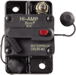
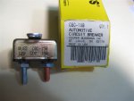
I use the same basic set-up in post #1 but breakers instead of fuses. Switchable for large circuits and auto resets for small circuits. Eliminates the need to carry spares.
 

Attachments

  • Circuit_Breaker.gif
    Circuit_Breaker.gif
    17 KB · Views: 3,090
  • breaker.JPG
    breaker.JPG
    38.3 KB · Views: 194
  • Like
Reactions: WVI

dwh

Tail-End Charlie
The power you use to manually engage your 200+ amp solenoid comes from your second battery, not your starting battery.

Yea.

Or, you could use a small wire and jump from the aux battery big post on the solenoid, to the + small post on the solenoid to energize the solenoid. As soon as the two batteries are tied, power will flow from the aux side to the primary side, and the solenoid will have power available to remain energized.
 

4RunAmok

Explorer
Well, if it were me, I'd have a 3 way switch on the dash.

Position 1 Normal operation, power to engage solenoid comes from vehicle accessory
Position 2 Manual Disconnect, solenoid disengaged, batteries isolated for whatever reason I might need to do so.
Position 3 Manual Connect, power to engage solenoid comes from second battery
 

RichardT

Adventurer
I started up a thread on this, asking about a dual battery set-up on the Mitsubishi forum. Just finished reading through the last 6 pages, and wow, some awesome advice and info, though I'm having a hard time wrapping my head around some of it.

I was hoping to set up my system so that when I'm camped, parked whatever, all my lights, an inverter for powering small appliances/plugging in cell phones what have you, would run strictly off of the 2nd battery(deep cycle), and be isolated from the main battery (regular battery). When I go to start up, the main battery would handle that, and as soon as I'm running, the alternator would be able to charge both the main, and secondary battery. As well as when I'm parked, the solar panel would supply a small charge to both batteries.

I borrowed a pic that Smith posted earlier, as this more closely resembled what I wanted to do, though, I wouldn't have that all weather connection between the yellow top and the fuse block for the accessories, but rather in between the solar panel itself and the controller, so that I could store the panel, and not need it permanently mounted.

Battery diagram.jpg

I hope the photo makes sense, my first attempt at a wiring diagram, I left out the fuses to keep it simple, but I'm assuming I would require one fuse between the alternator and the yellow top, but as it mentions in the photo, would I need an isolator specifically? Or could I accomplish this with just the solenoid?

And is it even possible to charge each both batteries off the solar controller, while still keeping them separate?

My main thing is I want to keep the main battery virtually isolated, except for charging it via solar, without any threat of draining it by using the extra accessories when parked, so that it's always charged and ready to go, even if I deplete the yellow top, so that I can either charge the yellow top, or head home.

EDIT: I'm thinking I may need a second solar controller for the main battery? Otherwise different power levels in each battery might confuse the one controller, supplying power when not needed, or not supplying it when needed?

Thanks in advance.
 
Last edited:

dwh

Tail-End Charlie
And is it even possible to charge each both batteries off the solar controller, while still keeping them separate?

Not with that charge controller. By adding the wire from the charge controller to the engine battery - you've just bypassed the solenoid and hard-wired the engine and house batteries together full-time.

Morningstar makes a charge controller specifically for the purpose you describe - the 'SunSaver Duo'.


EDIT: I'm thinking I may need a second solar controller for the main battery? Otherwise different power levels in each battery might confuse the one controller, supplying power when not needed, or not supplying it when needed?

Technically...once you've wired the two batteries together like in your diagram - it's just one big battery and won't confuse the controller at all.


You would have to use two controllers.

Morningstar does have an old doc laying around their web site which shows how to rig two single-battery PWM (won't work with MPPT) controllers to both take power from a single solar panel. Better to just buy the Duo.
 

RichardT

Adventurer
Not with that charge controller. By adding the wire from the charge controller to the engine battery - you've just bypassed the solenoid and hard-wired the engine and house batteries together full-time.

Morningstar makes a charge controller specifically for the purpose you describe - the 'SunSaver Duo'.

Thanks for that tip, I didn't know that anyone made something like that.

So, would my diagram how I described and pictured work? especially with the inclusion of the Duo? Meaning keeping the engine battery completely isolated from the house battery, but still able to receive a charge from the solar panel? And the house battery getting a charge by the panel as well as the alternator when my engine is running?
 

dwh

Tail-End Charlie
If you replaced the controller in that diagram with a Duo, and stuck a solenoid in there instead of a question mark :) - then yes, it would work.

Also, the wire from the aux battery to the alternator would run to the + terminal on the cranking battery rather than to the alternator (with the solenoid in between).
 

Forum statistics

Threads
188,158
Messages
2,902,808
Members
229,582
Latest member
JSKepler
Top