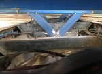
Mercedes 1222A.. The beginning!

Sitec

Adventurer
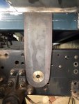
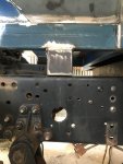
Next up is a support leg each side, so the bush only acts as a locator and pivot for the small amount of movement that will be here. The support leg has a piece of plate welded into its base, and that plate has a slight radius on it to allow for movement. The leg and bush on each side share the load. With the spare wheels, fuel and water tanks, batteries, generator and grey water tanks being mounted to the chassis, the body should be no more than 4 tonnes at the most, so an average of a tonne per mount is not huge.
Front Mt 3.jpg
 

Sitec

Adventurer
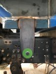
Lastly, weld it all up and put the bolt and washers in. I've made the bush 24mm wide. Both the chassis and the drop plate together are 24mm wide, so the bolt and washers are only there to support and secure the bush, whilst allowing it to move a little. There will be no grease points on these two mount points. The bolt will be double nutted though for security. I hope to start fabricating the middle pivot mount this week. I have left an accurate 100mm gap between the body rails and the chassis rails, so I can add 'rail on rail' support if this is a disaster!! :)

Front Mt 5.jpg
 

VerMonsterRV

Gotta Be Nuts
Hey, this question is solely for my learning about steel (I have no background with metal design and fabrication). Did you reinforce the hole in the chassis that the bushing is in? Sort of a plate that would have an identical sized hole that would bolt to the surrounding holes in the chassis to increase the surface area that the bushing rides in? Asking for any future changes we might need to do to our truck.
 
  • Like
Reactions: mog

Sitec

Adventurer
Did you reinforce the hole in the chassis that the bushing is in? Sort of a plate that would have an identical sized hole that would bolt to the surrounding holes in the chassis to increase the surface area that the bushing rides in? Asking for any future changes we might need to do to our truck.

Hi Jon.

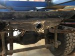
No, I didn't. Where that hole is, the chassis is double plated. Two stamped pieces of 6mm steel giving me 12mm of chassis to locate on. The bush is brass and being softer is the 'sacrificial' piece. As it's 60mm round it still has a reasonable surface area in contact with the chassis, and as there's a support leg behind the drop plate which supports the bulk of the body weight. The bush is more of a locator and pivot for minimal movement. However, it is a case of 'watch this space' with this bit of the build as I'm in unchartered waters. I figure by leaving the 4" gap between the body and chassis rails i have my 'get out of jail' card ready! :)
 

shade

Well-known member
Hi Jon.

No, I didn't. Where that hole is, the chassis is double plated. Two stamped pieces of 6mm steel giving me 12mm of chassis to locate on. The bush is brass and being softer is the 'sacrificial' piece. As it's 60mm round it still has a reasonable surface area in contact with the chassis, and as there's a support leg behind the drop plate which supports the bulk of the body weight. The bush is more of a locator and pivot for minimal movement. However, it is a case of 'watch this space' with this bit of the build as I'm in unchartered waters. I figure by leaving the 4" gap between the body and chassis rails i have my 'get out of jail' card ready! :)
I'm sure you'll carry spare bushes for field replacements. I know you're going to double nut those bolts, but if you'll have a small torch along, that would be an excellent place for some red threadlocker, too. If no torch, then blue.
 

Sitec

Adventurer
Another weekend, most of it 'playing truck'. I have managed to get the body sat on 4 points. Here is the start of the process. The diagonal supports.

Mid Mounts 1.jpg
 

Sitec

Adventurer
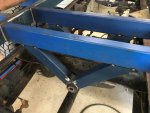
Those RHS supports will become part of the body, which will pivot on 2 (poss 3) of these base plates. Grease nipples yet to be fitted.

Mid Mounts 7.jpg
 

Sitec

Adventurer
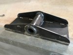
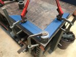
I've fabricated two of the base plates so they utilize two cross members on the chassis. The two that are linked directly to the spring hanger mounts of the rear axle. I figure that having the body supported on cross members that act directly on the spring hangers then leaves minimal load/stress on the chassis. Similar idea to having my front 'fixed' points close to the front spring rear hanger. These two mid cross members allowed enough room for a decent size pivot. Here's one in situ. Each base plate will be held in place by 8 M12 fine HT bolts.

Mid Mounts 8.jpg
 

Sitec

Adventurer
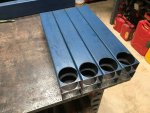
Next was to cut, shape and assemble the 4 'droppers' from the body to the base plate... which kinda went like this!

Mid Mounts 3.jpg
 

Sitec

Adventurer
With all 4 droppers fabricated and welded, it was time to move one poorly placed body X member (hard to plan this far ahead), and add 3 more. Once I had 4 X members in place I could position and tack the 4 droppers in place using the pivot pin to support and position them. Here is the first of the mid mounts done, the second mid mount was soon to follow!

Mid Mounts 4.jpg
 

Sitec

Adventurer
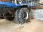
With both mid mounts in place, ideally I would have taken the truck outside and cross axled it on a few soil banks, but at the moment I have every air line from the battery tray/air tanks disconnected as I'm shifting the tray and tanks under the Pax door to give me more room for other stuff on the side of the chassis rails. (Ironically, this was it's original factory position before the crane was fitted). As the truck is not mobile, the bottle jack came out for a little test... Rear LH wheel approx. 300mm/12" off the ground (supported).

Mid Mounts 5.jpg
 

Sitec

Adventurer
And here's the picture of the chassis twist (Approx 50mm/2" up on the left rail and 50mm/2" down on the right rail). It should be noted that I can remove the pin locking bolts and tap the pins back and forth in the newly fabricated carriers, so I think I have the pivot points in pretty well the right place.

Mid Mounts 6.jpg
 

Sitec

Adventurer
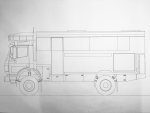
Sooooooo.... Question time. I have to chop the rear 600mm/24" off the chassis, which includes a nice factory riveted rear X member. I plan to reinstate the original rear X member flush with where the inner stepped section of the body finishes. This will put it approx. 1m/40" behind the rearmost of my new pivots. I'm thinking I'll add another pivot as I can, but don't think it really needs it. So, the question... My original plan was to have the side skirts/lockers etc mounted off the chassis and have a 100mm gap between the tops of them and the lower edge of the body (as per sketch below). I then changed my mind when I saw how much potential twist I could achieve and thought I'd hang it all off the base of the body (allowing the chassis to twist as much as it likes...How much is too much?), but after today's test (and seeing how much twist there was, still with 50mm/2" clearance between the chassis rails and body), I'm tending to think I go back to mounting the lower lockers/side skirts on the chassis, and then build in some little stoppers so that the chassis twist can only go so far, allowing the axle springs to do some of the work. With the twist test, the springs hardly moved!... If I get the stoppers right, the only close contact point under full twist will be the rear corners of the rear lockers. The spare wheels, rear bumper etc will be mounted on the chassis, and have the ability to lower to access/remove the spare wheels. Thoughts....

Side View (final).JPG
 

shade

Well-known member
I've never built one, so bear that in mind.

Keeping the lockers tied to the truck frame seems like a good idea. Simpler design, less stress on the pivoting frame, and you'll keep the gap that develops from frame twist up high at the deck level, instead of wherever the lockers end up. It seems like there'd be less chance of interference with a clean separation like that, too.
 

Forum statistics

Threads
188,161
Messages
2,902,887
Members
229,582
Latest member
JSKepler
Top