You are using an out of date browser. It may not display this or other websites correctly.
You should upgrade or use an alternative browser.
You should upgrade or use an alternative browser.
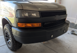
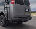
N.A.R.V. 2.0 - 2008 Chevy Express AWD Project (I'm back)
- Thread starter LYlqoY2Fo
- Start date
Pacific Northwest yetti
Expedition Medic
looks great!
LYlqoY2Fo
Builder
I just ordered by the part numbers, which I found elsewhere on the EP threads. The parts that I ordered needed to be ordered seperately. I ordered the keys from Summit Racing and Blocks/Shocks from 4 Wheel Parts.Hello!
I asked you on Insta today. Is your lift kit for Silverado trucks? Can’t find any parts for Express at the skyjacker hp. I‘m from germany, here it’s a little bit difficult to find a lift kit for my 2008 AWD. Can get a complete set including shock absorbers from Rough Country for ~350$. It’s for Sierra/Silverado trucks.
Thanks!
HeikoView attachment 588189
LYlqoY2Fo
Builder
The Interior Plan
I've been dropping the ball here and not keeping this updated. So prepare for a game of catch up.
Next up was planning for the interior. Something we learned from the Sprinter and NARV 1.0, is that we wanted something in the middle ground between just a van, and a full-on Vanlife rig. Our goal was to be a place to sleep, recharge gear, store gear, eat/cook, sit/eat, and pee (very important). Another thing we wanted was to ensure that we maintained 4-5 seats in DOT compliant seatbelts. It was a tall order for a regular van.
Here is the plan I came up with....
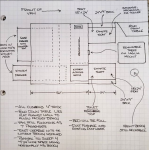
The bed will be Full Size North/South orientation. The front 24" of bed length, will be a small dinette, with the table being a removable/adjustable Lagun mount. Small dometic toilet will be under one dinette seat. About 1/4 of the under bed space will be for mechanical (inverter, AC/Heat duct, wiring, batteries, etc). The remainder will be two drawers; one wide (driver's side) and one deep/long (passenger side). The long one will be the main outdoor kitchen drawer and the wide one will be a gear drawer. There will be a top on back 16" or so of the wide drawer, so that when the kitchen drawer is fully extended and the gear drawer is 1/2 extended, there will effectively be a L-shaped outdoor kitchen with plenty of counterspace.
The first row bench seat will still be 100% usable, but when it is not in, there will be a fold up table from the driverside wall, which will allow for interior work space (e.g. cooking) if needed. BTW, both the kitchen and gear drawers will be accessible from the inside.
Beside the bed will be built in cubby storage (not shown on drawing). The passenger side will only come up to the rear window, so as to not block view when driving. The driverside will have cubbies and a wall that extends to the ceiling, blocking that rear window (which is not used when driving anyway).
There will be USB and 12v outlets throughout, particularly right behind the drivers seat for 1) passenger use when the bench is in and 2) 12v fridge use when the bench is out.
The floor in front of the bed will be made as wide as possible, and will have about 48" from the dinette to the front seats, making that entire area still large enough to carry furniture and in a crunch, be able to sleep two more on the floor (East/West). This area will be covered in Rubber flooring and trimmed in aluminum for durability.
The Rear AC/Heat will be kept, but the foot duct will be re-routed to a new vent in the foot area of the dinette.
So...in the end, it should be able to: Still use the factory bench. Seat 7 (5 in seatbelts) with the bench in. Sleep 4 with the bench out. Still carry furniture/large items. Still carry full sheets of plywood. Be packable with nothing rolling around on the floor. Sit 2-3 at a small dinette.
HINT: It does do it all (as I'm already done with most of it) and it is just about the perfect floorplan for a standard, IMO.
I've been dropping the ball here and not keeping this updated. So prepare for a game of catch up.
Next up was planning for the interior. Something we learned from the Sprinter and NARV 1.0, is that we wanted something in the middle ground between just a van, and a full-on Vanlife rig. Our goal was to be a place to sleep, recharge gear, store gear, eat/cook, sit/eat, and pee (very important). Another thing we wanted was to ensure that we maintained 4-5 seats in DOT compliant seatbelts. It was a tall order for a regular van.
Here is the plan I came up with....

The bed will be Full Size North/South orientation. The front 24" of bed length, will be a small dinette, with the table being a removable/adjustable Lagun mount. Small dometic toilet will be under one dinette seat. About 1/4 of the under bed space will be for mechanical (inverter, AC/Heat duct, wiring, batteries, etc). The remainder will be two drawers; one wide (driver's side) and one deep/long (passenger side). The long one will be the main outdoor kitchen drawer and the wide one will be a gear drawer. There will be a top on back 16" or so of the wide drawer, so that when the kitchen drawer is fully extended and the gear drawer is 1/2 extended, there will effectively be a L-shaped outdoor kitchen with plenty of counterspace.
The first row bench seat will still be 100% usable, but when it is not in, there will be a fold up table from the driverside wall, which will allow for interior work space (e.g. cooking) if needed. BTW, both the kitchen and gear drawers will be accessible from the inside.
Beside the bed will be built in cubby storage (not shown on drawing). The passenger side will only come up to the rear window, so as to not block view when driving. The driverside will have cubbies and a wall that extends to the ceiling, blocking that rear window (which is not used when driving anyway).
There will be USB and 12v outlets throughout, particularly right behind the drivers seat for 1) passenger use when the bench is in and 2) 12v fridge use when the bench is out.
The floor in front of the bed will be made as wide as possible, and will have about 48" from the dinette to the front seats, making that entire area still large enough to carry furniture and in a crunch, be able to sleep two more on the floor (East/West). This area will be covered in Rubber flooring and trimmed in aluminum for durability.
The Rear AC/Heat will be kept, but the foot duct will be re-routed to a new vent in the foot area of the dinette.
So...in the end, it should be able to: Still use the factory bench. Seat 7 (5 in seatbelts) with the bench in. Sleep 4 with the bench out. Still carry furniture/large items. Still carry full sheets of plywood. Be packable with nothing rolling around on the floor. Sit 2-3 at a small dinette.
HINT: It does do it all (as I'm already done with most of it) and it is just about the perfect floorplan for a standard, IMO.
Last edited:
LYlqoY2Fo
Builder
Floor framing and insulation
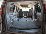
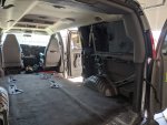
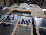
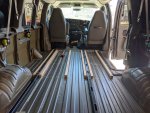
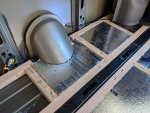
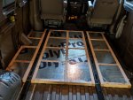
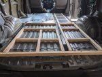
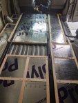
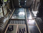
This took some thought and planning, as I needed to ensure that my final floor height would align with the bench seat mounts. It turned out that 2x2s + 23/32 plywood + rubber flooring would match up PERFECTLY.
I framed the floor in two sections; front then back. The opening you see is for the mechanical area, in which I will be routing things through the floor. It too will have a wood floor, but that will not happen until electrical is done.


Last edited:
LYlqoY2Fo
Builder
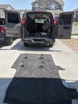
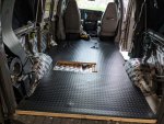
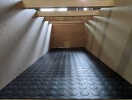
Rubber Floor installation
This was probably my most asked about item in Instagram. How, Where, etc?
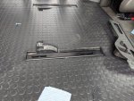
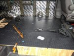
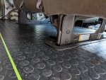
The material I used was the G-Floor Coin flooring. You can purchase it from lots of places; Walmart, Menards, (sometimes) Costco, etc. This is the same as I used in my Sprinter built. It has pros and cons. Pro is that it is relatively inexpensive and provides a very nice finish. Con is that it is COMPLETELY smooth on the back, which makes gluing difficult. The best product to use IMO, is the TPO coin flooring from RBcomponents, as it has a felt-like back added during manufacturing which glues very nicely....problem is, it is a little spendy.
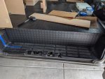
Learning from my past mistakes with this, I know that this flooring will expand/contract with heat. With that knowledge, the entire interior was planned so that 1) the floor would not be glued and 2) all edges would be trimmed in aluminum to allow that expansion and contraction without exposing the subfloor.
Anywhere that the flooring was used that required gluing (e.g. vertical surfaces), I prepped the back of the floor by scoring it with 60 grit sandpaper, to create surface area for the glue (3M 90) to adhere to. It has worked perfectly.


Last edited:
LYlqoY2Fo
Builder
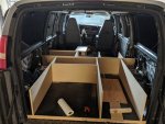
Bed Platform (basic framing)
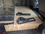
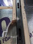
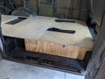
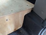
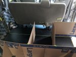
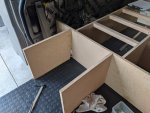
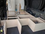
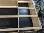
For this, I used 3/4" Particle board. Reasoning is, that all of this will be covered with rubber and it cuts and glues VERY straight. With this essentially being the foundation, I wanted it 100% solid. Every joint was screwed with pocket screws and glued. Anywhere wood touched metal, a foam barrier was put between them to avoid squeaks. This was also true of the floor construction; it too was all glued/screwed, and a foam barrier is between all wood and metal.
The height of this portion is 14" off of the floor. During the mockup, we decided to shorten the bed length a few inches to make getting in/out easier when the bench is in, and to make is "flow" a little better.
The cross members you see, are 2x2s and simply just spread out to distribute the bed weight...nothing fancy.
This entire structure was attached to the floor assembly with L-brackets throughout. It is EFFN solid and is not moving. Also...there is not a single squeak.
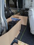
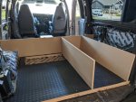
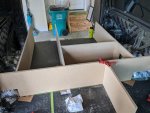
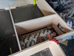


Last edited:
LYlqoY2Fo
Builder
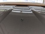
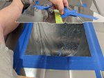
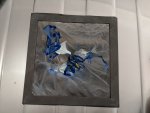
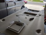
Headliner removal and the dreaded fan hole cut.
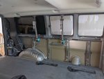
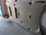
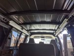
My original plan was to do everything with the headliner in...but the more I investigated, the more I realized it needed to be better insulated....so out it came.
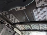
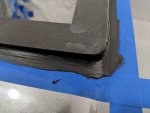
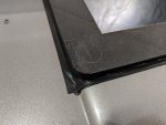
Removing the headliner is not hard at all, just ensure you have the body panel pliers (from Harbor Freight) and take your time. With the headliner out, it was time for sound deadening and "the hole".
For the Express, I HIGHLY recommend purchasing the fan mount adapter from ImpactProducts. It adds some cost to your project, but it will make the job SO much easier and cleaner. I followed their instructions exactly, using brush on FlexSeal, rather than Dicor Lap. After doing it this way, I wish I would have done my Sprinter the same. It is SO much nicer.


Last edited:
LYlqoY2Fo
Builder
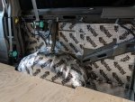
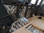
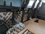
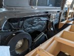
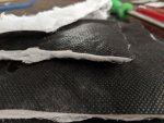
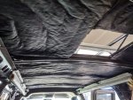
Thinsulate Insulation
Insulation in the vanlife world is a much disputed topic. I decided to go with Thinsulate, just as I did in my sprinter built. IMO, it is the easiest to get the best results with. I toyed with using Havelock wool...but the Thinsulate is SO easy. Cut, spray, stick, drink.
I purchased my thinsulate from ImpactProducts on ebay. I bought 35 linear feet, and it was plenty. If you are doing a cargo, you'd likely need 45-50.
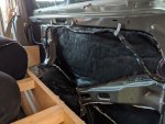
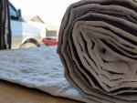
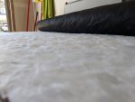


Last edited:
LYlqoY2Fo
Builder
Headliner Reinstallation, Ceiling Light Install, and Fan Mount
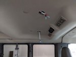
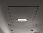
With the headliner down, it was time for more holes. 2" holes were made using the Dremel for 4 flush mount puck lights. All wiring was routed along with factory wires on the headliner and fastened down where needed. The goal was to ensure NOTHING moved or caused any sounds.
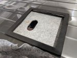
With the wiring complete, we reinstalled the headliner, which made marking the hole for the 14x14 fan hole simple...just drill down from the roof, connect the dots and cut it out. The fan was positioned so that it was about 3/4" from the back cross bar in the ceiling. This location would center it nearly perfectly over the bed, and is a very flat spot in the headliner.
Next, I installed the MaxxAir Deluxe fan mount, sealing it in with a few coats of FlexSeal. Like I explained when cutting the fan hole below, I HIGHLY recommend the roof adapter from ImpactProducts. Now to let it cure a day or so.
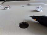
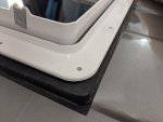
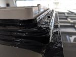
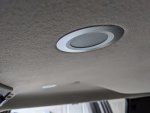


Last edited:
LYlqoY2Fo
Builder
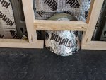
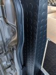
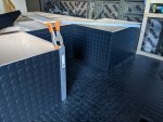
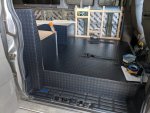
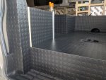
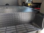
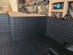
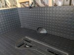
Remaining Wall structures in Front Area and Rubber Flooring on Vertical Surfaces
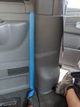
Behind the drivers seat, I framed wall structure using 2x2 lumber. This was designed to provide a solid surface for the face, mount the small countertop to, support the folding table and hinge. You will notice that it was made to allow the factory seatbelt to function as normal.
For the passenger side, the bed platform extends into the side door well, slightly. Here a structure was created to fit the factory body panel lines and to function as part of the dinette back rest support.
All of these surfaces were covered in the coin flooring, all scored with sandpaper and glued with 3M 90.
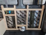


Last edited:
LYlqoY2Fo
Builder
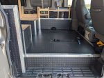
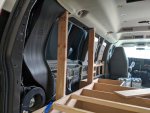
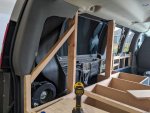
Aluminum Trim Work and Vertical Wall Structure by Bed
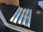
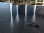
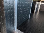
All of the coin flooring was trimmed out using aluminum. This really finished it off and I'm happy how it turned out. I used 1.5" aluminum to allow the coin flooring more room to expand and contract underneath it.
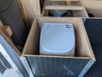
On the passenger side you will see the dometic toilet in its final location. The front panel of the toilet compartment will be held in by using the aluminum. This will allow removal of the panel vertically for using the toilet.
As for the rear wall structure. This was done with 2x4s, and attached to the bed platform base. 2x4s were used for strength and to avoid any flex when the cubbies were loaded with gear. On the passenger side (with the string) below, you can see where that wall structure will end. Just like was done everywhere else in the build, anywhere where wood and metal would have touched, a foam "squeak insulation" was added between. None of this is attached to the van, only to the floor and bed structure.


Last edited:
Similar threads
- Replies
- 5
- Views
- 2K
- Replies
- 3
- Views
- 1K
- Replies
- 3
- Views
- 3K
- Replies
- 131
- Views
- 110K


