You are using an out of date browser. It may not display this or other websites correctly.
You should upgrade or use an alternative browser.
You should upgrade or use an alternative browser.
New Build Begins- 2021 CV 515
- Thread starter 2 bikes 2 brown dogs
- Start date
DeepSeaDiver
New member
Amazing build! Four questions, if you can spare the time:
1. Overall height?
2. How did you get the International CV truck’s speedometer calibrated for the larger tires?
3. Did you have to change the axle gear ratios to accommodate the larger tires?
4. What impact have the tires had on the truck’s handling (acceleration, braking, tracking, ride comfort, etc.)?
Keep up the great work!
2 bikes 2 brown dogs
Active member
Hey Deep!
1. Overall height is unfortunate. 11'-11" to top of roof skin. Roof AC unit brings that to 13'-2". It's bad. BUT......We've got 6'-0" head room in the kitchen (above the tanks) and that turns into enough room to sit up in the loft.
2. The speedometer isnt calibrated yet (unless you count me multiplying the speed by 1.25 in my head as 'calibration'). Kidding. The upfitter that did the super single conversion thought there would be a module released by the time they finished and that wasn't the case. I bought the truck out of state but the local service center nearest me is a Rush Truck Center. I spent a good amount of time talking through options with them about a year ago and it seemed like calibrating was a dead end there. Rushg suggested reaching out to someone that services Allison's and try to swap out the speedometer gear. If i recall correctly the feedback from them was that the truck comes from the factory with two different tire sizes. There are two speedometer gears that can be used but they correspond to that factory tire option only.
3. I did not change the gear ratios.
4. The truck was shipped straight to the upfitter for tires and front springs (among other things) . I never drove it stock. My inaugural drive was 1,000 miles to Kelderman for rear bags. I can say that was one rough ride, especially with no payload. Rear bags helped a lot. It's got about 5,000# worth of payload on it now and it's better. I know that may not help you with the tire specific impacts but it's all I can offer on handling.
2 bikes 2 brown dogs
Active member
One thing I can offer on the tire issue is that I underestimated how hard finding a rack solution for a 43.5" would be. When I designed the frame I put some heavy support members on the rear wall and capacity for a lifting point from the roof. I figured I'd find an off the shelfext month it should be installed but basically I'm using stainless 1.5" tubes to make, basically, big ladder on the rear wall. The blue tape is 'close' to its' actual location.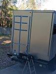

2 bikes 2 brown dogs
Active member
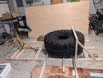
There will be a basket on the bottom that allows the tire to slide between the rear wall and the outer basket. This photo shows a wood mock up of the 'ladder' on the garage floor with the basket capturing the bottom of the ~12" of the tire.
There will be a tension bolt through the center of the wheel to the 'ladder' to snug the tire to the rear wall once it's set in.
I'll then run a ratchet strap over the top of the tire from one side of the basket to the other (driver to center).
At the top there will be a collapsible lifting hook. It will stick out far enough for me to run the rear winch cable up through a pulley and back down to grab the tire.
2 bikes 2 brown dogs
Active member
StenchRV
Well-known member
One thing I can offer on the tire issue is that I underestimated how hard finding a rack solution for a 43.5" would be. When I designed the frame I put some heavy support members on the rear wall and capacity for a lifting point from the roof. I figured I'd find an off the shelfext month it should be installed but basically I'm using stainless 1.5" tubes to make, basically, big ladder on the rear wall. The blue tape is 'close' to its' actual location.View attachment 761350
Funny how my rear wall looks about the same about now, blue tape assisted design
My RAM 5500 will be headed to the dealer for a speedometer calibration, hopefully next week. Waiting on a recall part to come in. There are no speedometer recalibration tools out there yet for the 2022's and above yet, as of a few weeks ago. Mopar has a good lock on the computer. :-( Good news is it is only $150. Called a few name brand tech lines too.
Keep the ideas coming! Looking forward to the updates....and the pictures
CHEERS!!
Craig
2 bikes 2 brown dogs
Active member
My original purpose for adding to this forum was to focus almost entirely on my mistakes, planning or installation, or the benefit of others.
Now that I'm getting into the dirty details, like the hydronic system and distribution panels location, I'm realizing there are a lot of nuances that would be beneficial to share. So if I found my self googling some part for more than two hours or assembled a test run on the garage floor I'm realizing those pre-assembly exercises may be more beneficial than a specific mistake made and a final product so hear goes.
Now that I'm getting into the dirty details, like the hydronic system and distribution panels location, I'm realizing there are a lot of nuances that would be beneficial to share. So if I found my self googling some part for more than two hours or assembled a test run on the garage floor I'm realizing those pre-assembly exercises may be more beneficial than a specific mistake made and a final product so hear goes.
2 bikes 2 brown dogs
Active member
Elwell's Timberline Hydronic
In a previous post about the fuel system I expressed some confusion as to the fuel line sizes. The furnace/boiler/heater Elwell uses is a Planar but I think most companies heater have the same requirements so hopefully this helps more broadly.
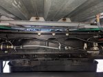
My quandary was that my truck's fuel tank is 5/16" and both the fuel pump and the furnace want to be supplied by a line that has a 1mm ID. Elwell's support got back to me on whether running over sized fuel lines with less reducers was a bad idea and and the answer was 'Bad Idea'. I think the pump needs the greatly restricted pipe ID to pull/push properly so I've made the transitions to the 1mm hose provided in the kit as quickly as possible. The timberline pump is far left and the heater is upstream further 'left'.
As you work your way to the right you'll see how a 3/16" splice acts as a female to female union then transitions to the 1mm opaque hose.
Keep going to the right and you step up twice to the 5/16" needed to tap the factory fitting.
There is another fuel pump furthest right. That isnt related to the Hydronic. It balances fuel levels between the two factory tanks.

2 bikes 2 brown dogs
Active member
Thanks to forum member Victorian on the fuel line sizing as well. I reached out to him in another posting about the issue and he was quick to confirm they've maintained the small line(s) as well.
A few other helpful points. I came across two very thorough manuals on the furnace itself. It took me a minute (hours) to get the chain of command figured out on who's recommendations apply to what model but here's the Family Tree of the furnace as best I can tell.
I only talk about this because it explains why/when the two different manuals may be more helpful. Both are through. Presentation of the wiring diagrams and exploded parts view vary though.
Furnace is made by Advers and it's from their 'Binar' line. My particular model is a Binar-5S compact (i think)
Here's the Advers document:
Autoterm uses that furnace in there product line. Im not sure when Autoterm becomes Elwell but to me they are the same thing.
Elwell sells the product and the whole kit as "Timberline".
Here's the best Autoterm manual I found.
The sales and support team our of Washington are super to work with. I dont mind plugging the company or the individuals here because they deserve it. Kody has been my main contact but there is a long list of folks cc'd in his responses so thanks to all.
2 bikes 2 brown dogs
Active member
On the topic of Timberline support here are a few more helpful points we discussed. I was trying to make more work for myself by uninstalling a pretty decent and compact layout and one of my off the wall options would have put the glycol tank at the same level as one of the air exchangers. It didnt seem like the best idea so I asked for Timberline's blessing or admonishment. Along with that issue I was given a pretty through list of pointers on other installation recommendations. I'll copy paste here. Thanks Kody:
We actually need the heat registers to live beneath the expansion tank. The tank needs to be the highest point in the system to keep air pockets from getting trapped inside the lines and it also allows for the glycol to circulate through the system more efficiently. It works well if the circulation pump is mounted directly under the expansion tank to allow the pump to be flooded at all times and keep cool. The glycol is how the pump keeps itself cool. The plumbing routing should go into the heat registers at the bottom port and out at the top port. The orientation of the heat exchanger isn’t specific, just the routing of the inlet and outlet. Also, on the flat plate water heat exchanger, you want the glycol and the fresh water to flow in opposite directions. This allows for the best heat transfer to the water. The burner should be mounted in a vertical position as well. The top side of the burner is the fuel port/glycol ports.
We actually need the heat registers to live beneath the expansion tank. The tank needs to be the highest point in the system to keep air pockets from getting trapped inside the lines and it also allows for the glycol to circulate through the system more efficiently. It works well if the circulation pump is mounted directly under the expansion tank to allow the pump to be flooded at all times and keep cool. The glycol is how the pump keeps itself cool. The plumbing routing should go into the heat registers at the bottom port and out at the top port. The orientation of the heat exchanger isn’t specific, just the routing of the inlet and outlet. Also, on the flat plate water heat exchanger, you want the glycol and the fresh water to flow in opposite directions. This allows for the best heat transfer to the water. The burner should be mounted in a vertical position as well. The top side of the burner is the fuel port/glycol ports.
2 bikes 2 brown dogs
Active member
2 bikes 2 brown dogs
Active member
One more tidbit on the fuel system. I had a pretty long run from the fuel pump (7' horizontal about 10" vertical). It took about a dozen cycles to get fuel to the burner. I found that the system would engage the fuel pump twice before you got a non combustion error.
The power up process went something like this (it was late so my I appologise if I mis-remember the specifics):
There are three circuits to power up and once the burner is 'asked' for heat you'll hear a fan noise of sorts spooling up in the burner. It takes about a minute for but then you'll hear the fuel pump start clicking at about once per second. With dry fuel lines things go quite for a little bit and then start up again. The fuel pump runs much longer on the second attempt. Then you get an error code.
That second attempt is where you get the most air purging from the lines so wait for that then reboot.
The 1mm line is opaque so once the pumps clicks (pulses) start moving toward the burner you can see the little drops in the line (ants marching). That made it pretty easy to tell when the air was purged. Being dark out with a headlight actually made it a little easier to see the fuel drops than in full light. Or maybe my readers positioned themselves just right
Last thing on fuel. The Advers document spec's that the burner consumes 0.6 liters of diesel per hour.
I reached out to Timberline for a little clarification that thinking that the burner time may be forced to cycle. I'm really just curious. At this point I'm going to presume I'm burning .6/hour and allocate my self 4 gallons a day for heating demand when it's too cold to ski......which is not really a thing.
2 bikes 2 brown dogs
Active member
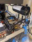
The Timberline wiring harness was exceptionally well labelled. Plug and play would be an understatement.
That said you have a furnace and a fuel pump that live outside everything else lives inside so you're cutting holes somewhere.
Here's how I approached it to minimize penetration diameters:
Starting with the control box inside there are two Molex type plugs that need to exit the habitat and hit the furnace. From the furnace there is one wire run that stays outside and goes to the fuel pump.
There is a second run connector that goes from the furnace harness back inside to the glycol circulation pump.
There is a third 4 Pin AMP connector for "heater data" that goes from the furnace back into the habitiat.
There is a large relay that lives between the two exterior Molex connectors and the interior control box.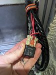

2 bikes 2 brown dogs
Active member
I considered trying to extract pins from the 4 different connector types and push wires and pines only through the floor and quickly aborted. My path forward was this:
Disconnect the Red/White wire from the relay.
Grab the 12 gauge ground (black) wire that bypasses the relay and work towards the control box. In about 8" you'll find where the small gauge black wire from the relay is spliced into the 12ga via a butt splice/connector. One large ground exits the other end of the butt splice and heads to the control box harness.
Cut that ground wire upstream of the butt splice.
Now you can leave the relay inside the habitat. Take the other stuff outside.
You'll be able to plug the two Molex into the furnace.
Then send the 2-pin fuel pump connector to your outside fuel pump.
Now the 2-pin circulation pump is the biggest thing that needs to go back inside. That controlled the hole I drilled.
Attachments
Similar threads
- Replies
- 1
- Views
- 345
- Replies
- 1
- Views
- 1K
- Replies
- 59
- Views
- 23K
- Replies
- 25
- Views
- 19K

