Some North American body mounting info here. http://www.kenworth.com/brochures/T300_Body_Builder_Manual.pdf
You are using an out of date browser. It may not display this or other websites correctly.
You should upgrade or use an alternative browser.
You should upgrade or use an alternative browser.
pivoting frames and mounting campers
- Thread starter lehel1
- Start date
Thanks Mick. The body mounting guide has a good description of the 3 and 4 point pivot mountings in 8.2.
From what I can gather it sounds like the All Terrain Warriors mounting is similar in concept to the mountings in section 9 - spring mounted at a number of points along the frame.
From what I can gather it sounds like the All Terrain Warriors mounting is similar in concept to the mountings in section 9 - spring mounted at a number of points along the frame.
Mickldo
Adventurer
Awesome bunch of links there Mickldo. :victory:
I'm still digesting the body mounting pdf.
I use it all the time for work and I am still trying to digest it all too.
Some North American body mounting info here. http://www.kenworth.com/brochures/T300_Body_Builder_Manual.pdf
Thanks, bookmarked.
Thanks Mick. The body mounting guide has a good description of the 3 and 4 point pivot mountings in 8.2.
From what I can gather it sounds like the All Terrain Warriors mounting is similar in concept to the mountings in section 9 - spring mounted at a number of points along the frame.
I thought you guys might like the 3 and 4 point mounting guide.
Thanks Mick. The body mounting guide has a good description of the 3 and 4 point pivot mountings in 8.2.
From what I can gather it sounds like the All Terrain Warriors mounting is similar in concept to the mountings in section 9 - spring mounted at a number of points along the frame.
I was thinking the same thing. The spring mount seemed clear, the other 'proprietary' mount that looked like it used an airbag or something in place of a spring was not obvious to me. Anyone know what was going on in that instance?
Mickldo
Adventurer
I was thinking the same thing. The spring mount seemed clear, the other 'proprietary' mount that looked like it used an airbag or something in place of a spring was not obvious to me. Anyone know what was going on in that instance?
That looked like a rubber mount to me. Similar to what I was trying to suggest earlier in the thread. Might be good for on road use but probably won't have enough flex for off road.
I saw these interesting Unicat frame flex photos on the blog of Thomas Waas:


German page
Google translated page
That's a lot of flex!
There are also some general build notes on this page:
http://translate.google.com/translate?js=y&prev=_t&hl=en&ie=UTF-8&u=http%3A%2F%2Fauf-achse.info%2FMT_Weltreise_2007%2Fhtml%2Findex.php%3Fsite%3Dunser_mobil&sl=auto&tl=en&history_state0=


German page
Google translated page
That's a lot of flex!
There are also some general build notes on this page:
http://translate.google.com/translate?js=y&prev=_t&hl=en&ie=UTF-8&u=http%3A%2F%2Fauf-achse.info%2FMT_Weltreise_2007%2Fhtml%2Findex.php%3Fsite%3Dunser_mobil&sl=auto&tl=en&history_state0=
Attachments
Last edited:
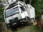
I also see in Thomas' build notes that while his MAN truck is rated for 18 ton GVW, the actual weight is only 12 tons. This provides a safety factor for hard offroad use.
For a 12000 lb GVW Fuso like mine to have an equivalent safety factor, the total weight should be only 8000 lb! For the new FG140, the weight should be a little over 9000 lb.
For a 12000 lb GVW Fuso like mine to have an equivalent safety factor, the total weight should be only 8000 lb! For the new FG140, the weight should be a little over 9000 lb.
Thanks Mick. The body mounting guide has a good description of the 3 and 4 point pivot mountings in 8.2.
From what I can gather it sounds like the All Terrain Warriors mounting is similar in concept to the mountings in section 9 - spring mounted at a number of points along the frame.
I was thinking the same thing. The spring mount seemed clear, the other 'proprietary' mount that looked like it used an airbag or something in place of a spring was not obvious to me. Anyone know what was going on in that instance?
An air bag is basically a spring made out of different materials. They are much better at not transmitting vibrations than steel coil or leaf springs.
Awhile back I did a bit of thinking on mounting and came up with an idea that initially was a combination of air springs and trunnion mount. Later it came to be simplified to a couple strong cross members, each with two air springs and 4 stiff shock absorbers on them. The air springs are mounted as close to the center as reasonable. There would also be a set of stiff shock absorbers close to the center line. These are to dampen the rate of motion between the body and frame. They are not for limiting frame to body twist rate though they will have some effect on that as they are not on the center line. The cross members are to be at the exact same location as the leaf spring mounts thus providing direct load transmission to the suspension. At the front of the body, at the cab, the body is mounted with somewhat hard rubber mounts to have it flex close to the same as the back of the cab. A flexible membrane is used between the cab and back to allow some flex between them and for pass through. It would also be possible to mount the front of the body with air springs and shock absorbers, but that would increase the motion between it and the cab. The mountings would need to be widely spread as they are the side to side stabilizing control for the body. The rear air spring mount provides no stabilization. For failure each air spring is large enough to support at least half the full load. The mounts are designed with three air spring mounting points. One on each side and one in the middle. If an air spring fails, it can be removed, then the other one on that cross member can be deflated and moved to the middle mount location and re-inflated. If all the air springs are deflated the shock absorbers should not support the body, instead bump stops should. The bump stops can be part of the air springs.
Looking at the rest of this thread it would be good if the front frame mounting points load is spread further over the frame. I'm not sure about the rear cross bars. They may stiffen the rear to much. They may need more flexibility between them and the leaf spring mounting points. This is to allow twist into the frame. I can see how to do it by breaking the cross member up into three parts. A bracket at each side that is bolted to the frame with the same bolts that hold the leaf spring mounts, note increasing their size and number may need to be done. The cross bar is then bolted to those brackets, but with hard rubber spacers. This will allow for frame flex. The cross bars could also be top mounted to the frame in a more conventional manner.
The other issue I see with this design is the body now twists and rolls with the front suspension. How is that for handling, etc. Is it bad?
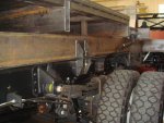
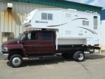
Here is a subframe that I built to mount a big camper on a Top Kick. The top of frame to top of cab measurement on this unit is 5 feet so a 16" elevated subframe had to be built, this leaves 4" cab clearance at the center and the roof of the truck is nicely crowned which keeps the camper contact non existant. The frame is mounted to the chassis in accordance with recognized N/A and manufacturer recommended methods. I don't have any of the test pics but the subframe flexed initially with the truck chassis and then started to separate and open/close within the springs preset travel limits. It drove very good on the highway and some two track dirt roads despite being nearly 13 feet tall, it didn't feel top heavy which was a bit of a surprise to me. If the cab height on the truck was more reasonble the overall height would be substantially less but that's the compromise of buying rather than building.
The rear of the subframe holds a spare tire as well as the hitch structure, with the height required to clear the cab there 4'x8'x8" of storage area directly under the camper and that will flow into the aluminum storage boxes that are being built to fill in the wheel well area of the camper which should finish it up nicely.
The rear of the subframe holds a spare tire as well as the hitch structure, with the height required to clear the cab there 4'x8'x8" of storage area directly under the camper and that will flow into the aluminum storage boxes that are being built to fill in the wheel well area of the camper which should finish it up nicely.
Attachments
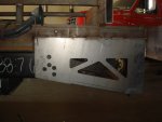
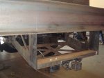
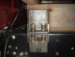
I took a number of pictures of mounting systems at the Mogfest here in Oregon last weekend. I'm going to post them as I have time. Here's the first:


Left side link ----------------- Right side link
This is the mounting system used on a lot of Unimog 404s with flatbeds, including mine originally. There are three mounts on the left frame rail, and three on the right. The right side mounts are all completely rigid. The left side mounts have a connecting bar with a pivot at the top and bottom. This allows for a bit of flex. Since the connecting bars remain approximately vertical, they can still support the vertical forces (though not fore and aft forces). The right side mounts are rigid and constrain the mounted platform in all axes.
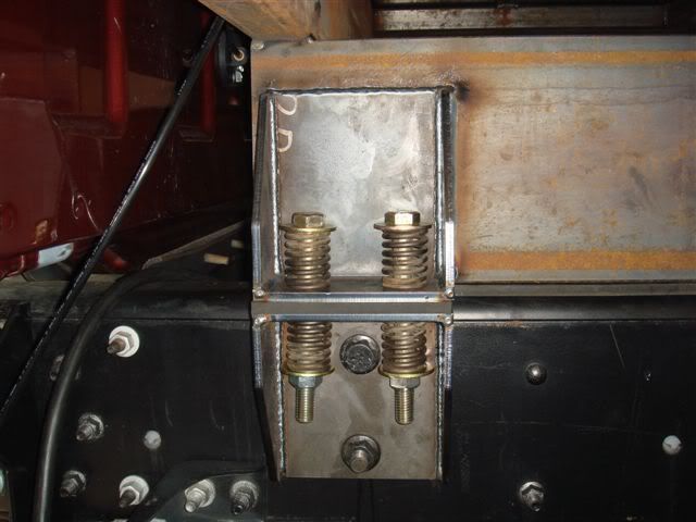
Chip, there are 2 heavy duty shear plates at the rear of the frame and 2 sets of spring mounts per side, spread over a 12 foot frame rail. There is a 3/8" strip of rubber along the entire frame rail for isolation. I wouldn't think you would want any more than a couple of inches of travel allowed by the springs, the shear plates and solid mounting portion of the frame would fatigue over time. It's not a pivoting subframe by no means but a mounting system that spreads the load on the frame evenly which is what most N/A manufacurers specify in thier upfitting guide, which aslo might be a solution for FG's light frame. U bolt/spring combos also work in a similar way and they work well but one nice thing about the mounting brackets we build compared to U bolt mounting is there is no stress on the bottom frame flange so no need to bridge the inside of the frame rail where a U bolt would sit, some manufacturers even recommend a wood block inside the frame rail. To me, wood makes a nice coffee table!
DiploStrat
Expedition Leader
Paging Joaquin Suave
He has recommended using some of these ideas. Seems to me that the advantage is that most of the time, the sub frame will reinforce the chassis and spread the load evenly, rather than concentrating it as can be the side effect of the pivot models. The spring packs should still allow some separation of torque under extreme conditions.
But finally, a slide in truck camper can take SOME torque - the trick is to keep the amount passed lower that the point that the camper or furniture start to become damaged. A typical pickup bed adds some stiffening and I suspect that a properly designed storage body (which is one reason for using this design on an overland truck) could add a lot if all of the box shapes are properly bound together.
N.B. An opinion from someone who has NOT actually owned/built one of these beasts. None the less, following the exploits of the Hackneys and the Smiths (pivot frames) and bggraphix and various (much smaller) Tigers, non-pivot, the conclusions appear reasonable.
Similar threads
- Replies
- 33
- Views
- 4K
- Replies
- 3
- Views
- 1K
- Replies
- 25
- Views
- 5K
- Replies
- 0
- Views
- 554
- Replies
- 37
- Views
- 5K

