Pretty Ugly... 1835, The Build Begins

Madoxen

Active member
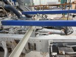
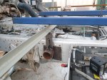
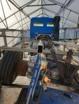
Well after a heap more lifts and some extra steel 75x50x6mm for the longnitudal frames ( to stop the east west flex while it is leant over) we have ended up finding the nutral point of the chassis . We picked up the rear right wheel to 700mm and pulled out the center pivot pin once tipped and then replaced it then the rear pivot pin and then replaced it once we had concluded that pulling the pins made no change to the hole alignment
The observant of u will notice the 100mm pipe in the frame this was just to stop the weight of the frame from pulling the rear end down when pivot was removed but it did freely roll left and right so if there was pressure there it wohld just roll.( i could roll it either way with my little fingure .
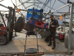
20210704_140421.jpg


20210704_140618.jpg
 
Last edited:

joeblack5

Active member
Fantastic work.

To me the only reason for NOT having a pivot in the front ( not well possible with the tranny in the way anyhow) is that the box can sit lower without interfering with the rear wheel while the frame is twisting. So hence often people make the center or the rear the solid point.

That, pivot front..solid middle..pivot rear, is how my 404 is designed.

Nevertheless I will modify that in the same setup that you have. Solid front..pivot middle...pivot rear. Then I can make a hard connection to the front cab and essential enlarge my living space and stay with a smaller vehicle.

I agree that it seems to be logical that the pivot line in the chassis is in the vertical center between the top and bottom frame rail C beam flange.

But in the unimog 404 it is designed at a much higher vertical position then that.

With that in mind and assuming that Mercedes has done many test and calculations..maybe the pivot is NOT always in the vertical center of the frame rails and maybe even changes depending on the load.

From a complete tension free twist standpoint . Your front hard connection should be theoretical on two individual pivots. On in the vertical center of each frame rail. That might not practical or over complicated but it will help with the east west movement while the frame is twisting for a miniscule amount.

I can not see in your pictures if you have similar rows of holes in the plates that are welded / attached to the frame rails.

Anyhow, great work. Hope to see more pictures.

Johan
 

Madoxen

Active member
I can not see in your pictures if you have similar rows of holes in the plates that are welded / attached to the frame rails.
Hey Johan thanks for the feedback and comments i will post a pic of the front fixed connection for you. But with how the exhast and airbox and fuel tank are going to be i cannot put the fixed point on the center of the chassis but on the top edge of it using oversize steel plate etc.

For the tests i did i welded the angle horizontal bars to a 100x50 spacer and simply clamped this spacer to the top of the chassis. I am now wondering if i should make a moc front fixed pivot and double che k that it does not alter any of the rear pivot points. I sure hope it doesnt lol.
 
Last edited:

joeblack5

Active member
It looks like your cab is not twisted with your subframe that much. Does your can has two connection at the front of the frame rails and one pivot in the rear? In that case the twist that I see is over the frame rails length from the hard connected frame rails to the cab tilting mounts in front.
Is that length and twist conforming to the twist per length you deduced earlier?

what are the vertical dimension of your pivots now relative to the top of the frame rails?

johan
 

Madoxen

Active member
Hi Johan the cab had very little twist/angle compaired to the frame. It is fixed to the chassis in 4 points 2 ruberised bushes with aprings at front which it hinges on when u tip the cab and two sprung locking attachment points at the rear.

The pivot points om my chassis are
Rear = 93 mm from bottom /nearest the ground edge .

Middle = 184mm from bottom

There is a 100mm space between the top edge of chassis and the bottom edge of subframe.

Subframe size is waiting on engineer to give me final calculated size but originally was 150x100x9mm by 5500 long plus the 150x150x9mm out riggers to mount container . This was to enable it to take the full weight of a loaded 20 foot contIner incase i or anyone els decided it would be a good idea to use it comercially. I have since changed this so the truck will be registered as a rv /campavan and not commercial.
 

joeblack5

Active member
Interesting, so the pivot axis runs under an angle thru the frame rails.. that is as in not parallel.
Are you going to repeat your test with a load on the subframe and see if it changes?
Also how do you feel about the localized stress on the frame rails when the subframe and camper pivot from left to right and visa versa?

Johan
 

Madoxen

Active member
Hey yes you are correct that it does not run parellel to the chassis but at an angle.
The way i plan to mount the pivots will spread the loading out somewhat but not the same as an intermediat frame over the chassis but under the subframe.

Yes i do plan to repeat the tests with weight but before i can do that i need to tack up the final subframe and use the pivot points i have at the moment as a more acurate starting point to rerun the test.
 

Madoxen

Active member
I might add to the above comment that the attachment points and the truck chassis have been checked by land transport engineer and oked for the full load capacity of the truck. Which it will never carry as an expedition vehicle
 

Madoxen

Active member
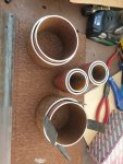
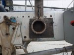
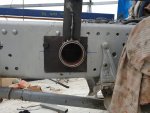
I have found and ordered up the Merc ultra bushes for the middle and rear and the fixed elastomered bearings for the front that uses a 100 OD attachment point. But as i was worrided the center point where i can attach tgis to the front would mess with the test results i already have i decided to make up some test ones out of 100 and 115 od pipe with a good old peice of rubber in the middle

20210709_155730.jpg

Then mounted these onto some scrap plate and bolted it to chassis

20210711_165536.jpg

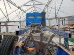
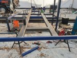
After this i reran the lift tests and removed middle and rear pins neither of which were under any torsional load when rear was lifted over 700 odf the ground with a nice flat mic frame as well

20210715_160729.jpg

The outer 25mmx25mm shs is bent down after the front cross beam but that is not to do with the torsion/ its just bent lol.

The good thing about having rubber in the front fixed bearings is that when twisting the chassis i can see if there is any compression or twist in the front attachment points ( before spot welding to subframe i could twist this and compress/pinch the rubber inbetween the 2 pipes)

Any how i was pretty happy to see minimal pinching if any and this is 3mm of rubber the actual one has nealy 10mm i think.

20210715_160516.jpg

20210715_160559.jpg

I have lots more to report just out of time to post

Stay safe
 
Last edited:

Madoxen

Active member
Been getting a little work done on the sub frame

20210730_155414.jpg

20210730_151604.jpg

Have also recieved a package from Belgium
2 lots of the mb ultra bushes for the rear pivots and the 100mm front fixed point bearings 20210728_100111.jpg
 

joeblack5

Active member
I have found and ordered up the Merc ultra bushes for the middle and rear and the fixed elastomered bearings for the front that uses a 100 OD attachment point. But as i was worrided the center point where i can attach tgis to the front would mess with the test results i already have i decided to make up some test ones out of 100 and 115 od pipe with a good old peice of rubber in the middle

View attachment 672567

Then mounted these onto some scrap plate and bolted it to chassis

View attachment 672568

After this i reran the lift tests and removed middle and rear pins neither of which were under any torsional load when rear was lifted over 700 odf the ground with a nice flat mic frame as well

View attachment 672571

The outer 25mmx25mm shs is bent down after the front cross beam but that is not to do with the torsion/ its just bent lol.

The good thing about having rubber in the front fixed bearings is that when twisting the chassis i can see if there is any compression or twist in the front attachment points ( before spot welding to subframe i could twist this and compress/pinch the rubber inbetween the 2 pipes)

Any how i was pretty happy to see minimal pinching if any and this is 3mm of rubber the actual one has nealy 10mm i think.

View attachment 672569

View attachment 672570

I have lots more to report just out of time to post

Stay safe

I like to your center of frame mount . Looks great.

Johan
 

Forum statistics

Threads
188,367
Messages
2,906,118
Members
230,117
Latest member
greatwhite24
Top