Hey matt,
Great build you have going here. I'm really interested in your battery set up, and still trying to get my head around lifepo4 battery requirements. As I understand it, the battery chargers must be turned off once the required voltage is reached, is that correct? If so, how are you controlling all of the charging sources to do this? Are you charging from an alternator too?
What BMS are you using? is it monitor or management system?
So many questions...but i'll start with those!
Cheers,
Anthony
Thanks Anthony!
Yes, there's a lot to get one's head around on this subject and I'm certainly no expert. I have done many, many hours of research and study trying to understand it. Frankly I still don't get it all but I think some experimentation now will help fill in the gaps.
Anyway, yeah, major aspects of the system that are different from lead acid are protecting the battery from overcharging and stopping charging when the battery is full (i.e., no float charge). Undercharge is a concern too because you can permanently kill a lifepo4 if you discharge it to 0% (whereas a lead acid will be damaged but recoverable).
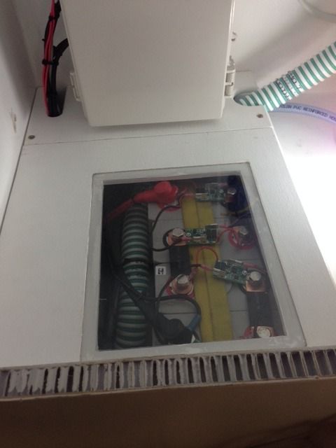
Ultimate protection from over/under charge comes from the BMS. The BMS I'm using is from Clean Power Auto. They focus mainly on electric vehicles but they have a "House Power BMS" that is for house batteries. It is made to work with the sense boards (which they also make) that attach to each cell and thus provides "cell level protection" - that is if any of the four cells hits 3.65v or 2.6v the BMS will drop power to the main solenoid which disconnects
everything except the BMS itself. This is the fail safe protection and should only ever kick in if (1) lots of other stuff goes wrong or (2) one cell is at a significantly different SOC than the others.
Those BMS fail safe protection levels (14.6v and 10.4v) are higher and lower than you ever really want to take the battery though. The BMS has warning level triggers too - 3.6v (14.4v) and 2.9v (11.6). These can be used to trigger an alarm or a solenoid which can disconnect chargers (high voltage trigger) or loads (low voltage trigger). In my case I didn't use them though.
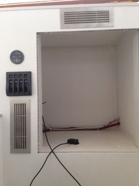
For low voltage protection I am using a Victron Battery Protect. All loads (except the BMS and battery monitor) connect through this. I currently have it set to disconnect at 12.0v. I have the low voltage alarm on the battery monitor (Victron BMV-700) set to buzz at 13.0v - which is about 10% SOC - I shouldn't be going below this level really.
The high voltage protection is complicated, lets see if I can describe it. The Victron Cyrix Li-ct battery combiner protects from overcharging from the alternator. With my "smart" alternator circuit disabled, I'm getting a constant ~14.5v from the alternator - high enough to kill the battery if left unprotected. The Li-ct has a BMS trigger circuit that will disconnect from the alternator when given a signal. I'm using the relay built in to the BMV-700 and have it set to disconnect when the lithium battery gets to 14.1v and re-connect at 13.2v (13.3v may be better). This protection circuit also goes to a regular old 30amp relay that the solar charge goes through. So when the lithium battery gets to 14.1v (95%+ SOC), both the combiner relay and solar relay should open and stop all charging. The battery will drop to it's fully charged resting voltage of around 13.3v. If it starts discharging and gets down to 13.2 volts, the relays will close and either the alternator or solar panels will charge it up again. In effect what this is doing is eliminating "float" charging. I haven't seen anyone use the BMV-700 relay for this and I haven't tested it yet but in theory it looks like a good way to charge correctly with a "dumb" alternator.
I have the solar controller (another Victron piece of kit) set to absorption at 14.2v and float at 13.2v (this essentially disables float charging since bulk charging mode will kick in before the battery gets down to 13.2v). With these settings it should safely work without the BMV-700 relay in the loop. I may pull the 30amp relay at some point since it does draw about 0.4amps when closed.
Anyway, hope that kind of makes sense. As you might be able to tell, I'm having fun geeking out on this but I'm still learning and just starting to test it all out. Some of this may not work as expected! At the very least, I may need to tweak some of the voltage cutoffs as I test things out. I'll surely update as I learn more! Happy to answer any other questions or if someone sees a problem with the logic of this setup, I'm all ears!
matt


