Rango.....1942 Willys MB

Metcalf

Expedition Leader
Thank you. I will try and keep it interesting......

The axles are not going to be anything that special. D30 CJ front and a full float D44 rear.

I agree that a flat fender's are cooler than side by sides, but I have to admit this project is a lot of work and there is not an endless supply of flat fenders anymore. You can buid one from scratch, but doing it for less than 12K would be hard!. ICON has the new cj3b's you can buy....but for like 85K who has that kind of money!

I think flat fenders are cool because they are the original mass produced small 4wd vehicle that started the whole 4wd culture. Here is is 70 years later and some crazy guy is still building something fairly original out of one.

The beauty of the flat fender is the simplistic nature. No complicated electronics. No air bags. No crash test bumpers. No emissions. No heater. No doors. No top. It is simple and raw, pure in its simple function.
 

Metcalf

Expedition Leader
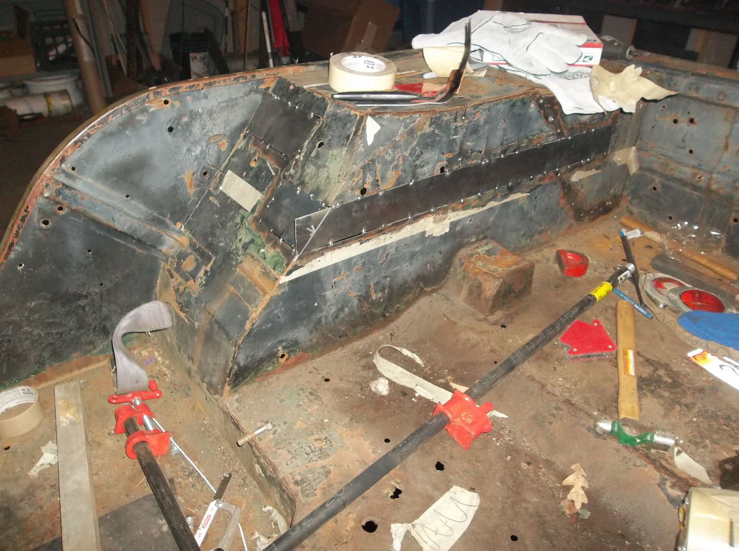
FINALLY! The other rear tub is together!

100_0514.jpg


I still need to do the final welding, but at least all the panels are made and tacked in place. Of course, this one turned out a little cleaner/better than the 1st side. This usually happens when I try something new....1st side is learning, 2nd side goes better.

I need to attack the seams with a wire wheel before I weld them all up. I find using a heavy wire wheel AFTER the seams are tack welded together helps with some final welding.

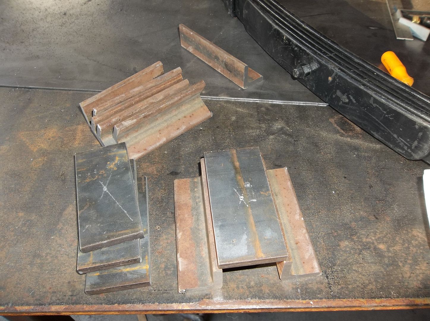
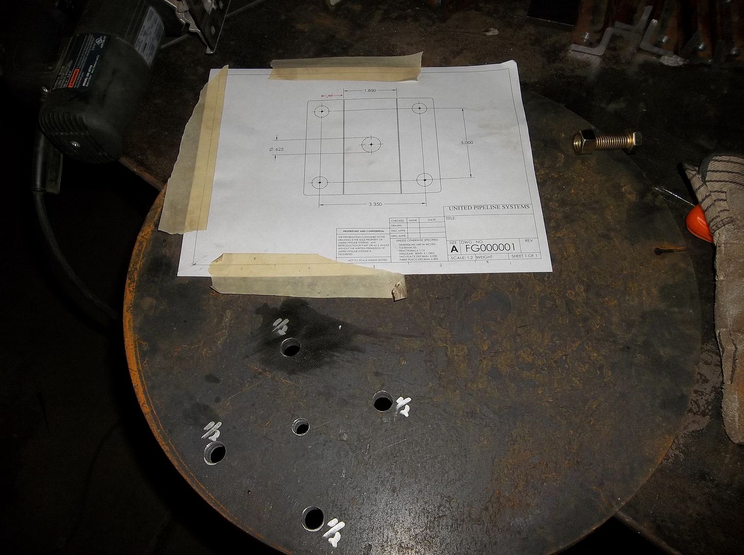
The bandsaw was busy tonight also. I got the final parts cut for the u-bolt plates also. Now I just need to make a few drill templates and a jig to weld everything up. My 4th spring showed up today finally too. My u-bolt order shipped yesterday too! Hopefully I can get the axles under the jeep soon!
 

Metcalf

Expedition Leader
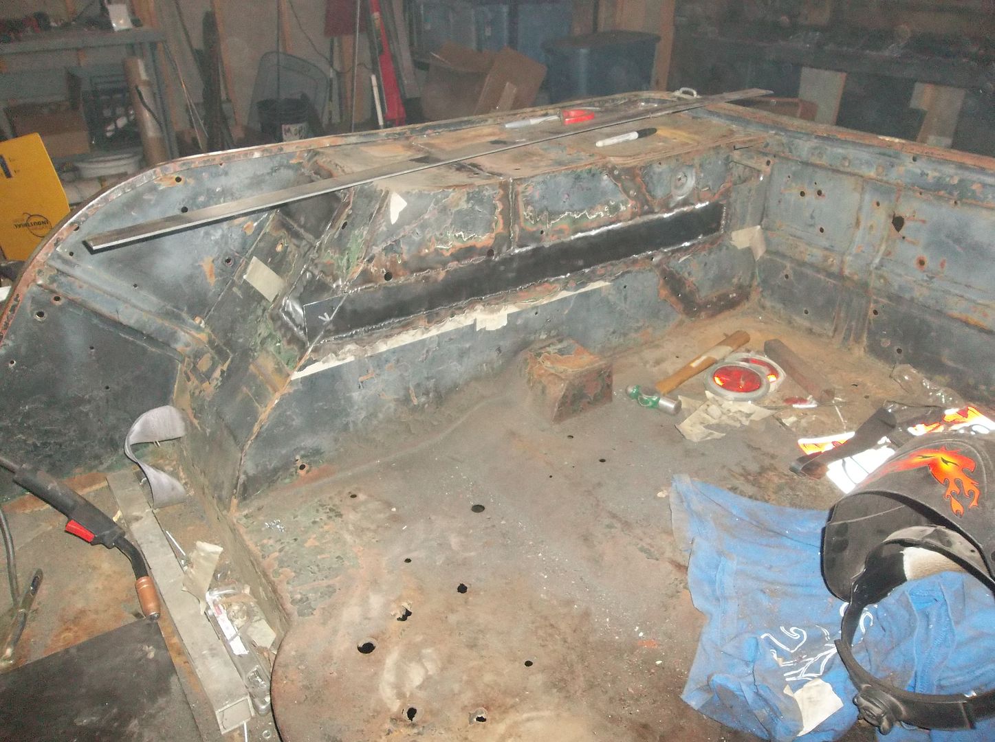
It was a good day....but a long one.

The 2nd tub is welded inside and out. I still have to do a little work in the tool box area on both, but they are not going anywhere!

100_0516.jpg


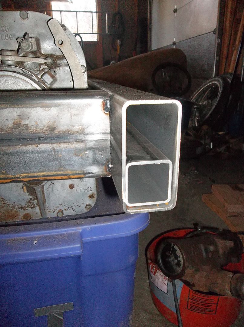
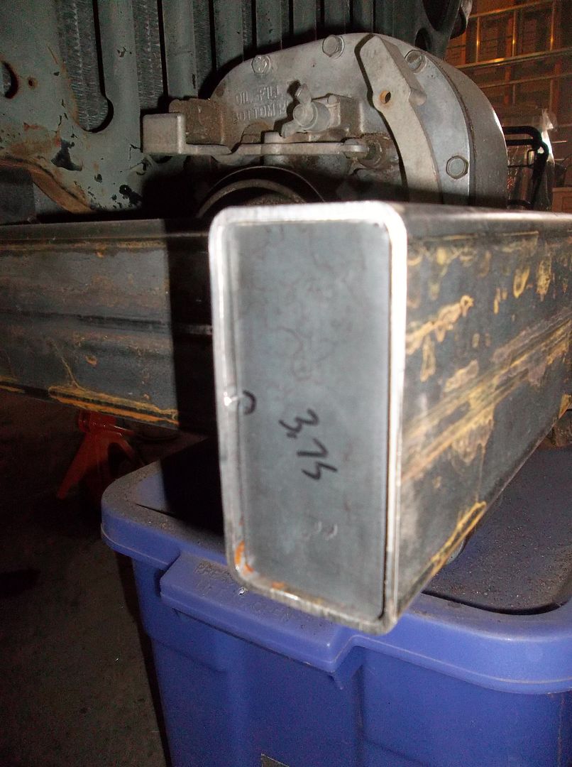
I did a 1.75x1.75, .120 wall sleeve in the bottom of the front bumper. This is to add a little bit more beef with the .120 wall main 2x4 material. I figure the front and bottom of the front bumper will see a fair bit of use over the next 30+ years or so. This should make the front bumper VERY strong, yet fairly light overall.

100_0515.jpg


I also made some end caps for the front bumper. The end caps are recessed to allow an inside weld. I wanted a slightly different look....

100_0518.jpg


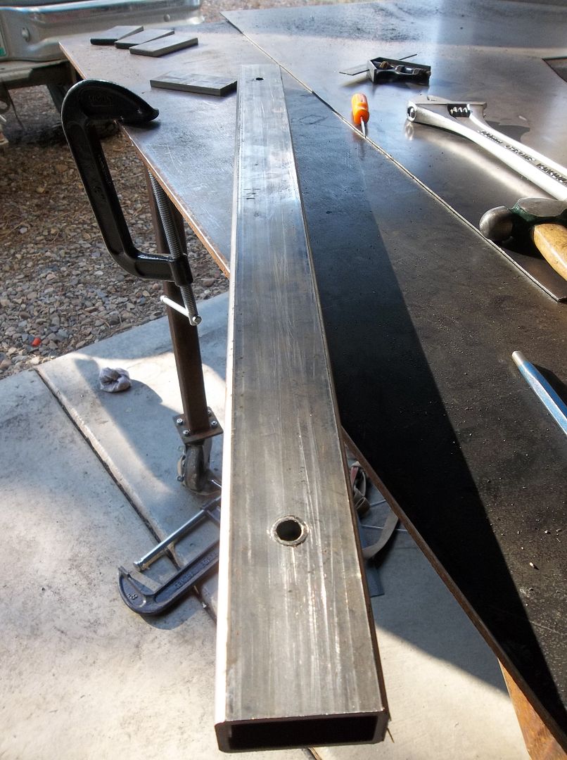
There is another body mount crossmember in the rear tub area that I have needed to make for a bit now. Its just 1x2, .120 wall rectangular tubing with some metal sleeves pressed in for the body mounting bolts....

100_0519.jpg


It goes under the rear floor about a foot from the rear bumper. It is basically inbetween the rear bumper and where the 'machine gun' crossmember is...

100_0520.jpg


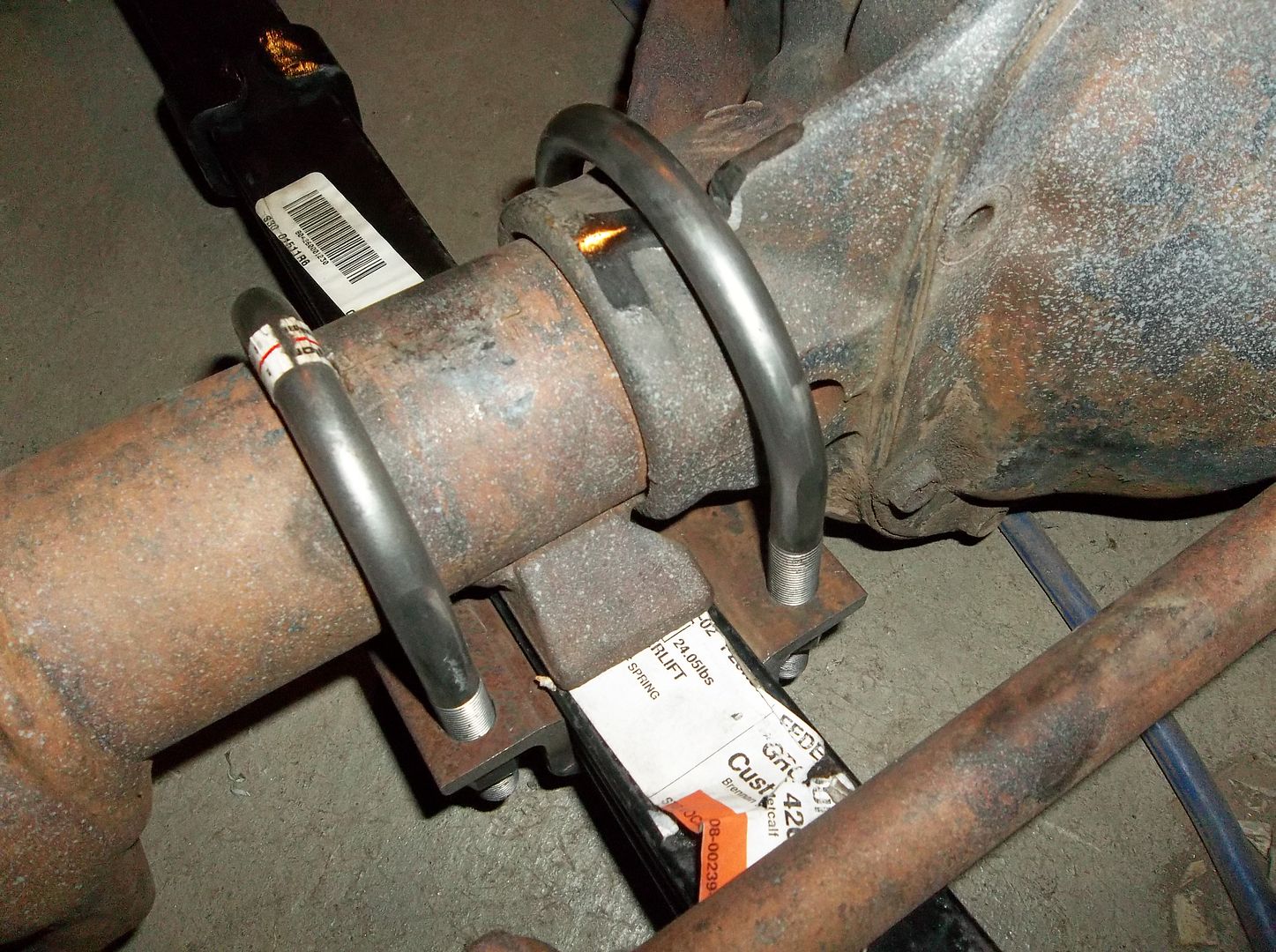
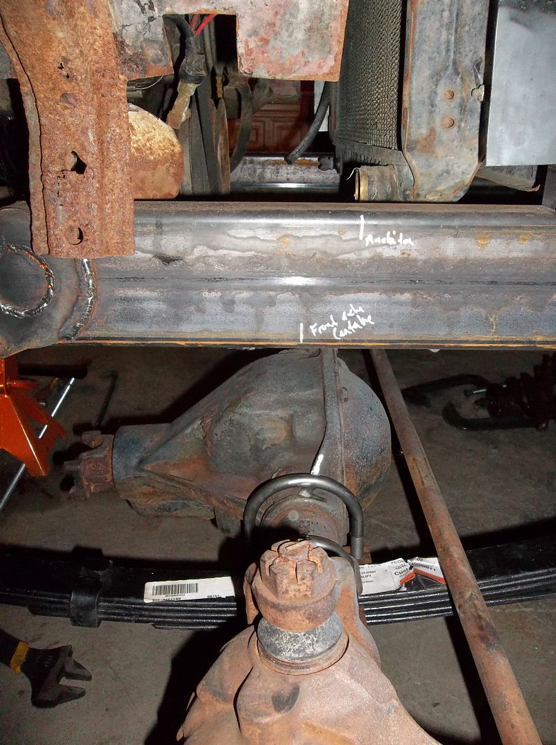
I also finally have all the parts cut for my high clearance u-bolt skidplates. I also ordered custom u-bolts all around a week or so back. This should provide a nice little clearance gain over the old spring plates and THICK military springs. There will not be any u-bolt nuts hanging down to get snagged on anything anymore. Everything other than the diff will be above the bottom of the spring packs....

100_0521.jpg


I also got the old master cylinder, clutch system, and pedal pack removed. I started test fitting the XJ pedal pack. It looks like it is going to work GREAT! It will require just a little bit of modification, but not much really. The top of the pedal assembly needs trimmed off a bit and a bracket added to tie the pedals into the dash area. I'm going to try and make a template for this if I can ever find a factory manual transmission XJ to get some information from....

100_0523.jpg
 

merlin44

New member
It's been a long time since I've seen someone make U-bolt plates like you are doing, but that's the way I've been meaning to make some for mine. You have got a great build going. It's really nice to see someone doing this with old iron, after all of the copycat builds that everyone else does. Not that I mind looking at them, but it seems that the old iron is a little forgotten these days.

Question for you on your spindle adapters. How will you attach the adapter to the housing? Is the ring on the housing 6 bolt and same size? Or will it weld on once installed. I wish I had thought of this before I cut off my housing ends to slide my adapters on.

If you want, I can send you a drawing of my housing ends, and get your opinion. Maybe they may be of some use when you do the next axle.

I tried to come up with a way to do discs on the old (1970?) era 3/4 ton front hub that had the bolt on hubs, so it could use a flanged axle, but the hub OD was too big to fit the 5 x 5.5 wheels. Have you figured a way around this?

Can't wait to see your finished pedal set-up.

Billy
 

Metcalf

Expedition Leader
The spindle adapters just bolt on. The early jeep D44 rear has the 6-bolt pattern on the axle flange. Your standard 6 bolt spindle will just bolt right on to that pattern.....BUT the snout on the back needs to be turned down. I wanted to be able to run identical spindles front and rear AND needed to adjust the width of my rear axle slightly. The adapter I made seemed to solve all these issues.

The willys bearing hub is already 5 on 5.5 and has a 6 bolt pattern for the external hubs. The axles have to have a custom 'flange' on the end for the jeep bolt pattern, but its not a big deal.

Early military models had full floating axles set up like this with a dana 23 rear axle. I just modernized the idea a little bit.

I will try and keep the old iron thing going....or maybe help bring it back!
 

lstzephyr

wanderer
Looking good! Are you going to paint it? Or just leave it green and whatnot?

Have you thought about a soft top? More curious than anything.

IMG_2327.jpg


Looking at that picture of an Icon, I can see why you went through the effort to raise the tubs.
 

Metcalf

Expedition Leader
It will be getting lots of primer and rattle can olive drab. Nothing fancy, just practical for making more modifications in the future.

No full top planned. I may do something custom at some point, but don't really want to mess with it all. I will probably be doing a bikini top of some kind to keep the sun off my head.

Raising the tubs and the tool box redo is going to be worth it, but holy cow was that a pain in the rear!
 

Metcalf

Expedition Leader
Thank you!

Sorry, not too much progress lately. I did most of the drilling for the u-bolt spring plates and I think my u-bolts showed up today. Hopefully tonight I can get the jig for the u-bolt plates done and maybe weld one up for a test fit on the axle!

Getting the axles rolled under the jeep will be nice!

I think I am finally going to order seats next week too!

Still tons to do, just have to keep chipping away at it. I can't wait to have the mock up done so I can tear it down and final weld everything. Then I will need to do stuff like brake lines and the exhaust when I reassemble it before EJS......that doesn't seem THAT far away right now!
 

Metcalf

Expedition Leader
I need a favor. Can someone watching this thread with an XJ, or an XJ owning friend, measure the distance from the floor to the bottom of the brake pedal please?

I am trying to figure out how high I need to mount the pedal package in the tub to get a similar feel to the stock XJ pedal install.

Thanks.
 

Metcalf

Expedition Leader
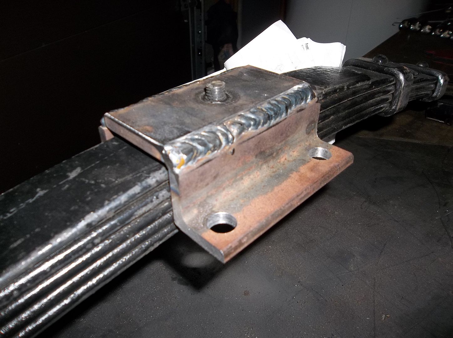
I made some u-bolt spring plates.....

100_0541.jpg


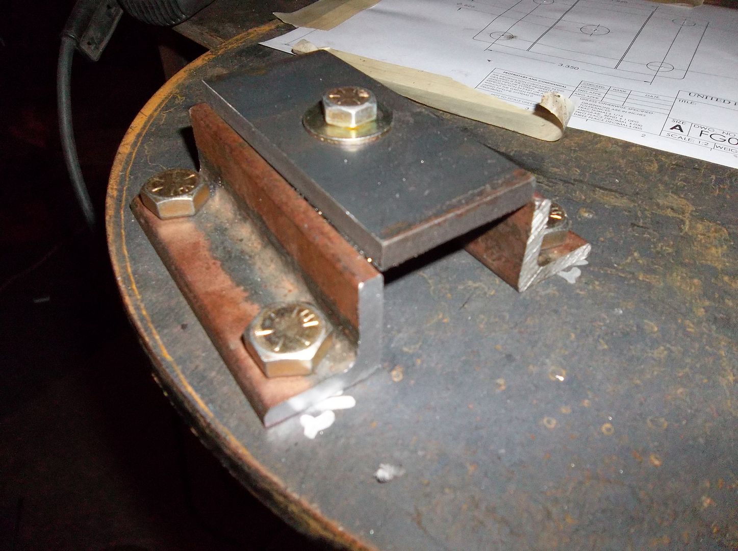
Here is the little jig I made for 3 of the 4 plates I need. I will have to drill another pattern for the odd plate on the differential side in front.

100_0542.jpg


U-bolt plate on the jig. There is a small aluminum puck in the middle that holds the bottom plate at the right height and has a step in it for the 5/8" hole in the bottom. Once you put tension on all the bolts nothing moves. I tacked 4 corners first, then welded two passes on each side. I think it will be enough it won't fall apart for at least a few days.

100_0545.jpg


It fit just great on the spring. There is a little bit of clearance, but only about .060 or so. The springs where not all identical so I didn't want to make them too tight....

The 2nd one is cooling in the garage right now. I let them go back to room temp before pulling off the jig. Now I am off to do the 3rd one. I will probably get the 4th done tomorrow after I drill the other pattern in the jig plate. It runs a larger u-bolt on one end.
 

Metcalf

Expedition Leader
Not much of an update, but an update....

100_0557.jpg


I got the 4th u-bolt plate done, the odd one. I used a 3.5" u-bolt for the 'wide' side. It worked out fairly well. I ended up having to trim one of the webs on the center section down just a bit to fit. I have been contemplating welding a 3.5" radius shim under the u-bolt in the diff to get it to seat better?

100_0562.jpg


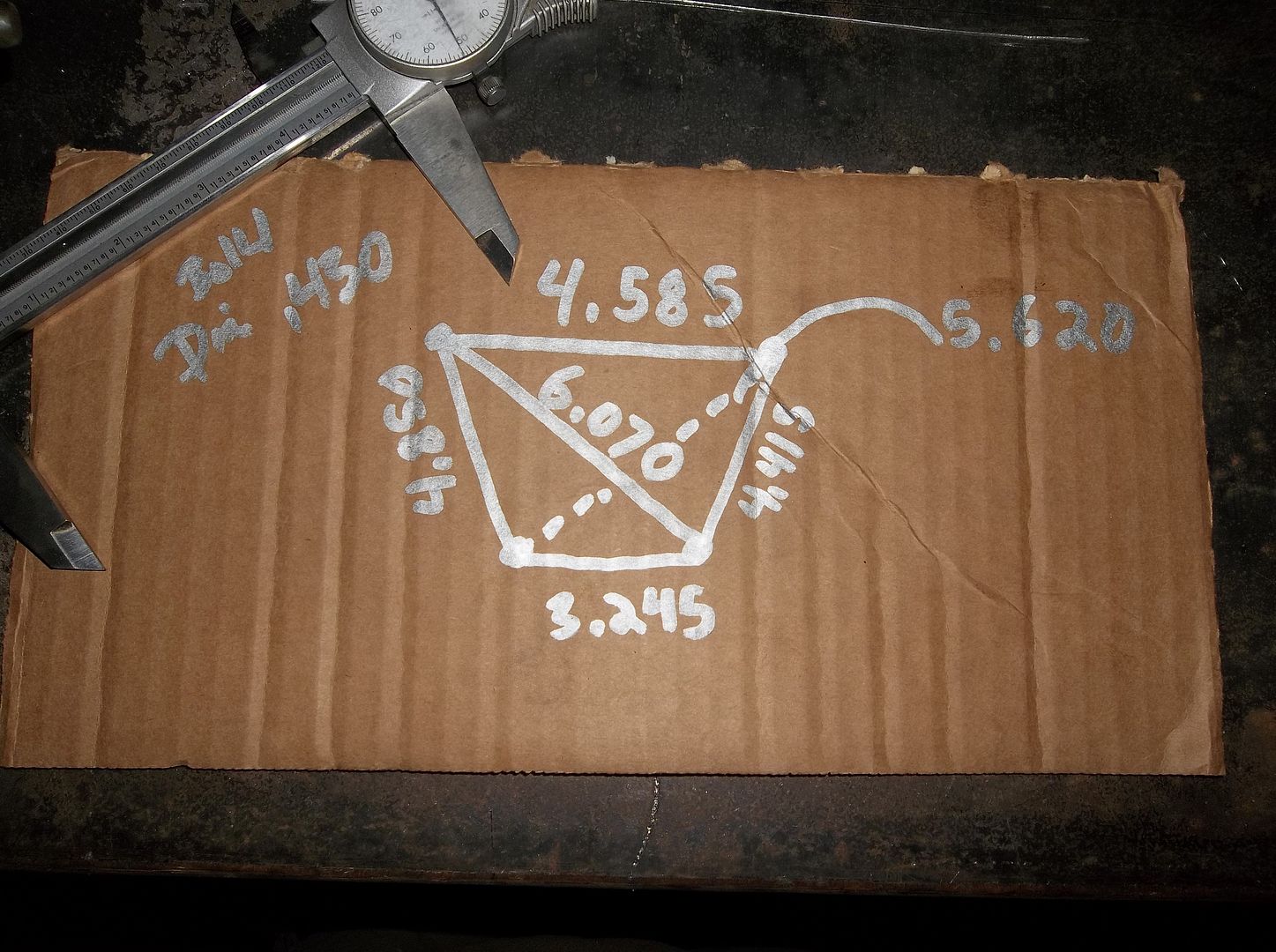
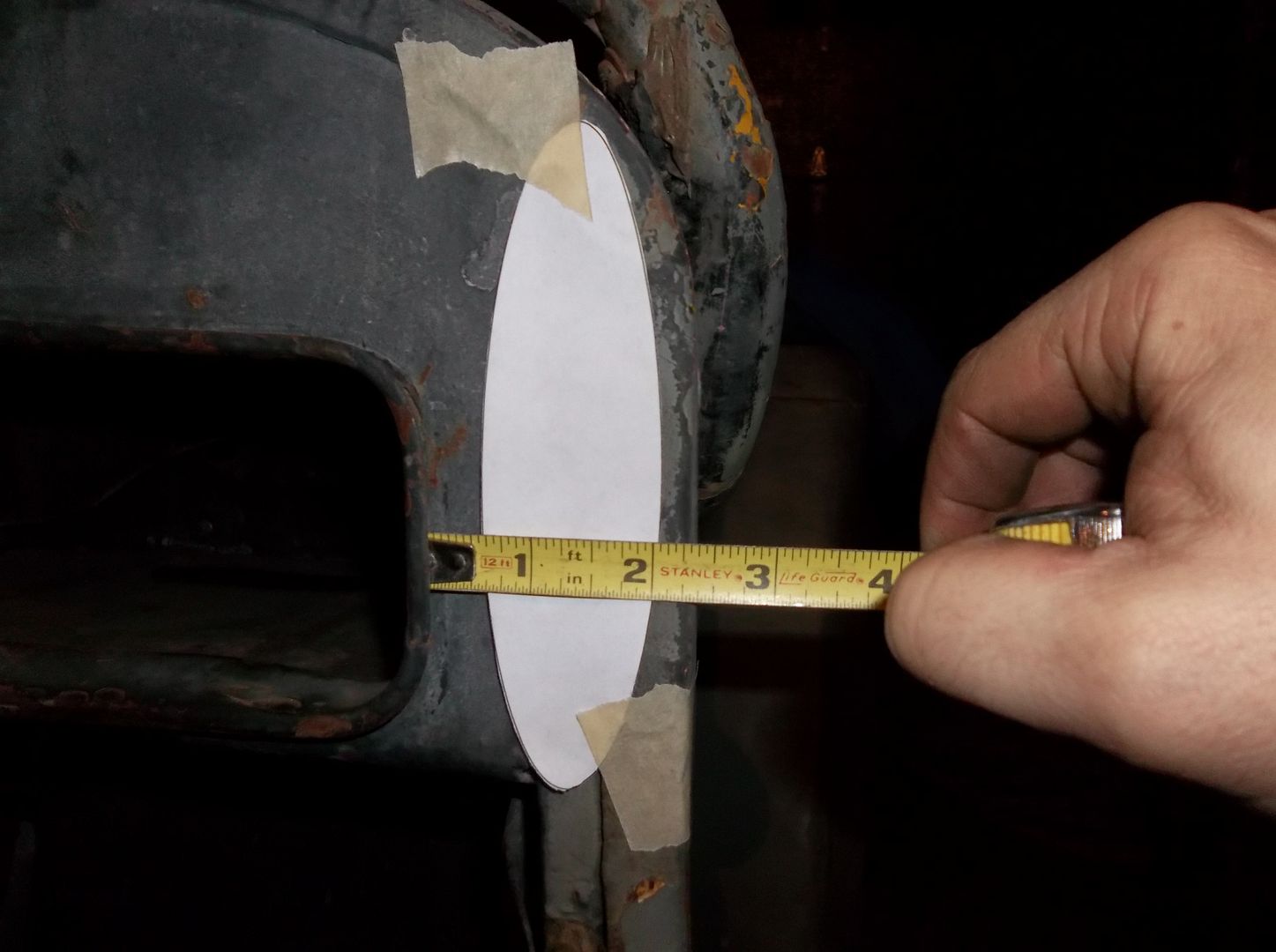
I also measured up the bolt pattern for the steering box. I'm pretty sure the bolts are 7/16-14 (?). I am going to transfer this pattern over to the computer and make a print out template. I think that will help people.

NOTE! These measurements are from the OUTSIDE to OUTSIDE on a .430 dia bolt. NOT center to center!

100_0567.jpg


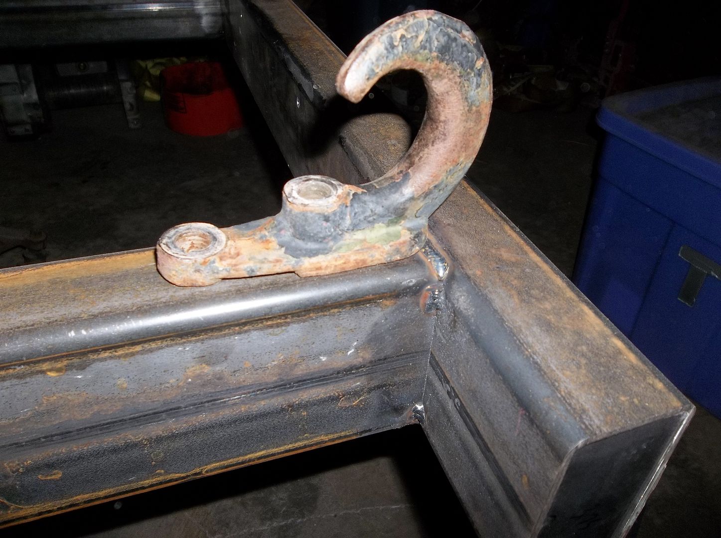
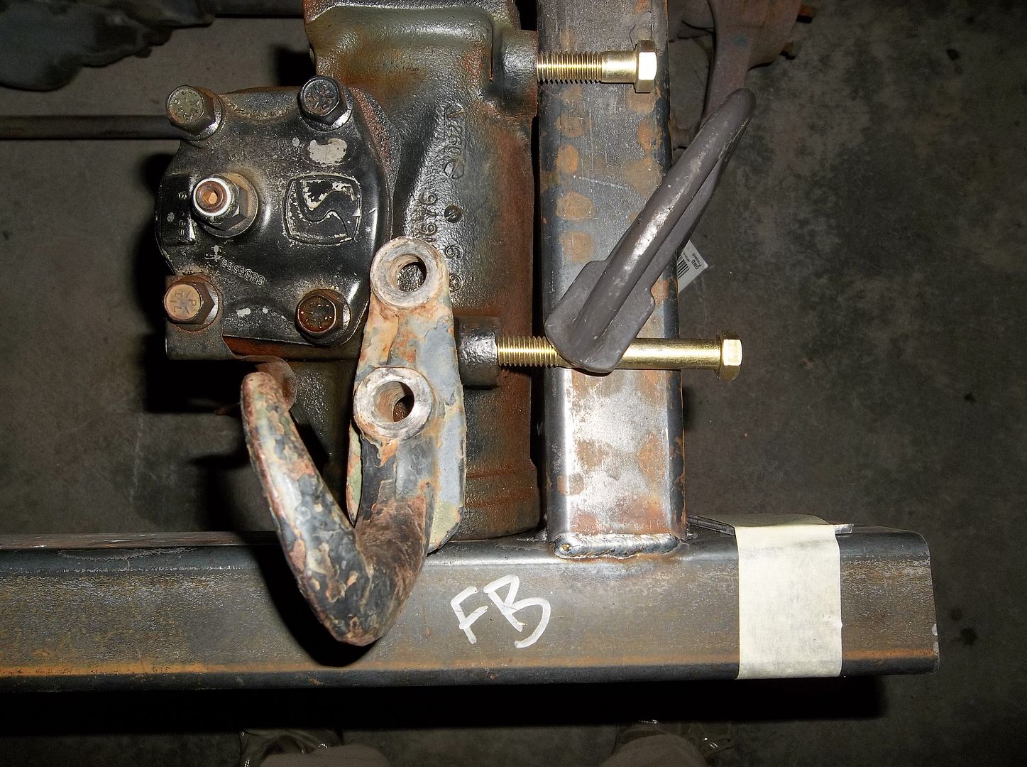
I need to figure out a way to make a way to mount these original USMC tow hooks in the front frame rails. I think I can still slip in a tapped plate or something from the open 'kick' in the frame before I cap it off.

100_0580.jpg


100_0582.jpg


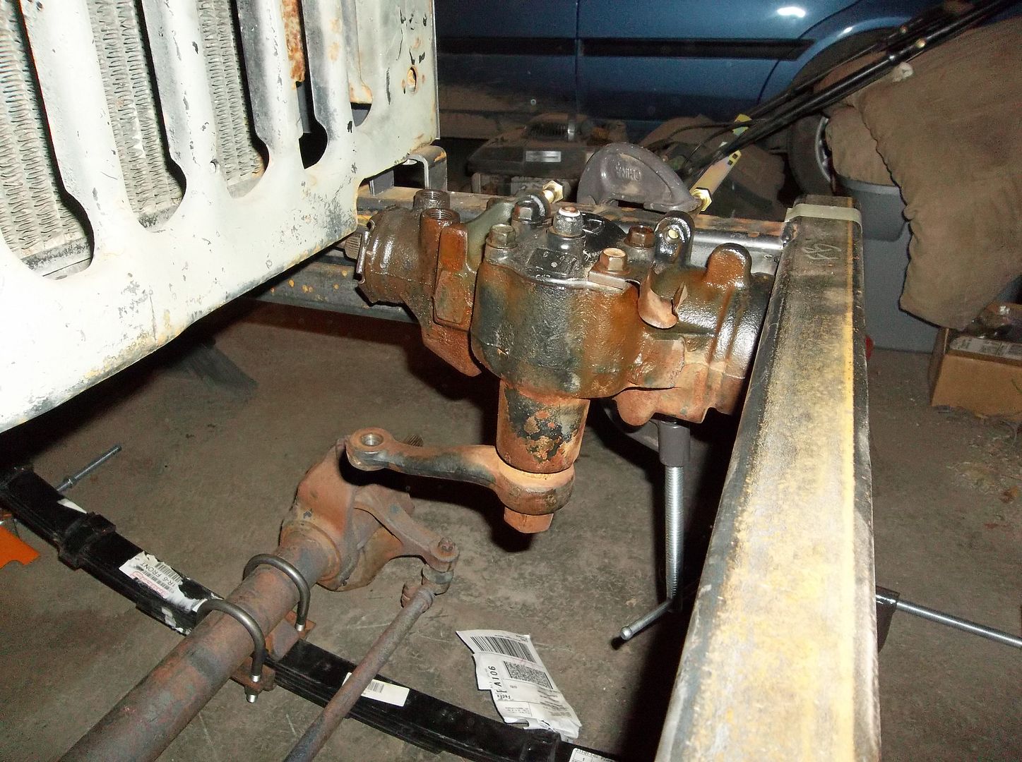
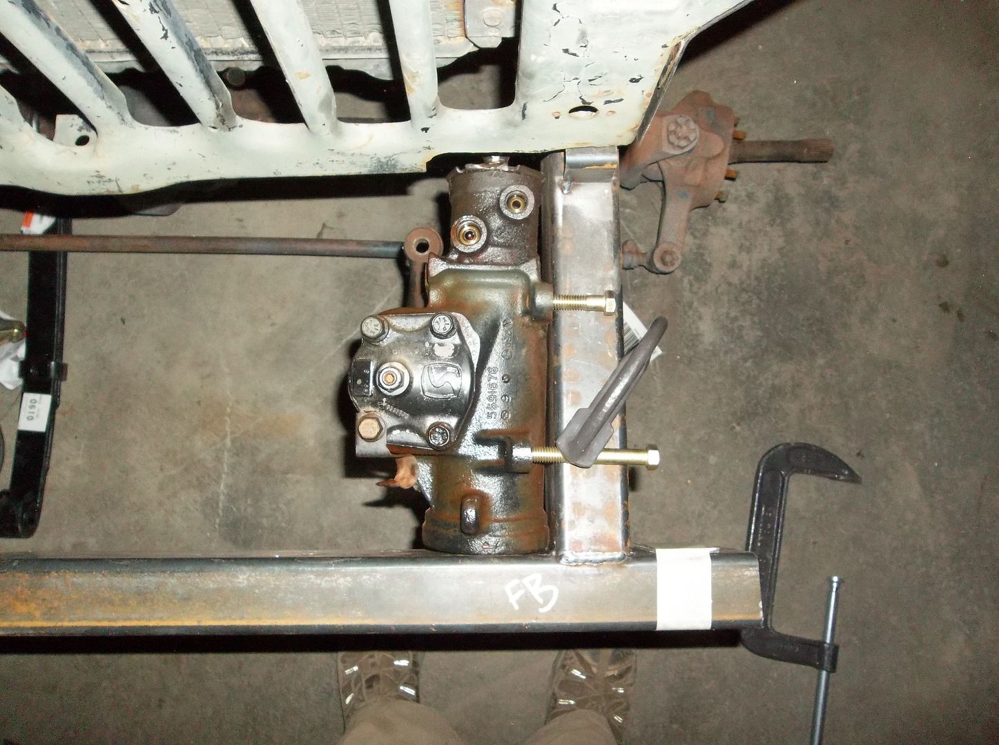
I then clamped the steering box to the frame with some long bolts just to see where stuff might end up. This 'stretched' front frame isn't THAT stretched! The box is still a fairly tight fit I think....

100_0584.jpg


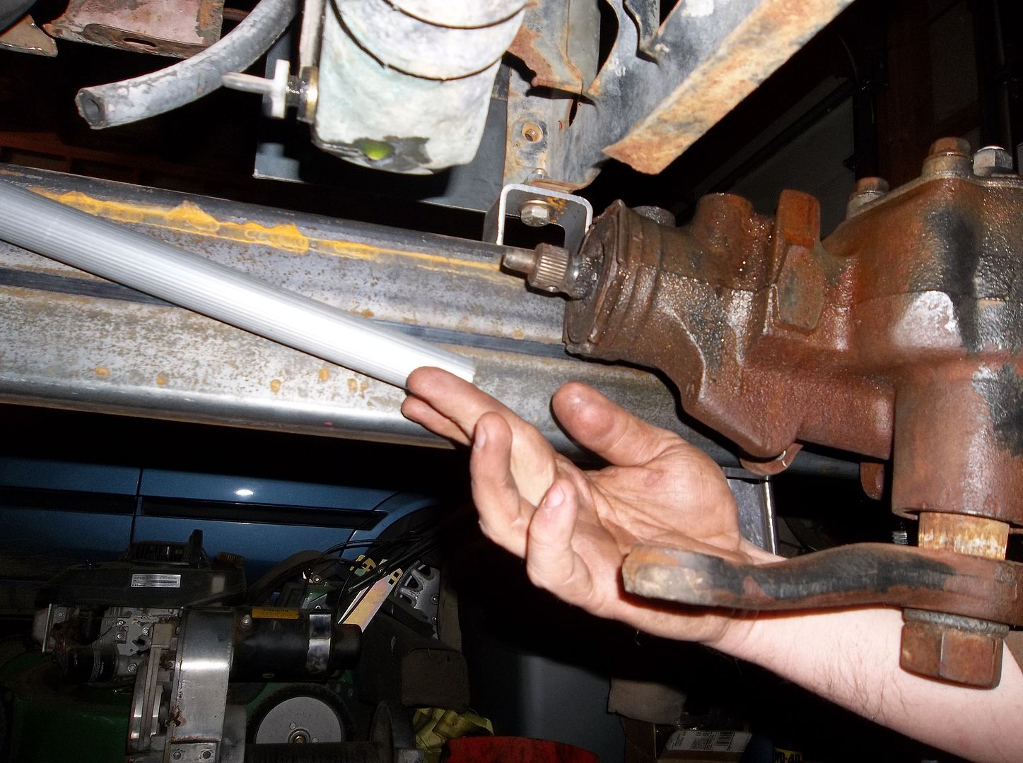
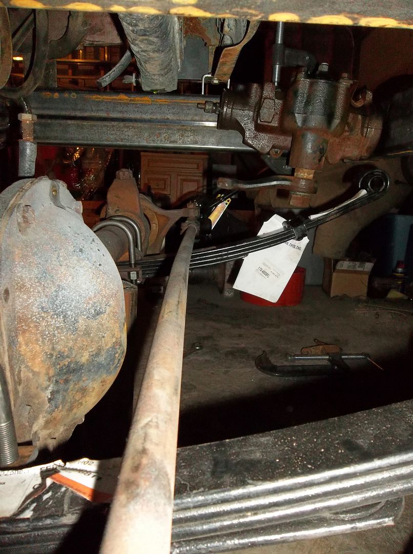
I ran a high tech broom stick steering shaft simulator down from the hole in the firewall. This is how close I get from a straight shot from the steering column hole at the firewall to the steering box. It hits on the exhaust manifold. With the real steering column being more angled and longer this problem should go away. I'm still not sure what I am going to do for the steering column. I feel with the lowered seats the column angle is going to need to be a lot flatter? I have some room to work with, but not much!

100_0565.jpg


The front axle is just about ready to go in for mock up! I was pretty impressed that even with the weight of the tub,engine, transmission, and transfer case the jig rod and spreader still just came right out of the front spring hangers without any binding!
 

Metcalf

Expedition Leader
Fun few hours in the garage.....

100_0597.jpg


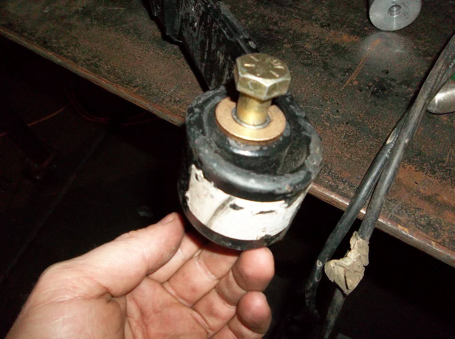
I went old school! I assembled some oilite brass bushings for the springs. They are off the shelf McMaster bushings, 7/8" od, 5/8" id, flanged, and 3/4" long. They worked just perfect, a light press fit. For the inner sleeve I used some seamless tubing that was .625 OD/.509 ID ( .058 wall ). I had to run a .625 drill bit backwards through the assembled bushings in the springs to get the sleeves to be a light press fit. A 1/2 bolt drops right though the sleeve. The bushings where about $1.50 each I think. I will try and remember to get a part number. When I do the final assembly I will cross drill the sleeve for a grease port. I need to get some bolts that are the correct length and drill and tap the ends for a zerk fitting.....

100_0598.jpg


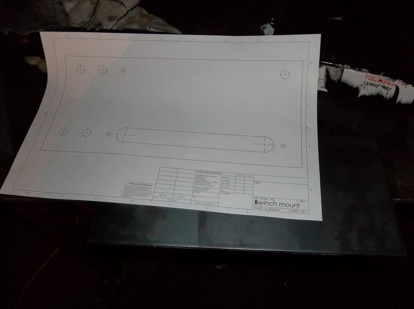
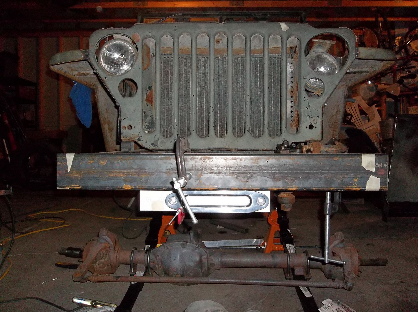
I started building my winch mount. The bumper was pre-drilled for an 8274 mount. The vintage Belleview I ended up with has a different mounting pattern so I had to add a 8th location hole in the plate that will be hidden once its welded in place.

100_0607.jpg


Quick mock up of the position of the plate on the front bumper. The plate is .25" thick. The bumper is 1/8" thick and then in the bottom half is sleeved with another 1/8" tube. I will be 'wrapping' the bumper onto the frame rail with some 1.5" wide 1/8" flat bar on the top and front. The shackle hanger on the bottom is going to tie the bumper to the frame with more material also.

I think that old winch is going to look pretty sweet sunken in the front frame!

100_0606.jpg


This is a slight issue. The tow hook needs to span the forward top mounting bolt for the steering box. I will probably have to sink that sleeve into the frame so it is level on the top.

I still need some ideas on how to attach the tow hooks to the frame? Its not really thick enough to tap.

100_0610.jpg


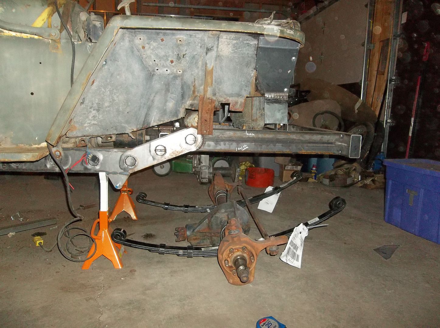
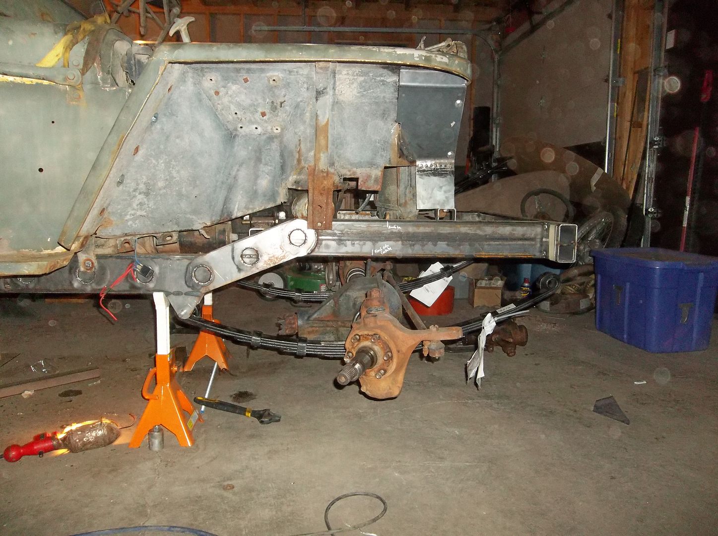
I got the front springs and axle into the spring mounts. That was fun by myself. I glad its not a Dana 60! :D Boy its nice to have an axle in there! I can't wait to put some weight on the springs to see where everything is going to end up! I'm very interested to see what these 1" rear springs end up giving for 'lift' in the front?

100_0615.jpg


The pitman arm looks like it is just going to clear under hard compression. As long as it clears when the springs are flat it only gets better if they go negative a bit...haha.

100_0613.jpg


It looks like my math was pretty close on the axle location. It looks like it will be slightly forward from the location I calculated using the old stock rear springs. A touch extra wheelbase ( 1/2" or less ) will be just fine....
 

Metcalf

Expedition Leader
I have also started thinking more about the details on the cage. This is what a 1.5" tube end looks like cut at a 16 degree angle to match the windshield.

100_0604.jpg


I can JUST squeeze it onto the dash next to the factory glove box opening. In this position I would have to remove the factory pivot arms for the windshield tip out and build something new.

The basic idea is to plate bolt sides of the dash and have the A-pillar dead into the dash and then continue from the back of the dash to the floor. This should allow the most leg room and door space. The down tube would be in basically inside the factory cowl support structure on each side.

Anyone have any thoughts or ideas on cage stuff?
 

Forum statistics

Threads
188,218
Messages
2,903,956
Members
229,805
Latest member
Chonker LMTV
Top