You are using an out of date browser. It may not display this or other websites correctly.
You should upgrade or use an alternative browser.
You should upgrade or use an alternative browser.
Rango.....1942 Willys MB
- Thread starter Metcalf
- Start date
Metcalf
Expedition Leader
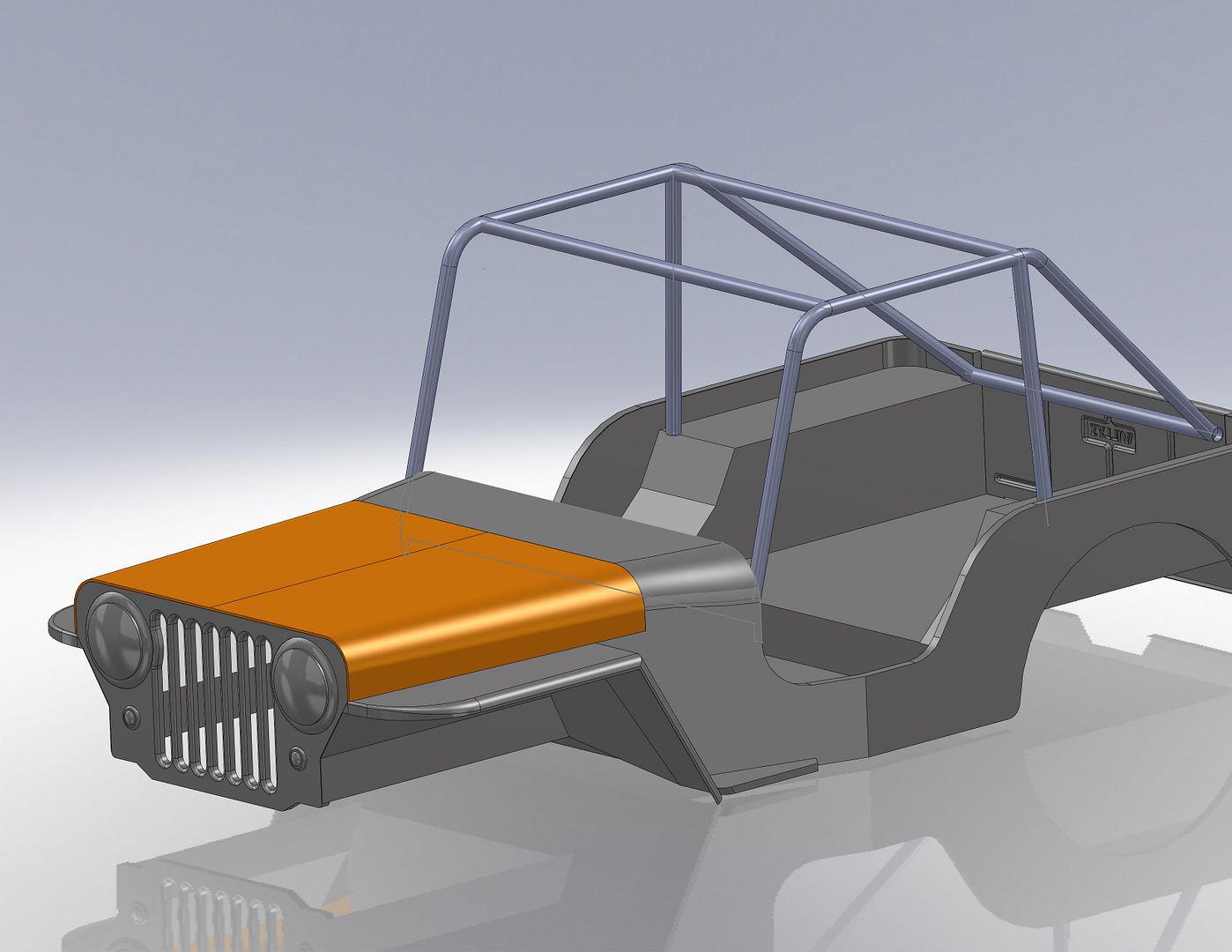
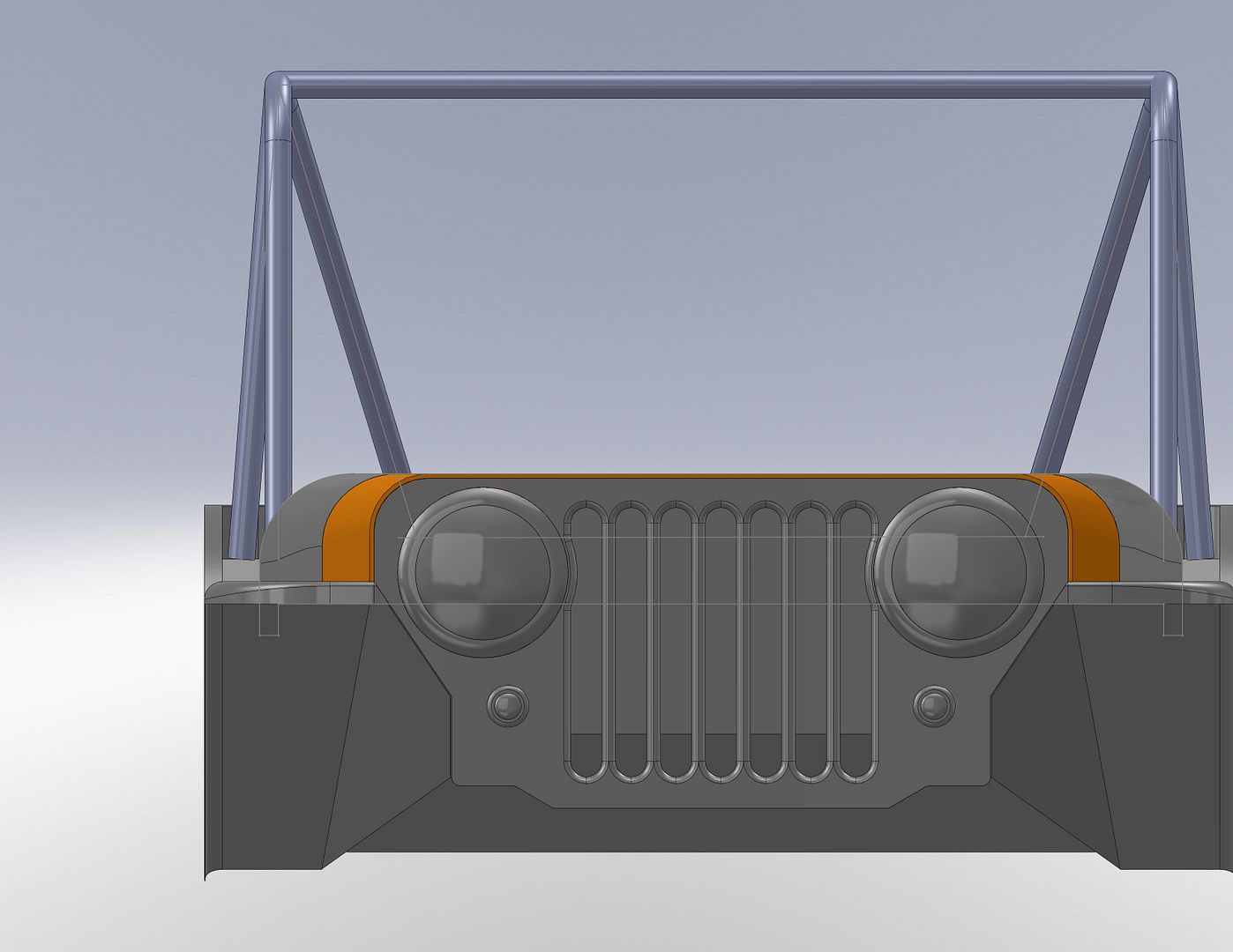
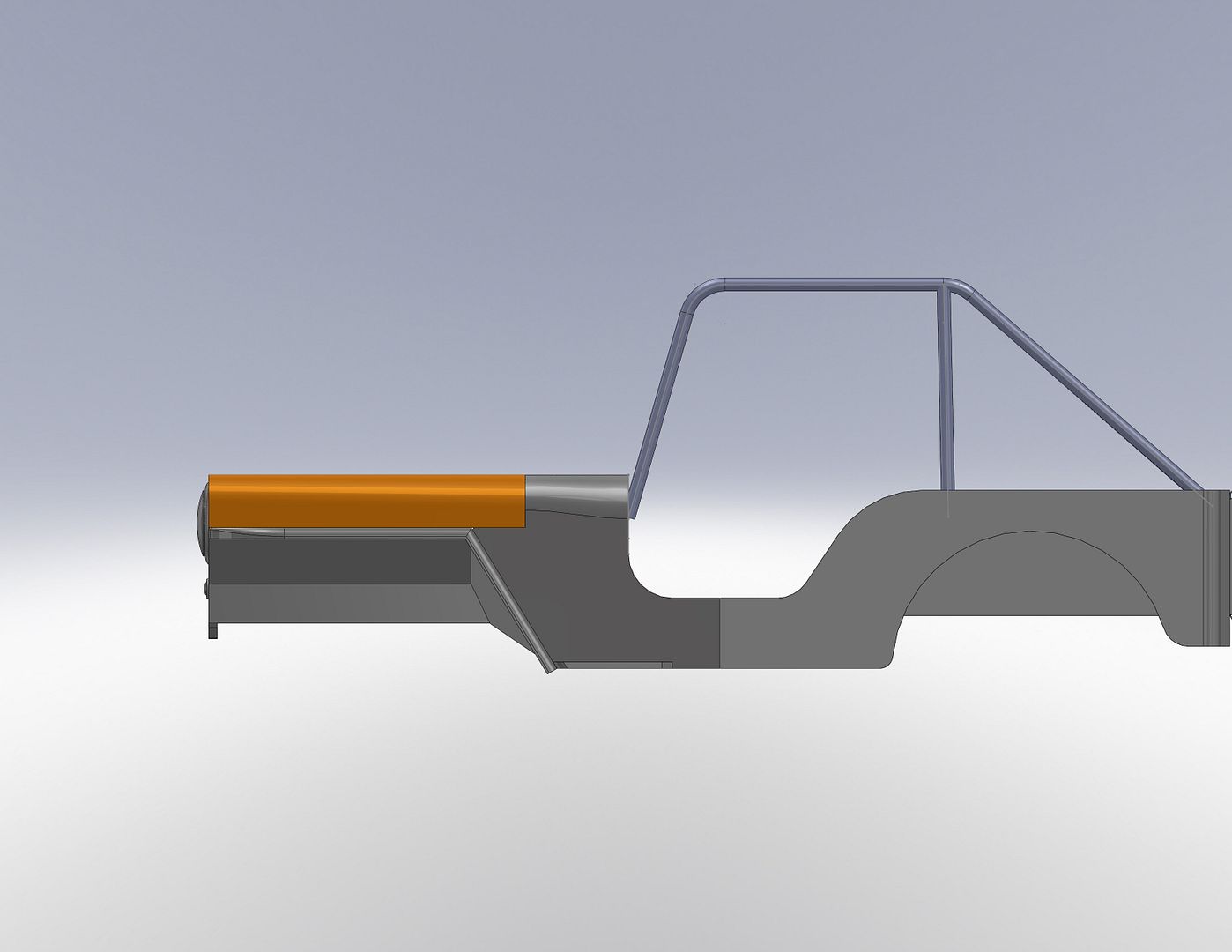
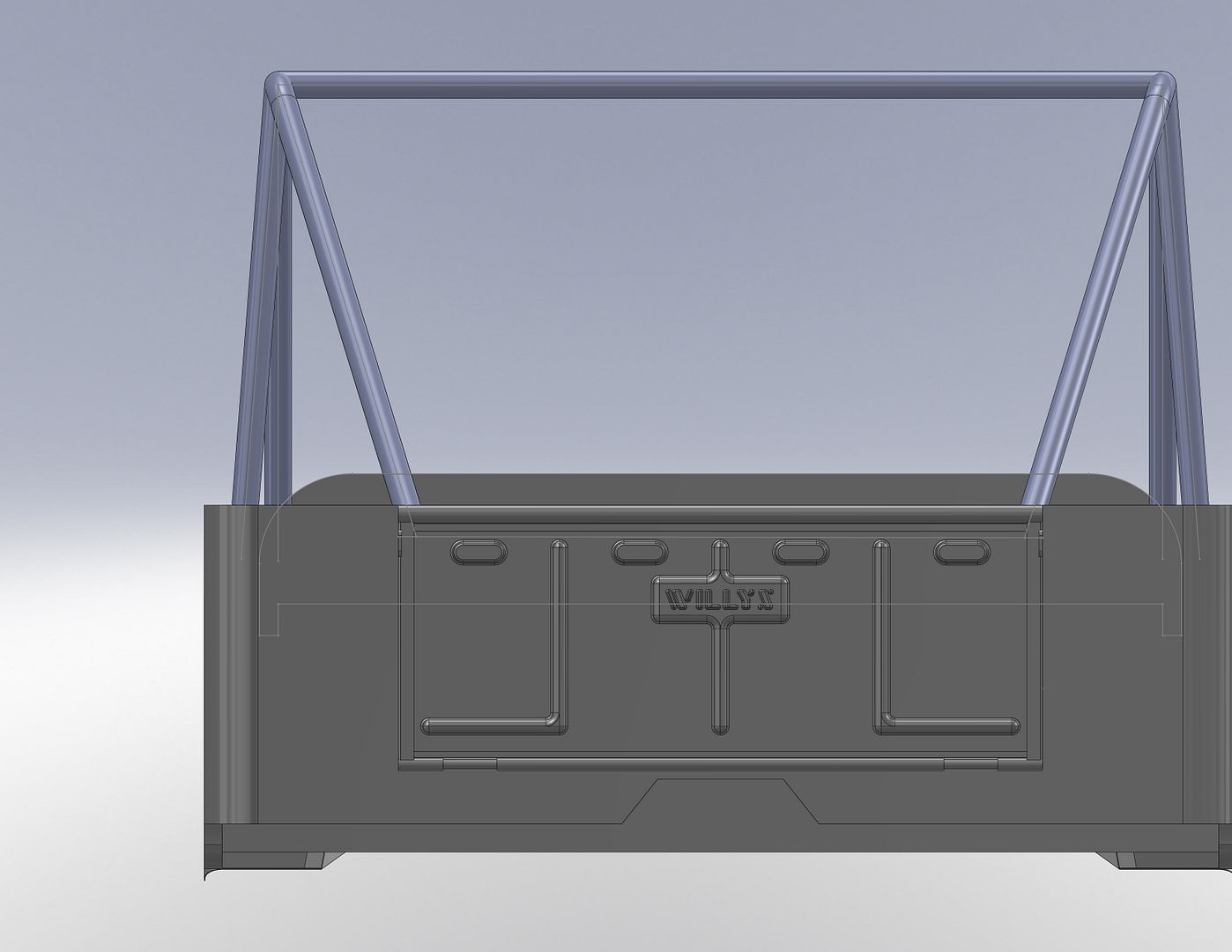
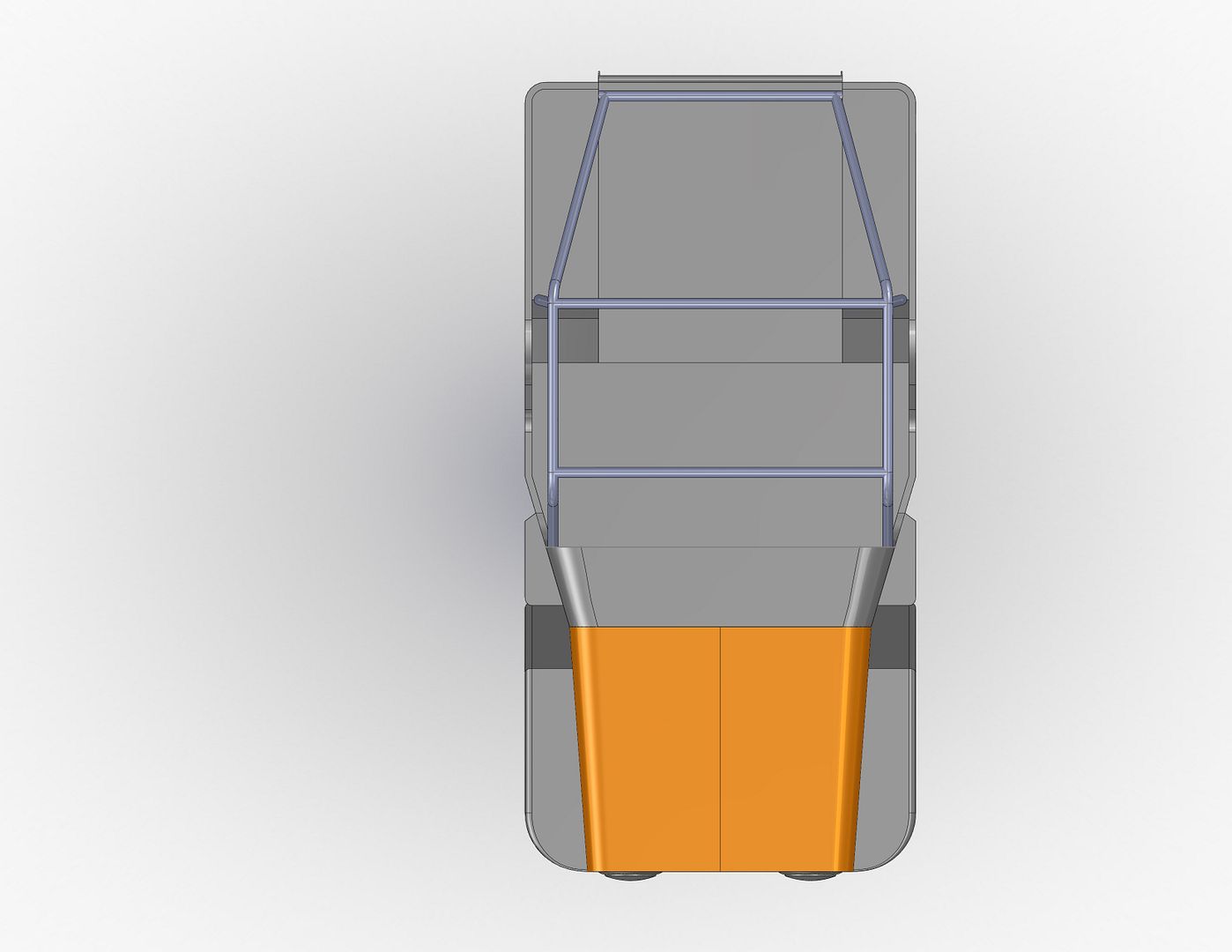
Looking at this chop I did while I was conceptualizing the entire project....
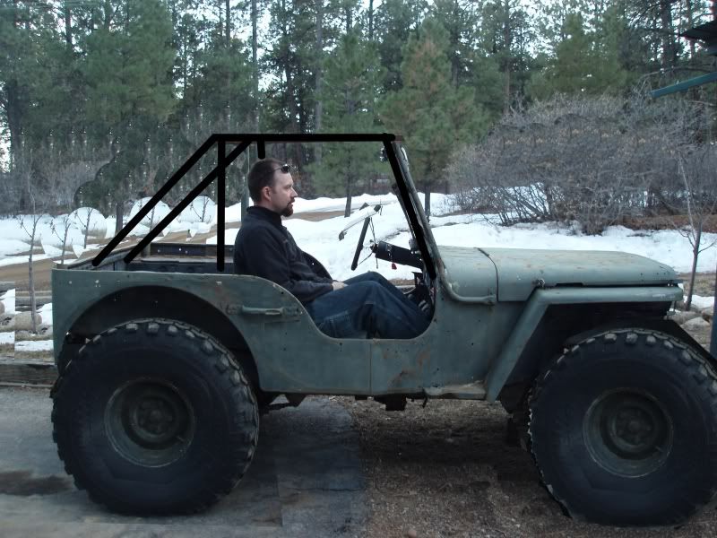
I think the b-pillar of the cage will need to be fairly far back. I am going to wait to finalize the cage dimensions until I get seats mounted....or at least the drivers seat. I need to take some more measurements of the tub also, the model I am working with is a little off compared to my highlined MB tub.
The A-pillar design is still up in the air. I need to think up a simple way to tie it into the dash to save some room. This thing is going to be much more compact top to bottom than most flat fenders....
Metcalf
Expedition Leader
This is pretty boring....but some decent little tricks....
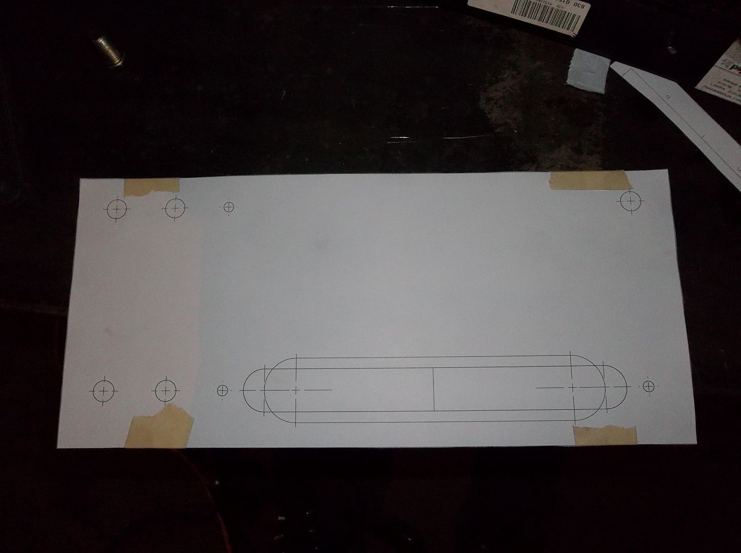
I love these paper templates. All the holes have cross hairs for center punching. I had to make a slightly different template for an adjustment on the slot for the hawse.
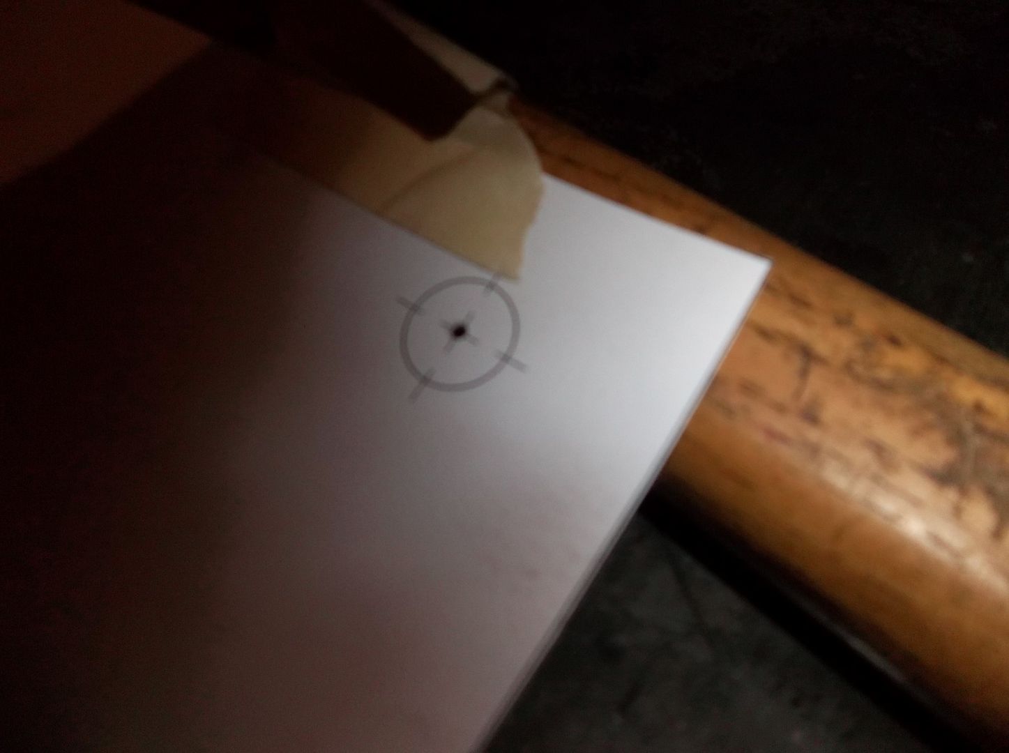
This is what the hole location cross hairs look like after punching. For me this work REALLY well. If you take a little time center punching the location it seems to be VERY accurate.
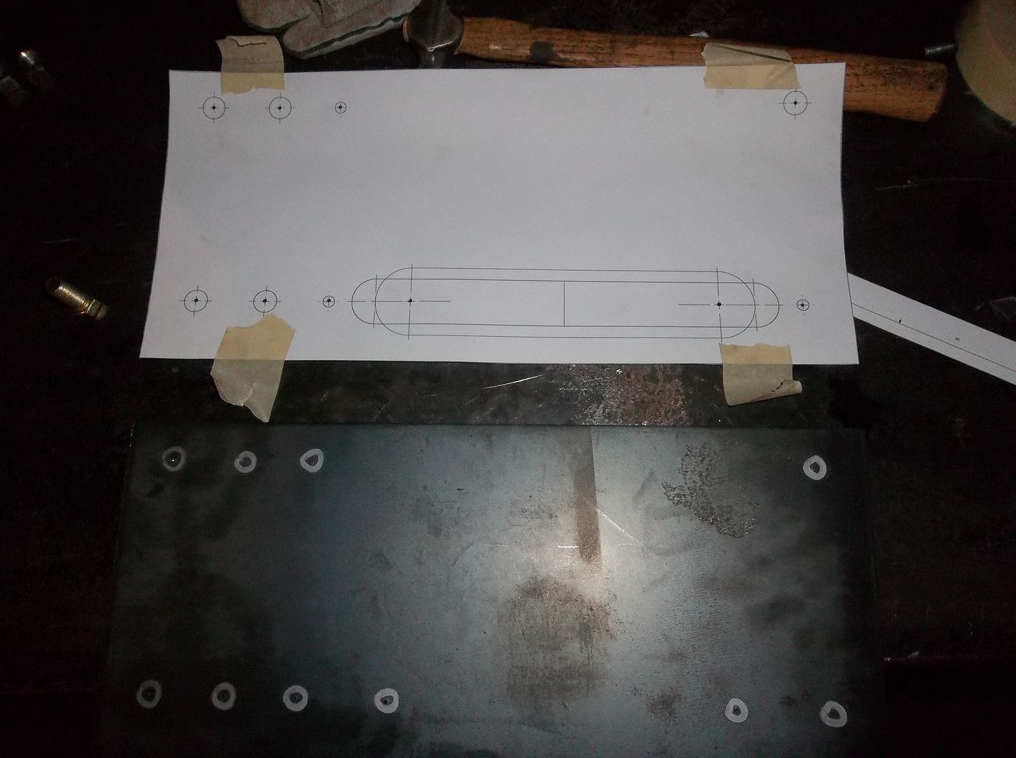
After I pull the template I try and mark the center punch locations with a sharpie so I can find them easier. Note: make sure you punch all the holes you need before you pull the template off. Once its pulled you can't really go back that easily. If its a complex part you can spray glue the template to the metal and wire brush what is left when your done.
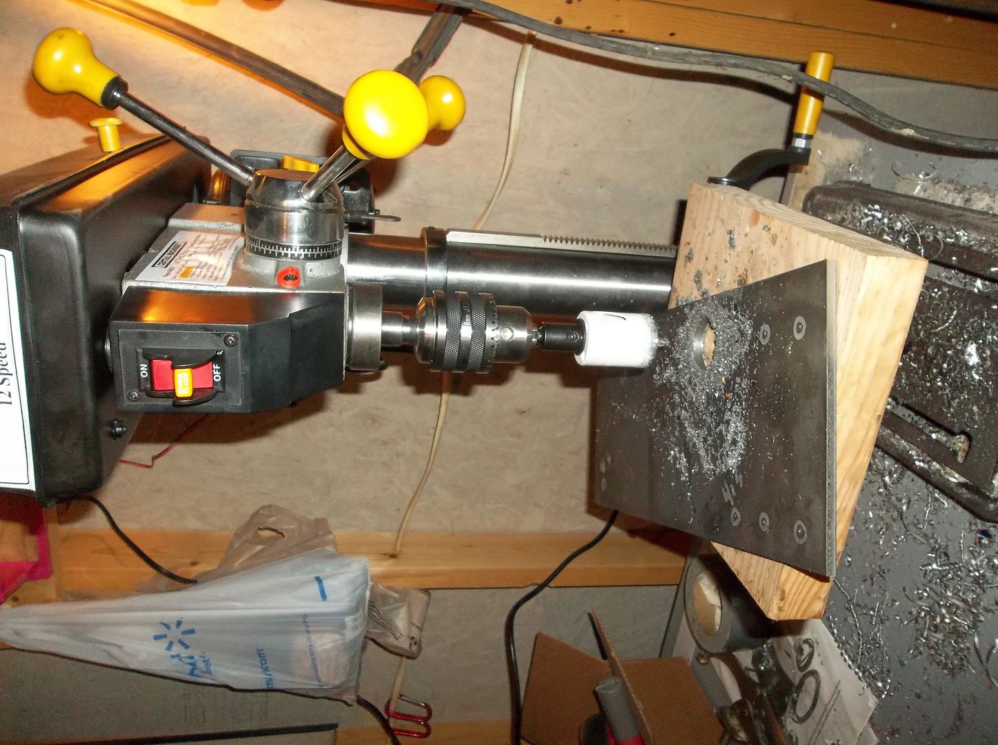
My monster drill press running the 1.5" hole saw for the hawse slot. It did ok with lots of lube. This is the 12 speed version so it goes pretty slow for holes saws....not bad for about $130!
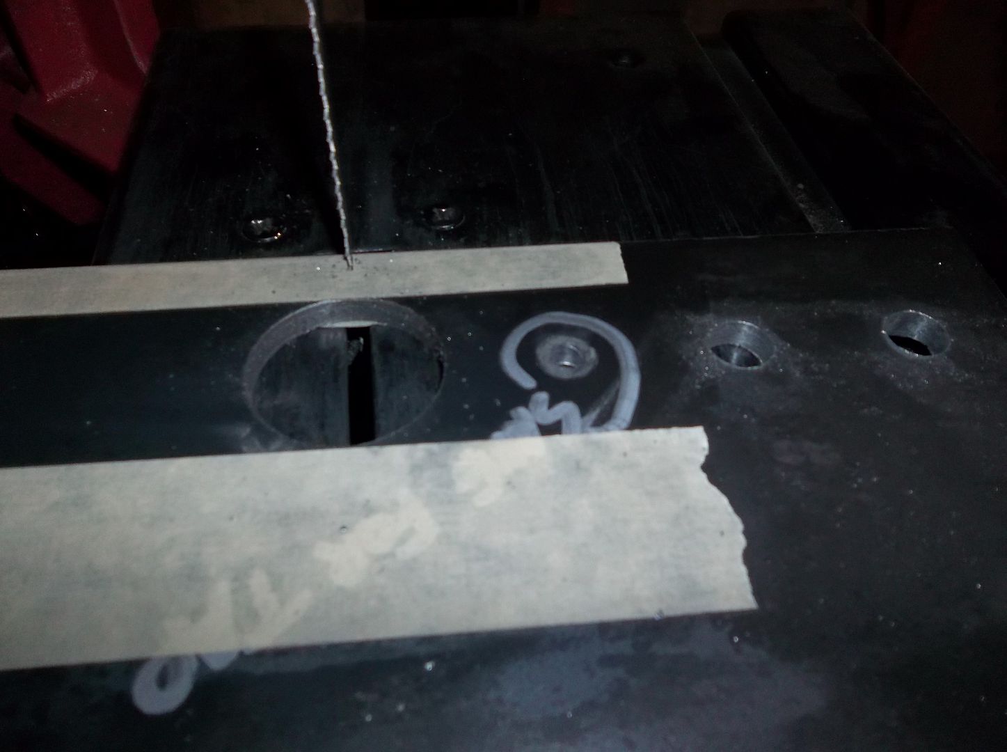
WAIT....what the heck! Yup, sawed through to the hole!
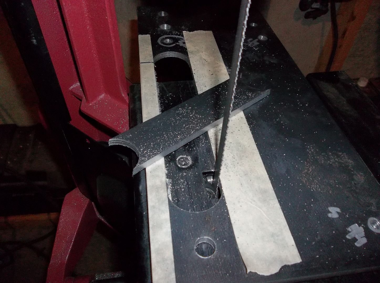
Then you can cut out the middle nice and easy on the band saw!
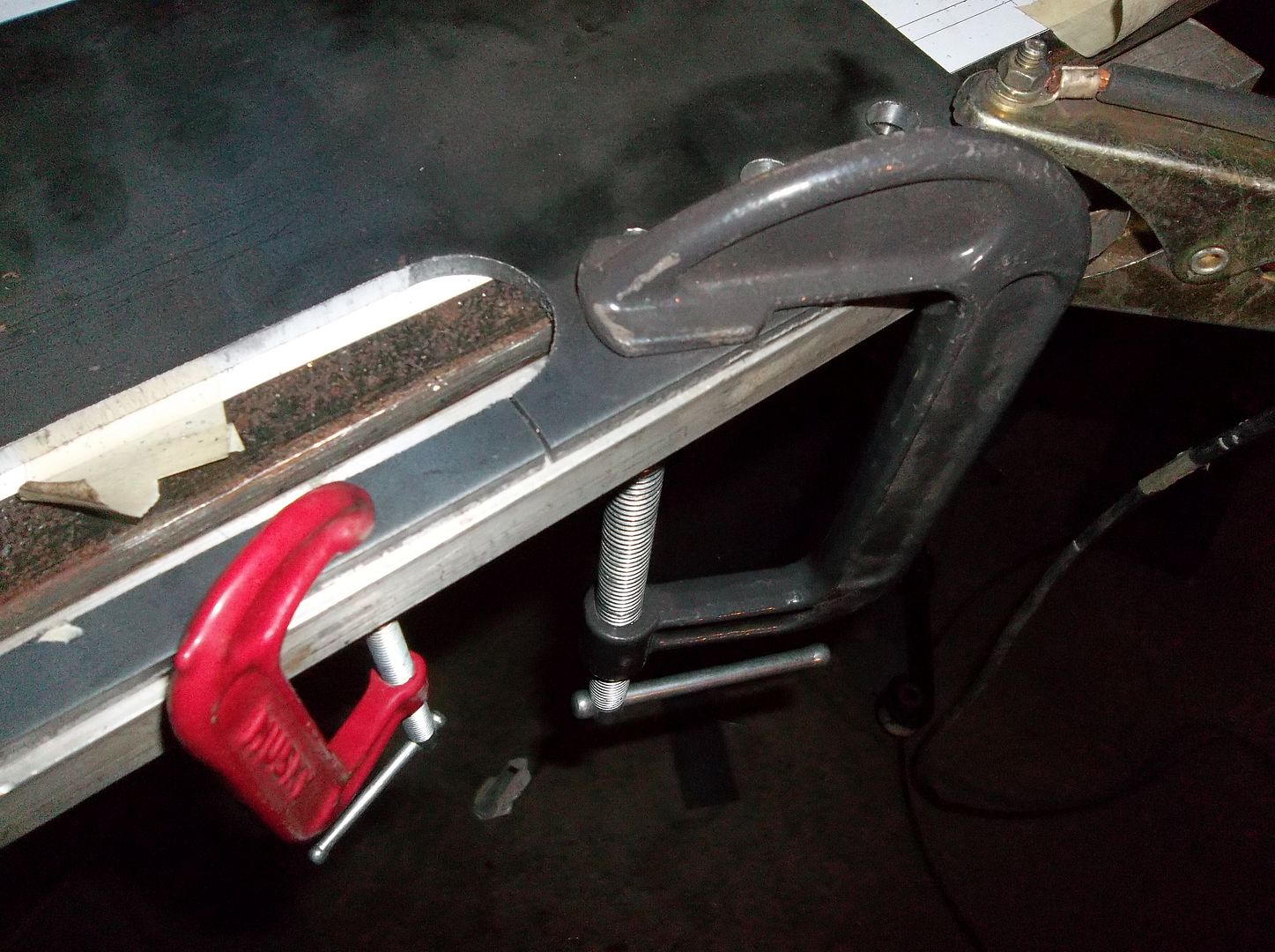
Clamp the access cut down flat and weld it back up on both sides!
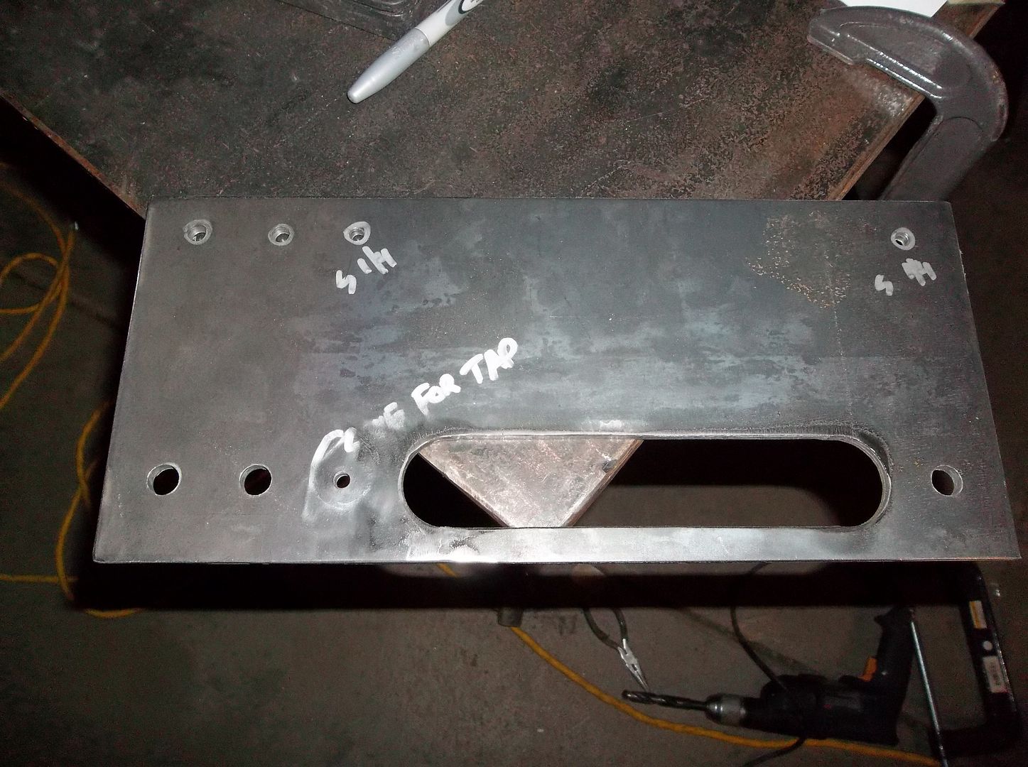
Hit it with a flap disc really quick on both sides. Then clean up the outside edges, inside edges, holes, etc. I used a file for some of the inside curves while it was clamped in the vise.
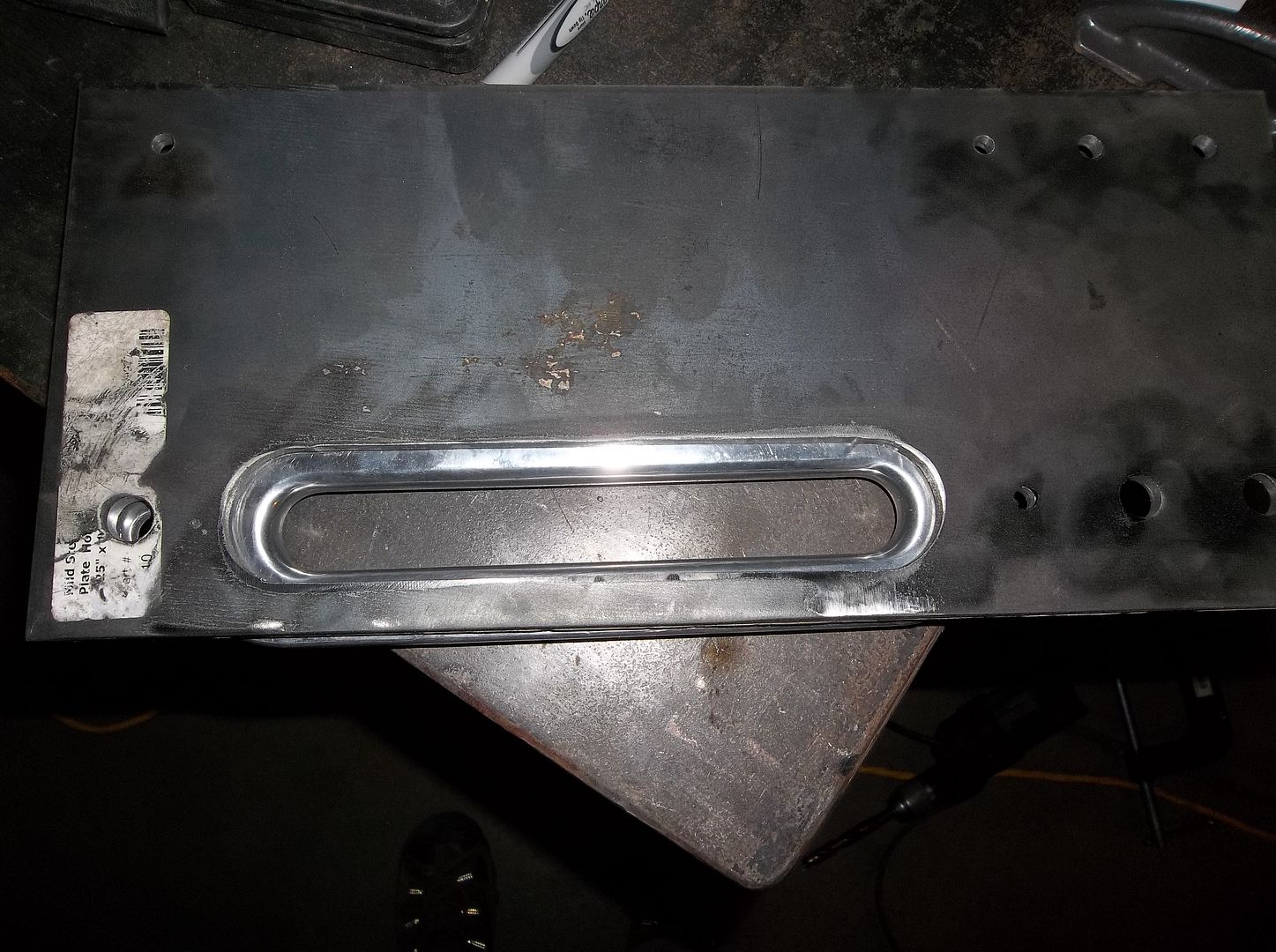
Here is the clearance with the aluminum hawse....
All in all for about an hour or so worth of work it turned out pretty nice. It's a simple boring part....but I thought you would like to see some of the little things.
I need to get some longer 1/4" bolts to hold it on the bumper for now so I can transfer some holes over the front bumper. The I will need to open up a few holes, make some sleeves for the bumper in the upper mounting hole locations, and tap the 'odd' hole for the hawse when using the Belleview winch mounting pattern. A quick trial fit on the winch and then I can tack weld the mounting plate into position and test fit the winch!

I love these paper templates. All the holes have cross hairs for center punching. I had to make a slightly different template for an adjustment on the slot for the hawse.

This is what the hole location cross hairs look like after punching. For me this work REALLY well. If you take a little time center punching the location it seems to be VERY accurate.

After I pull the template I try and mark the center punch locations with a sharpie so I can find them easier. Note: make sure you punch all the holes you need before you pull the template off. Once its pulled you can't really go back that easily. If its a complex part you can spray glue the template to the metal and wire brush what is left when your done.

My monster drill press running the 1.5" hole saw for the hawse slot. It did ok with lots of lube. This is the 12 speed version so it goes pretty slow for holes saws....not bad for about $130!

WAIT....what the heck! Yup, sawed through to the hole!

Then you can cut out the middle nice and easy on the band saw!

Clamp the access cut down flat and weld it back up on both sides!

Hit it with a flap disc really quick on both sides. Then clean up the outside edges, inside edges, holes, etc. I used a file for some of the inside curves while it was clamped in the vise.

Here is the clearance with the aluminum hawse....
All in all for about an hour or so worth of work it turned out pretty nice. It's a simple boring part....but I thought you would like to see some of the little things.
I need to get some longer 1/4" bolts to hold it on the bumper for now so I can transfer some holes over the front bumper. The I will need to open up a few holes, make some sleeves for the bumper in the upper mounting hole locations, and tap the 'odd' hole for the hawse when using the Belleview winch mounting pattern. A quick trial fit on the winch and then I can tack weld the mounting plate into position and test fit the winch!
wjeeper
Active member
Well since you have been posting over on my thread I will quit lurking and throw my $0.02 in:
I like the cage design. Its simple and has lines that are similar to the old fashioned fender mounted type "roll bars". I like that you angled the C-pillar in at the rear. It adds a touch of lateral triangulation and allows you to keep the rear toolboxes. The vertical B-pillar running through the rear wheel well is better than the last flatty I rode. That B-pillar went to the floor in front of the wheel well. It was way too far forward, pushing the seat too close to the dashboard and i bumped my head on it more than once!
I also like the idea that CRO (on PBB) had of cutting out your original cowl braces and building them out of thicker metal.......I am cataloging that one for my "benchtop build"
Random question not related to your build per-say: how low is the RPM on your drill press? The one I have is made for woodworking and cant even dream of running holesaws
VanIsle_Greg
I think I need a bigger truck!
I am no cage expert, far from it, but it makes perfect sense to me to tie the front "A" pillar cage supports into the dash structure. If you do that as mentioned you maximize the legroom in a pretty tight space already, and you are tying into one of the largest structural masses in the vehicle, the dash/firewall/cowl area.
Win win.
I am amazed at the oval you need to cut to get that tube in at that angle...crazy! Jeep is looking great!
Win win.
I am amazed at the oval you need to cut to get that tube in at that angle...crazy! Jeep is looking great!
Metcalf
Expedition Leader
Well since you have been posting over on my thread I will quit lurking and throw my $0.02 in:
I like the cage design. Its simple and has lines that are similar to the old fashioned fender mounted type "roll bars". I like that you angled the C-pillar in at the rear. It adds a touch of lateral triangulation and allows you to keep the rear toolboxes. The vertical B-pillar running through the rear wheel well is better than the last flatty I rode. That B-pillar went to the floor in front of the wheel well. It was way too far forward, pushing the seat too close to the dashboard and i bumped my head on it more than once!
I also like the idea that CRO (on PBB) had of cutting out your original cowl braces and building them out of thicker metal.......I am cataloging that one for my "benchtop build"
Random question not related to your build per-say: how low is the RPM on your drill press? The one I have is made for woodworking and cant even dream of running holesaws
Thanks for contributing!
The b-pillar will be behind the seats, not so far back it looks odd, but back enough that you shouldn't bump your head THAT much. It should also make getting in and out of the jeep a little easier too. With the low seating position and the smaller flat fender door opening....you are going to have to get up and out of it. I think it will be fairly easy to do with roll cage as a handle.
This is my mini-monster drill press...
http://www.harborfreight.com/12-speed-bench-top-drill-press-44836.html
For something that fits on a bench its pretty dang neat! It goes down to 240 rpm. It also has an 3-pulley system with an idler that could be replaced with an even larger diameter for even slower speeds if you really wanted to get crazy. I wouldn't want to drill 1" holes all day long with it, but for garage fabrication its SOOOO much better than a hand drill. At $130 it's a good value. It ran the 1.5" hole saw through 1/4" material just fine. You need to clamp stuff like that down very good to minimize chatter and vibration as much as you can. I ran a .625" drill bit with it the other day too. It did just fine. I also drilled 1/2" holes through my u-bolt jig plate with no pilot hole to see if it could do it.....and it did. That thing is over 1/2" thick I think.
I probably won't cut out the existing cowl brace, but rather plate over the top of it. I think I have a design that will be fairly simple and be strong enough....yet not take up any extra foot room.
Metcalf
Expedition Leader
I am no cage expert, far from it, but it makes perfect sense to me to tie the front "A" pillar cage supports into the dash structure. If you do that as mentioned you maximize the legroom in a pretty tight space already, and you are tying into one of the largest structural masses in the vehicle, the dash/firewall/cowl area.
Win win.
I am amazed at the oval you need to cut to get that tube in at that angle...crazy! Jeep is looking great!
Yup, a 15-16 degree cut takes up a lot of space! That should allow the A-pillar to follow the windshield almost exactly. I do think that I will have to relocate/remake a few things on the windshield to get all the stock features to work.
Metcalf
Expedition Leader
Just a bit of progress....but progress is progress.
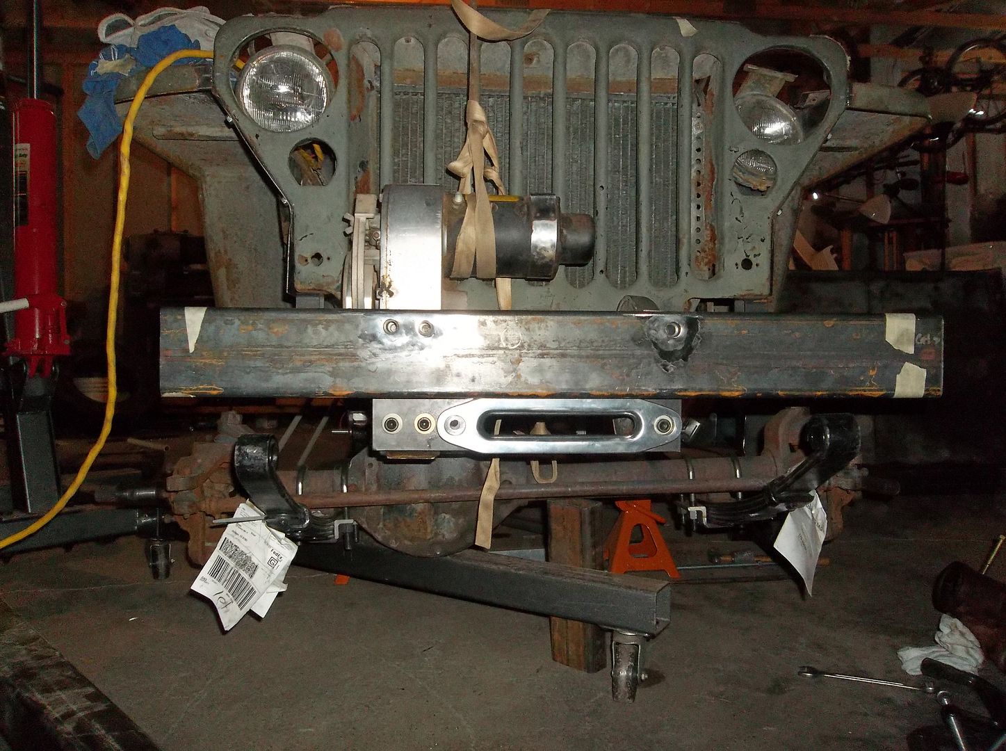
I got the winch mount mostly finished up ( for the mock up ). I will final weld everything during the tear down so I can roll the frame over and stuff. Not too much super trick stuff, but I did add a few details....
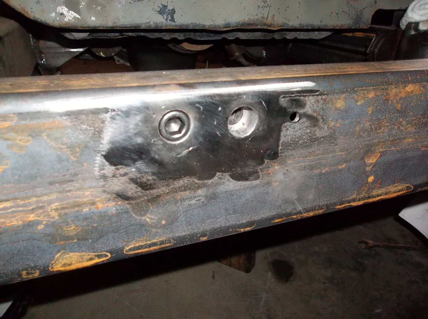
The top three mounting hardware holes for the Belleview winch where made to sit flush with the front of the bumper. I just thought it will look cleaner in the end.
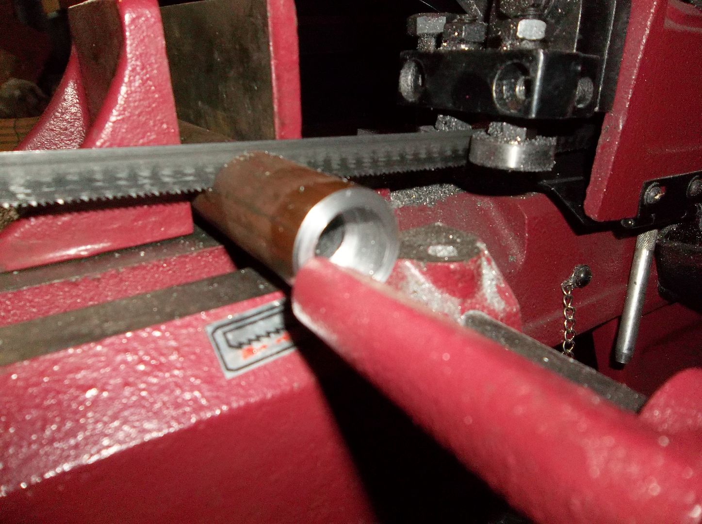
I tool some 1" solid stock, drilled the center to 1/2", and then bored to 11/16 for a 7/16-14 SHCS to fit in basically flush with the face. I chamfered the ends for a good welding surface. I drilled the face of the bumper with a 1" hole saw and then welded these sleeves into place.
Just one of those little details that took some time...
When I bolted up the winch I did a test fit of the steering box and was lucky to find that it will JUST clear the winch with the pitman arm on full lock. I am going to shift the steering box off the frame rail slightly also so that the pitman arm doesn't get to friendly with the drivers side spring when turning hard right.
I made a template for the steering box but forgot it on my desk at the office. The top two mounting bolts will be done similar to the top bolts of the winch mount where the bolt heads will be flush to the side of the frame. This will give the tire a nice smooth surface to rub if it comes to that. The bottom two bolts fall below the bottom edge of the frame and will be on a simple mount under the frame with some sleeves to space the mounts away from the frame as needed.
More soon.....

I got the winch mount mostly finished up ( for the mock up ). I will final weld everything during the tear down so I can roll the frame over and stuff. Not too much super trick stuff, but I did add a few details....

The top three mounting hardware holes for the Belleview winch where made to sit flush with the front of the bumper. I just thought it will look cleaner in the end.

I tool some 1" solid stock, drilled the center to 1/2", and then bored to 11/16 for a 7/16-14 SHCS to fit in basically flush with the face. I chamfered the ends for a good welding surface. I drilled the face of the bumper with a 1" hole saw and then welded these sleeves into place.
Just one of those little details that took some time...
When I bolted up the winch I did a test fit of the steering box and was lucky to find that it will JUST clear the winch with the pitman arm on full lock. I am going to shift the steering box off the frame rail slightly also so that the pitman arm doesn't get to friendly with the drivers side spring when turning hard right.
I made a template for the steering box but forgot it on my desk at the office. The top two mounting bolts will be done similar to the top bolts of the winch mount where the bolt heads will be flush to the side of the frame. This will give the tire a nice smooth surface to rub if it comes to that. The bottom two bolts fall below the bottom edge of the frame and will be on a simple mount under the frame with some sleeves to space the mounts away from the frame as needed.
More soon.....
Metcalf
Expedition Leader
Some progress.....finally!
Tonight I got the steering box mount mostly built.....
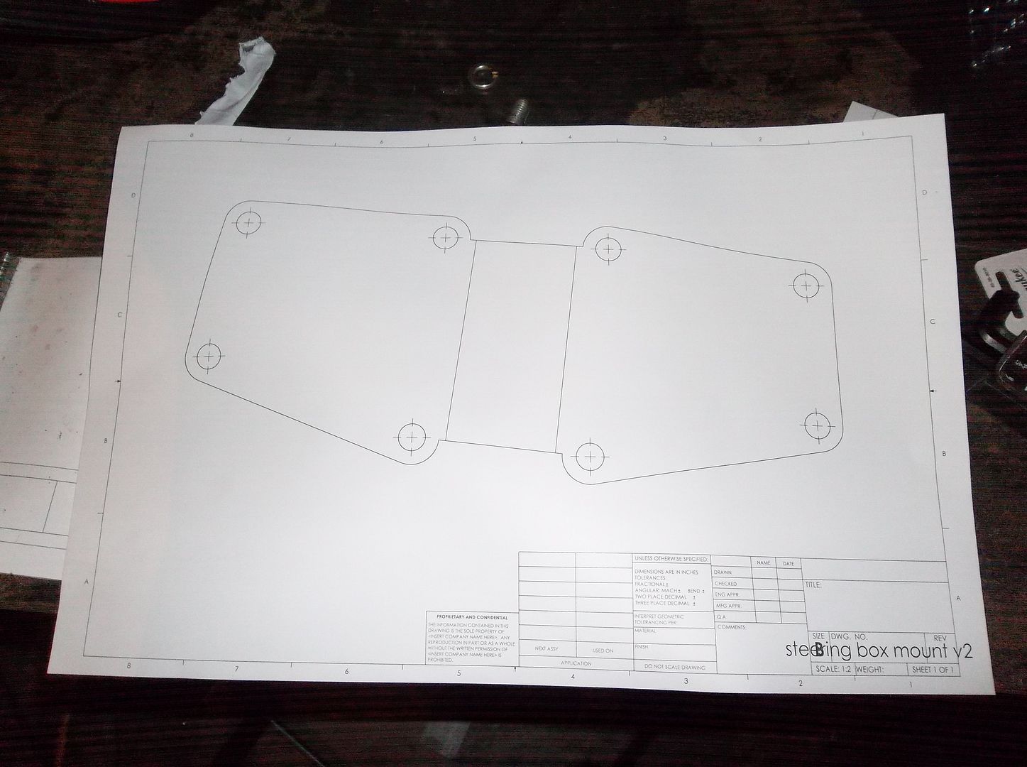
Hey look! Another paper template....
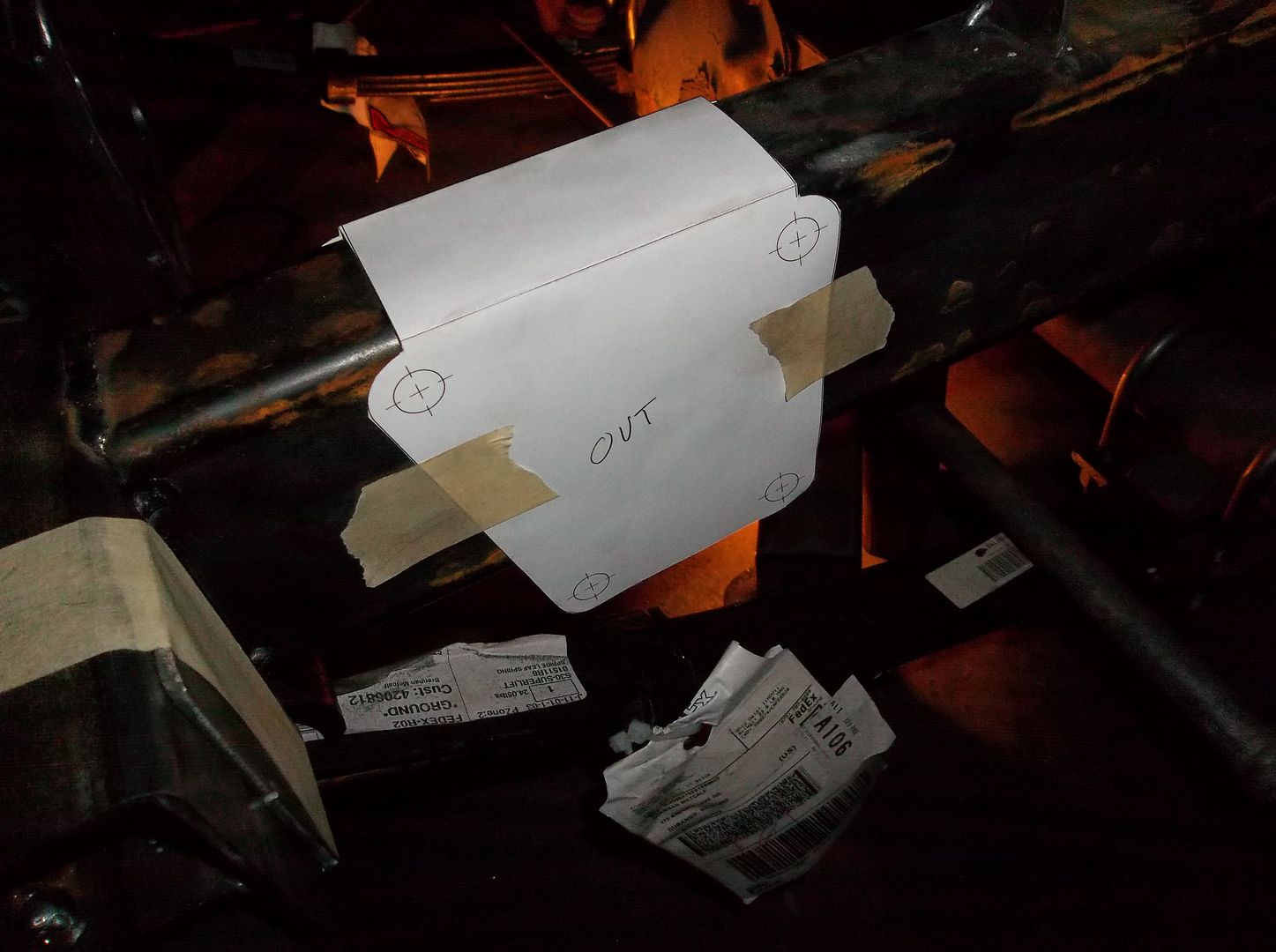
Cut, Cut, fold, fold.....
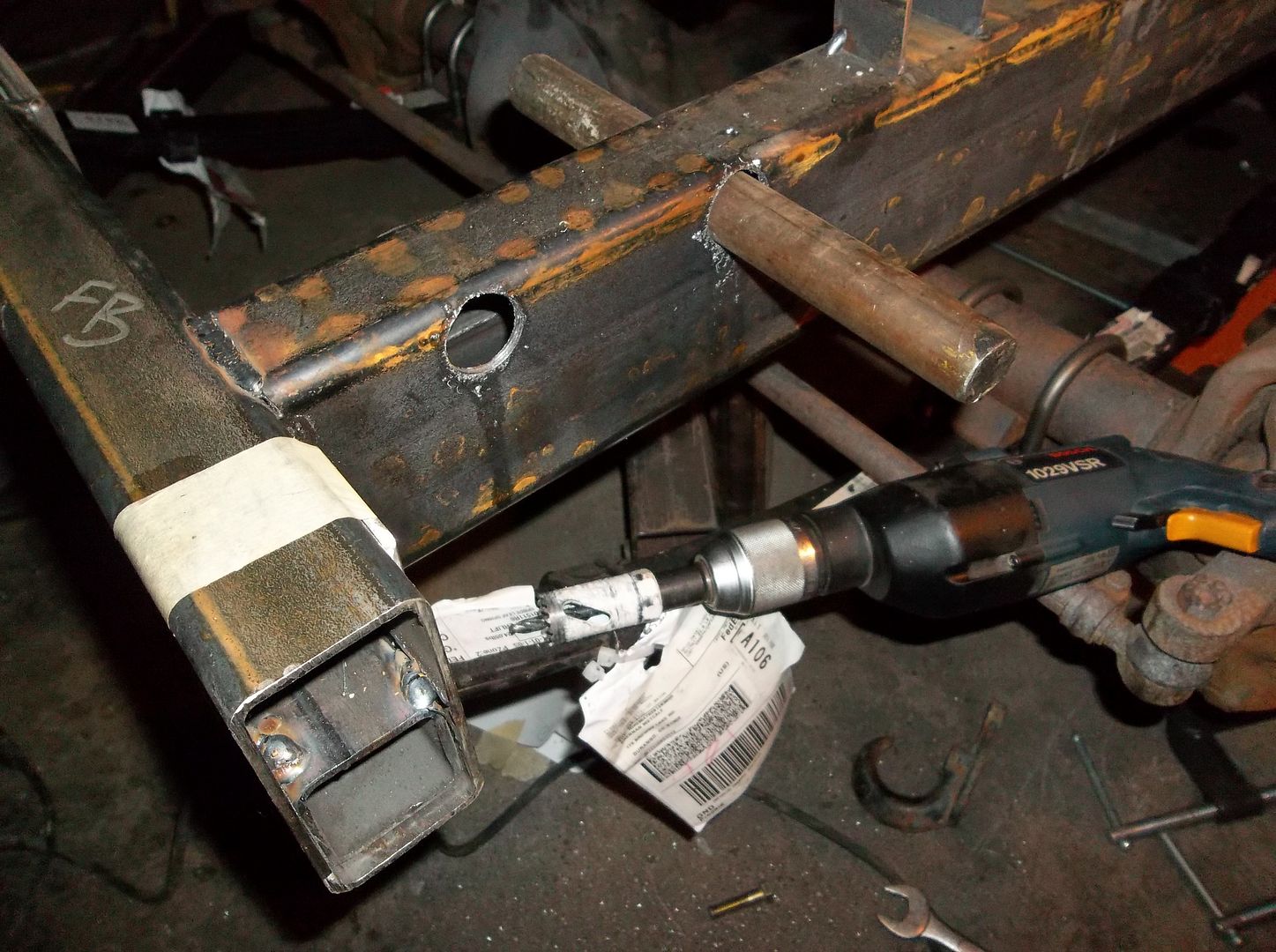
Center punch the upper holes on the inside and outside. Mark them when you take the paper template off. Drill those four locations with a 1/4" bit. The from the outside to the inside with a 1" hole saw. With the pilot hole on the inside you can drill all the way through from the outside without too many worries about the holes being off.
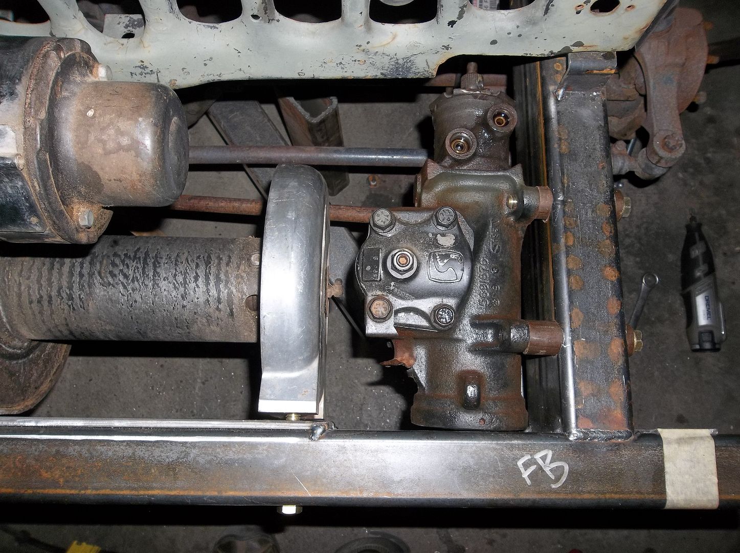
I made some more inserts for the frame out of 1" round bar stock. 1/2" hole all the way through the middle and a 11/16 counterbore on the outside for a SHCS to sit in flush. I didn't have the proper hardware for the flush bolts so I used regular hardware. Once the mounts are fully welded the sleeves will be flush with the outside of the frame and the bolt head recessed. This will give a nice smooth surface for the tire to rub on when turning hard lock.
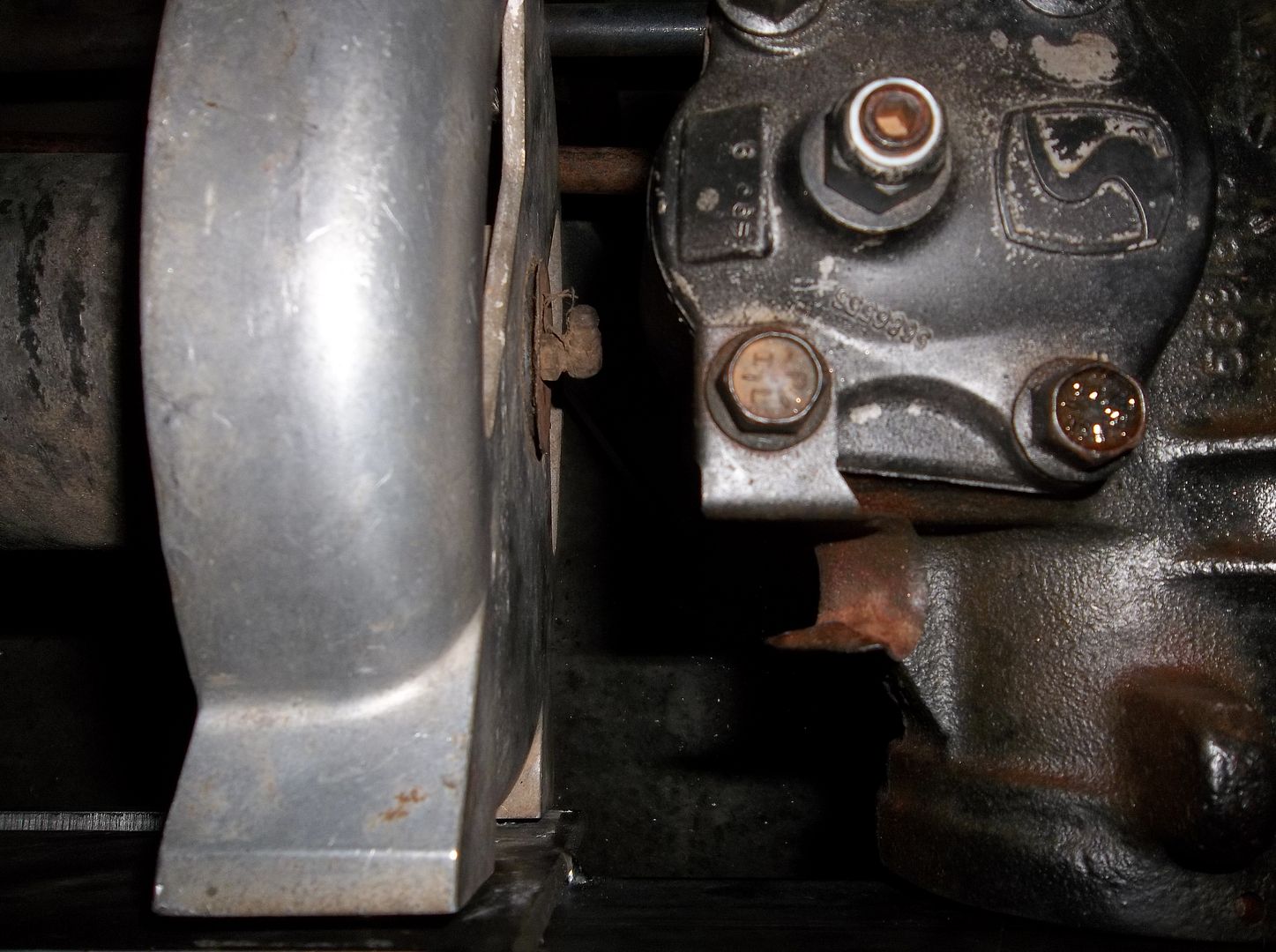
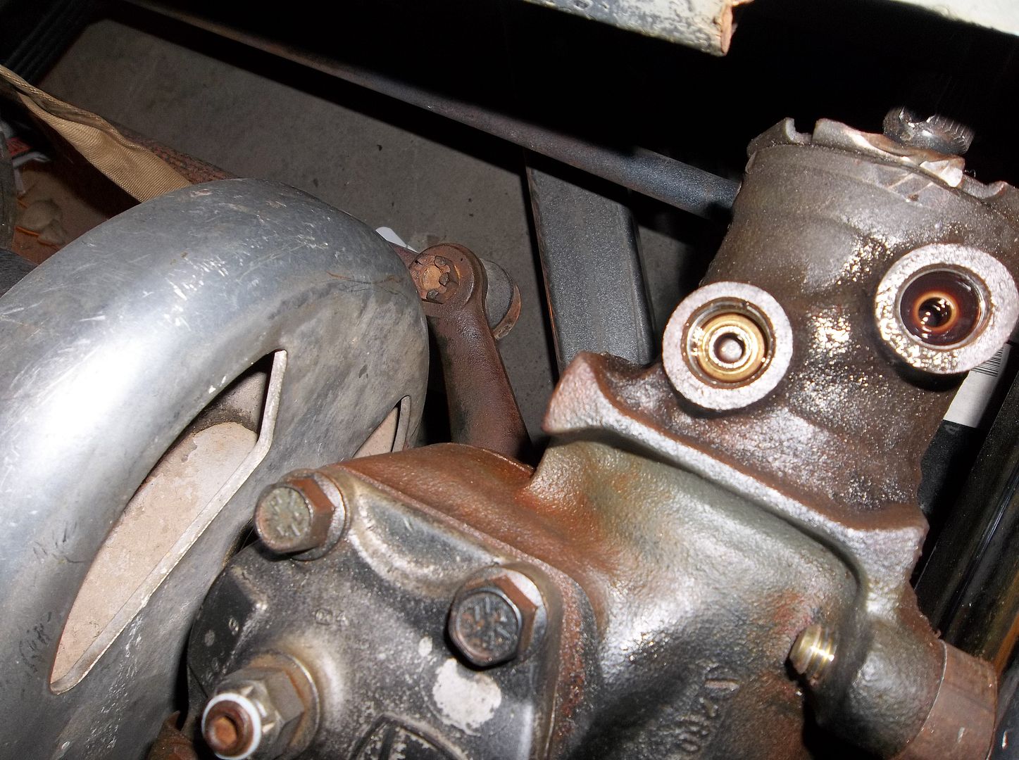
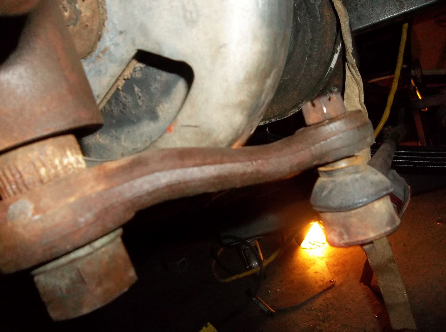
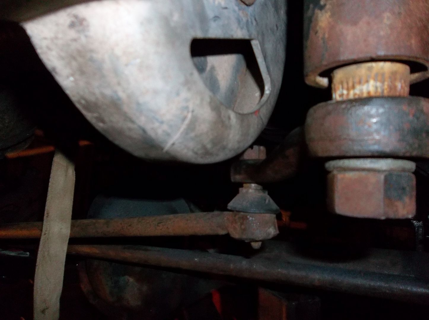
Not a lot of room in there with that big winch. The pitman arm just clears the winch on full lock....and just clears the side of the spring on opposite lock. Not a ton of clearance but everything fit!
Tomorrow I need to make a tab and some spacers to capture the bottom two mounting bolts on the steering box. Both those bolts are below the frame so no need for a fancy sleeve.
Tonight I got the steering box mount mostly built.....

Hey look! Another paper template....

Cut, Cut, fold, fold.....

Center punch the upper holes on the inside and outside. Mark them when you take the paper template off. Drill those four locations with a 1/4" bit. The from the outside to the inside with a 1" hole saw. With the pilot hole on the inside you can drill all the way through from the outside without too many worries about the holes being off.

I made some more inserts for the frame out of 1" round bar stock. 1/2" hole all the way through the middle and a 11/16 counterbore on the outside for a SHCS to sit in flush. I didn't have the proper hardware for the flush bolts so I used regular hardware. Once the mounts are fully welded the sleeves will be flush with the outside of the frame and the bolt head recessed. This will give a nice smooth surface for the tire to rub on when turning hard lock.


Not a lot of room in there with that big winch. The pitman arm just clears the winch on full lock....and just clears the side of the spring on opposite lock. Not a ton of clearance but everything fit!
Tomorrow I need to make a tab and some spacers to capture the bottom two mounting bolts on the steering box. Both those bolts are below the frame so no need for a fancy sleeve.
Metcalf
Expedition Leader
Thanks! It is indeed a TIGHT fit on the front end with all that stuff. The winch is sunken to get the weight nice and low, plus it won't block the radiator. The steering box is in a position where it is low enough to work lock to lock but high enough to be protected by the front bumper.
Still lots to do....but I can kinda see light at the end of the tunnel.
Seats, pedal mounting, steering column/shaft/wheel, shackle mounts, shackles, etc.....all coming soon.
Still lots to do....but I can kinda see light at the end of the tunnel.
Seats, pedal mounting, steering column/shaft/wheel, shackle mounts, shackles, etc.....all coming soon.
Metcalf
Expedition Leader
Just a bit more.....
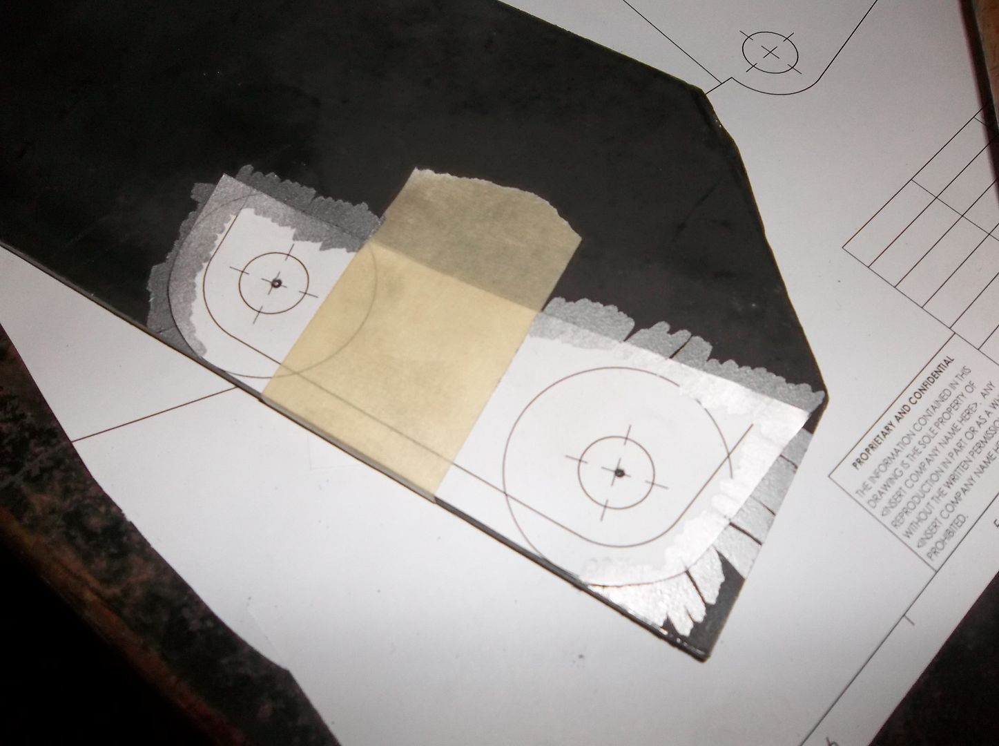
A few tricks here. A paper template...yeah, you know that one already. Center punch the holes...yeah yeah. To mark the outside edges I 'wipe' a silver sharpie around the edge from the paper off to the steel. This gives me a nice edge.....
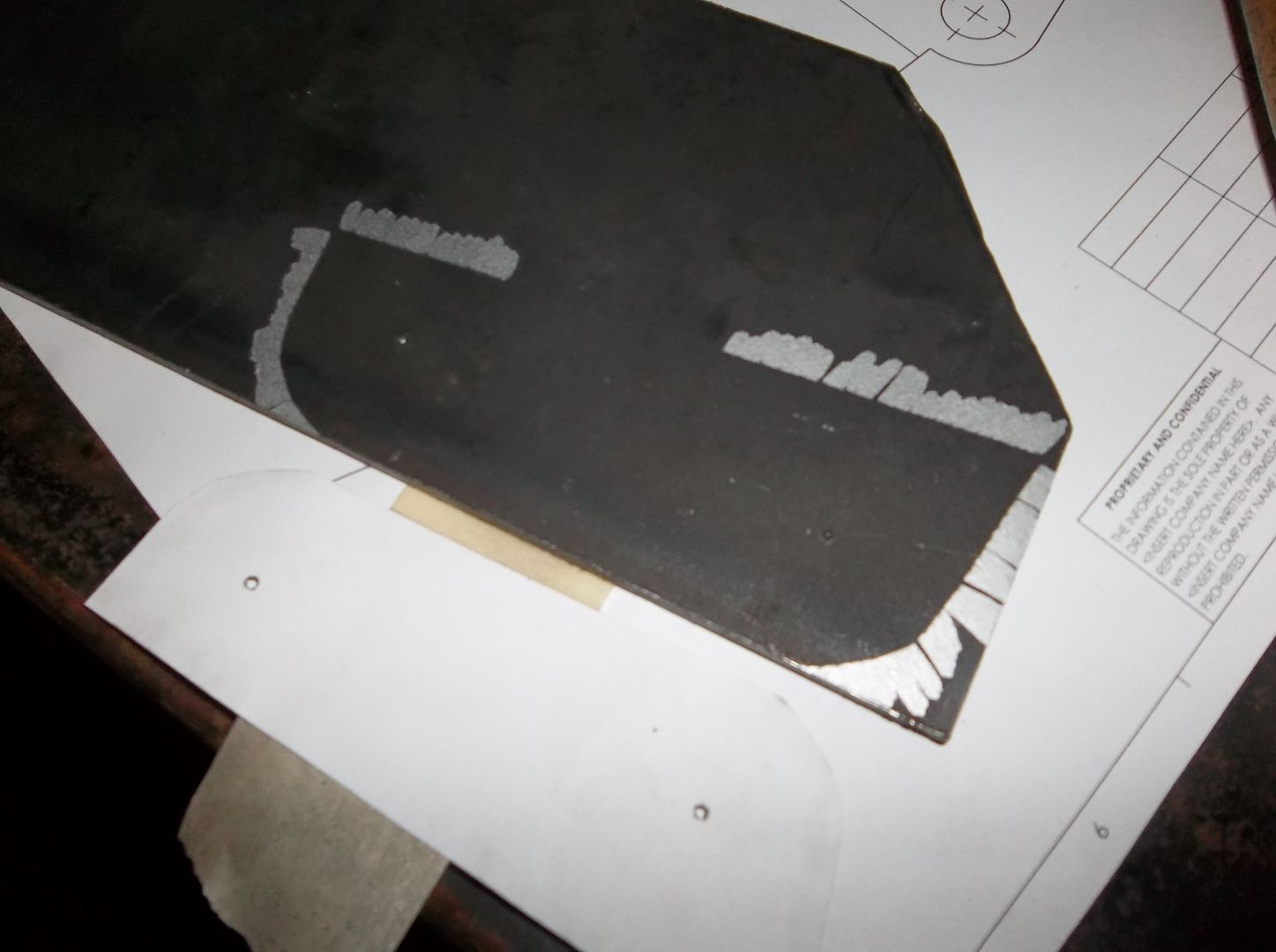
I usually just spray glue the template down....but I couldn't find the spray glue dang it! So I taped it down. On the 'missing' section I just ran another piece of masking tape down that entire straight edge to use as a guide to cut it out on the bandsaw. I generally punch and drill the holes before I cut the part out if I can.
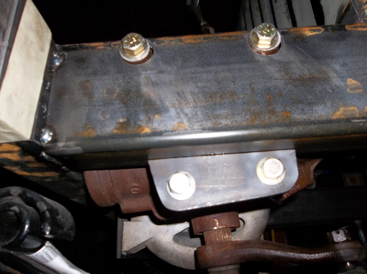
It sure fit nice! I cut the straight lines on the bandsaw and then used a flap disc to round off the corners to where the silver sharpie mark was. Overall the measurements for the steering box I took seemed DEAD on. I will try and see if I can post a pdf template or two for this kinda stuff.
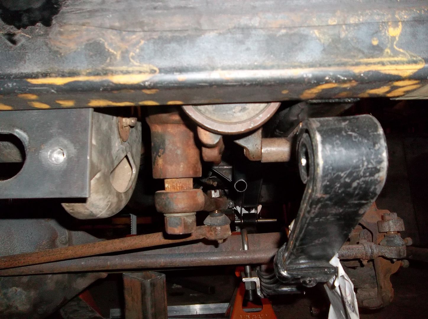
Here you can see the final position of the steering box tucked up nice and safe behind the front bumper. I made some simple 1.5" long spacers for the lower mounting holes so the lower bracket was on the flat bottom of the frame. This will let me weld both sides after mock up. I will also add a perpendicular gusset between the bracket and the frame when I fully weld the frame ( inbetween the mounting bolts ). I didn't want to weld upsidedown.....ick.
The mount turned out really nice so far I think. All the bolts come in and out very easy just using your fingers.....I like that.
Preview of things to come....

A few tricks here. A paper template...yeah, you know that one already. Center punch the holes...yeah yeah. To mark the outside edges I 'wipe' a silver sharpie around the edge from the paper off to the steel. This gives me a nice edge.....

I usually just spray glue the template down....but I couldn't find the spray glue dang it! So I taped it down. On the 'missing' section I just ran another piece of masking tape down that entire straight edge to use as a guide to cut it out on the bandsaw. I generally punch and drill the holes before I cut the part out if I can.

It sure fit nice! I cut the straight lines on the bandsaw and then used a flap disc to round off the corners to where the silver sharpie mark was. Overall the measurements for the steering box I took seemed DEAD on. I will try and see if I can post a pdf template or two for this kinda stuff.

Here you can see the final position of the steering box tucked up nice and safe behind the front bumper. I made some simple 1.5" long spacers for the lower mounting holes so the lower bracket was on the flat bottom of the frame. This will let me weld both sides after mock up. I will also add a perpendicular gusset between the bracket and the frame when I fully weld the frame ( inbetween the mounting bolts ). I didn't want to weld upsidedown.....ick.
The mount turned out really nice so far I think. All the bolts come in and out very easy just using your fingers.....I like that.
Preview of things to come....

Metcalf
Expedition Leader
Time for some brakes!
I went a little bit different route than I see most people go. I wanted the disc brakes to be the same at all 4 corners. My full float rear kit is going to use all the same spindles, bearing hubs, studs, etc. I also wanted slip OVER rotors that would work on the stock jeep drum brake bearing hubs. I also wanted the parts to be cheap and easy to find at any Autozone or other parts house.
I still need to make a bracket to adapt from the 6-bolt spindle bolt pattern to the caliper. I didn't want to have a complex mount that would require bending, sleeves for floating pins etc. I looked at all the other options I could find, but decided to make my own. Big surprise, I know!
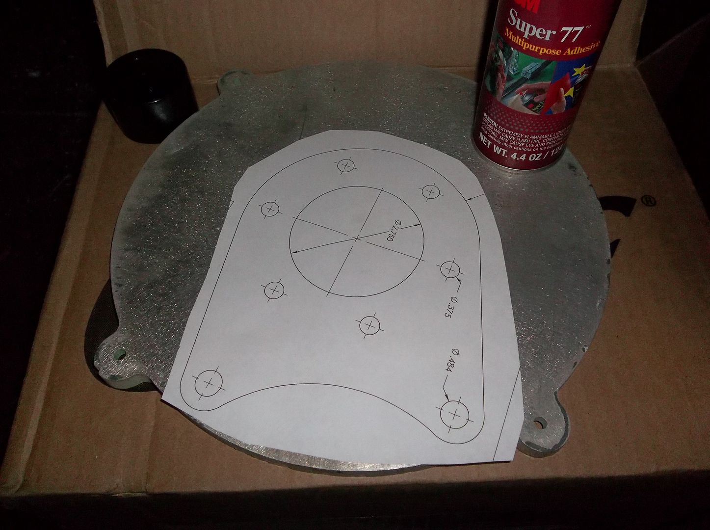
So a little time on the computer and I had a pattern to print out. I glued this one to the prototype bracket material, 3/8" aluminum plate scrap from work. The aluminum made it MUCH quicker to knock out a prototype test bracket to check all my measurements. I will likely get the final brackets waterjet cut.
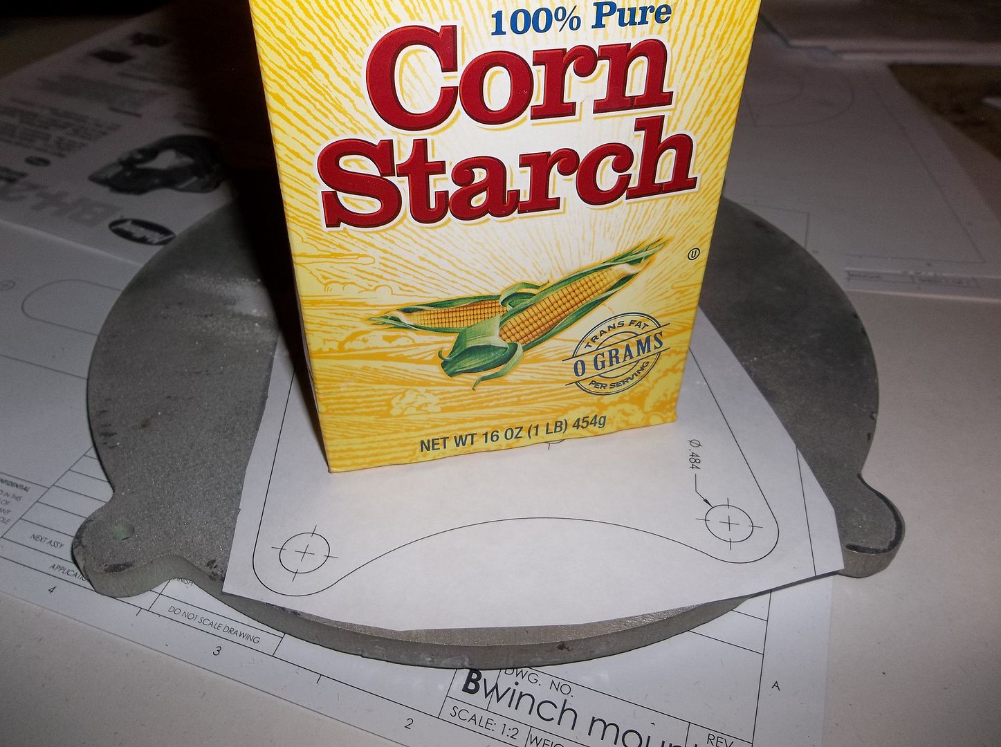
The glue outside the template gets everything all sticky and its kind of pain to work around. I raised the kitchen for some corn starch, rub that over the exposed areas of tacky glue and it takes away the tacky sticky feeling.
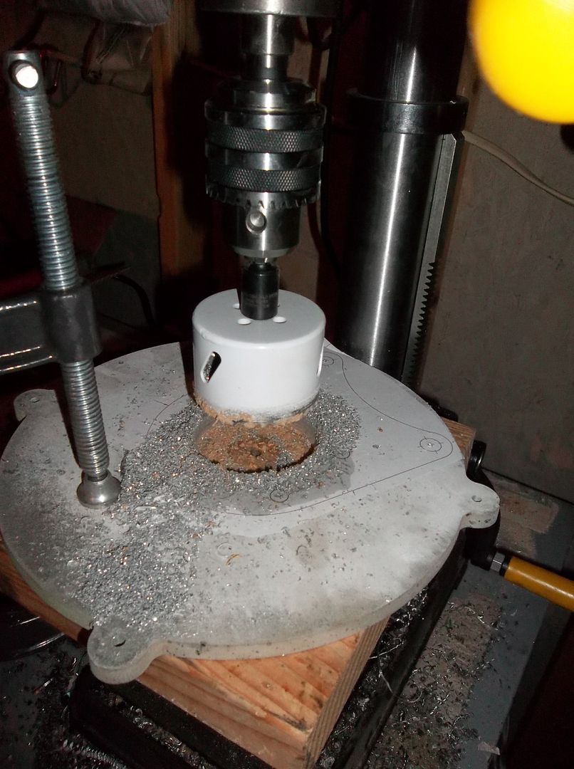
This was working my mini-drill press pretty hard.....but it did run a 2.75" holes saw through the 3/8" aluminum. I couldn't find my WD40, that stuff works great as aluminum cutting fluid....dang it.

Once all the other holes where drilled I cut it out on the mighty bandsaw, that took a little bit......
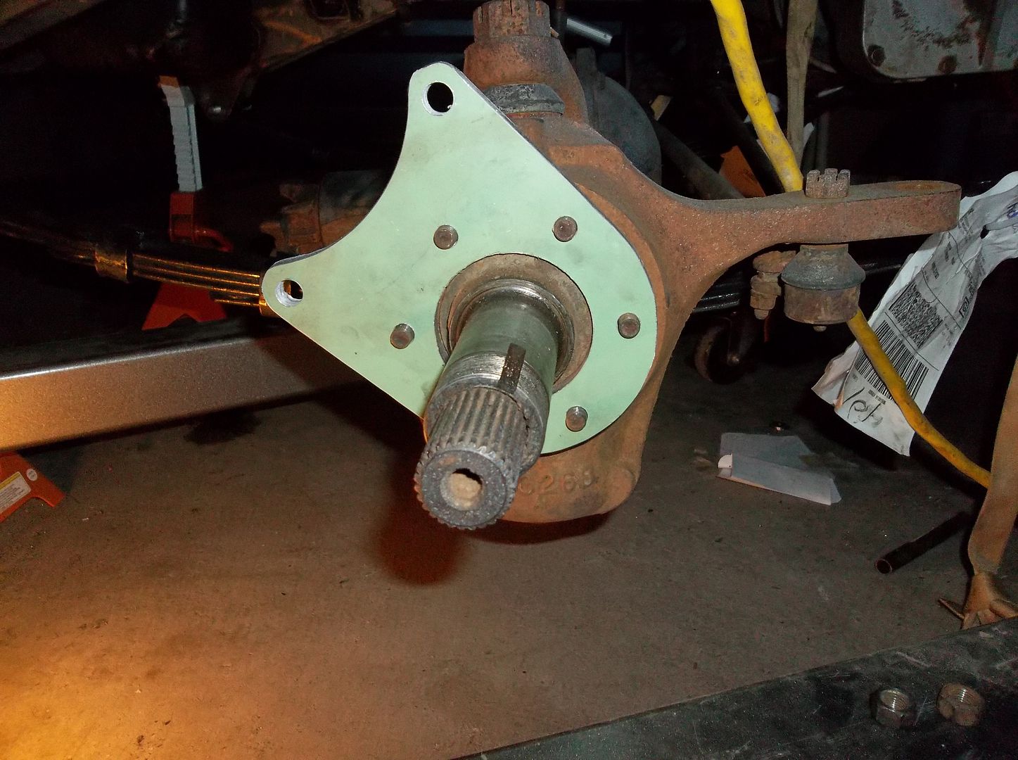
It fit on the spindle just like it was suppose to....perfect fit for a paper template and transferring the holes over by hand with just cross hairs on the paper. I designed the bracket to clock the caliper back at 45 degress so that the bleed fitting would be right up on top.
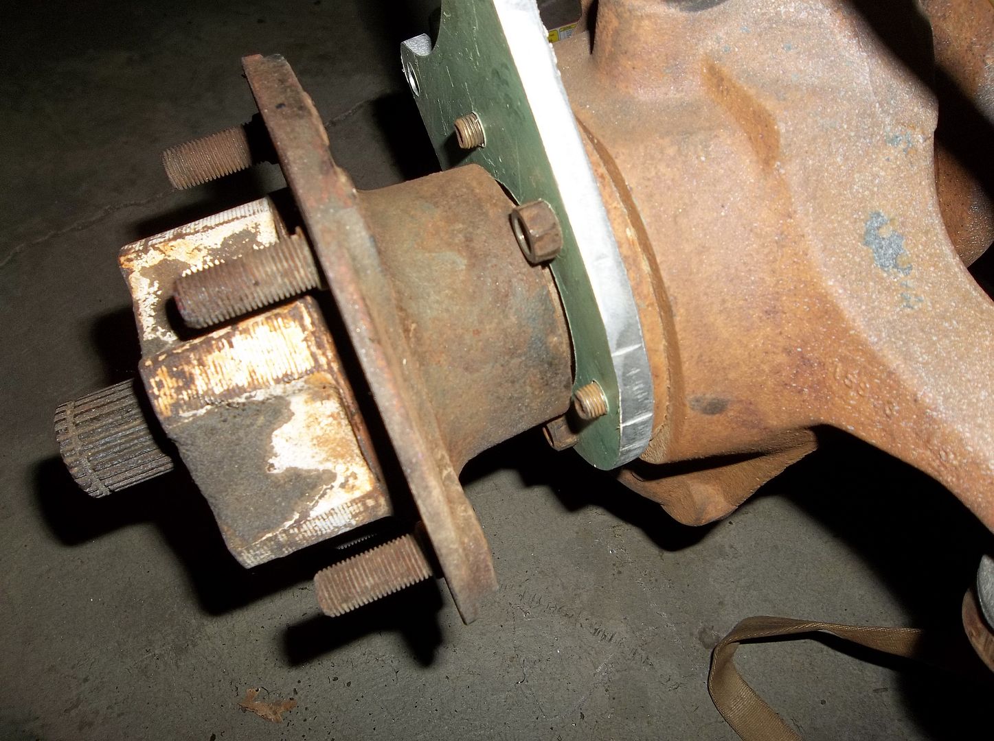
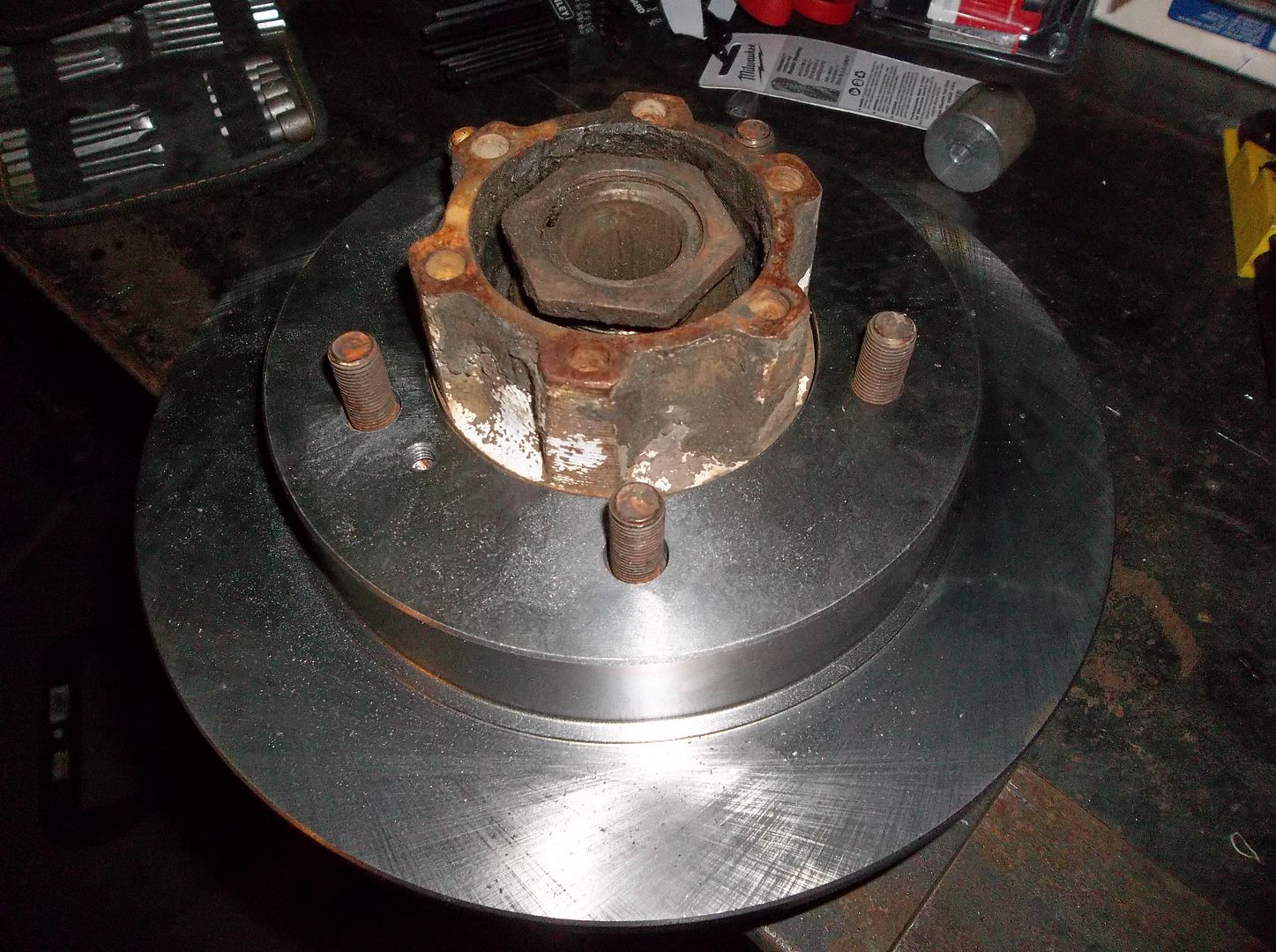
The wheel bearing hub is a tight fit, but it fits! There is still room for the spindle seal on the back of the bearing hub without any modification. The factory knuckle to spindle studs are a little short....
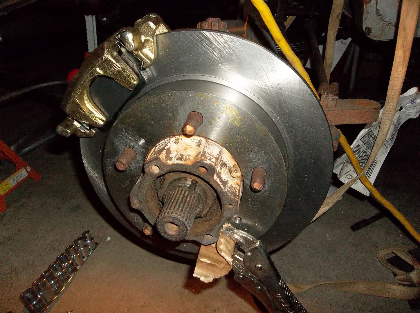
Here is is all assembled. It worked out GREAT. I calculated the position of the pad on the caliper just right. It is about 1/16" from the outside edge of the caliper. Eveything bolted together just like it was suppose to.....but.....
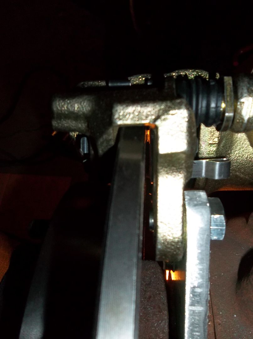
The caliper spacing is just a hair off. The caliper needs to be .060 further out. I am going to change the caliper mount to use a .250" thick main body with a .188 shim at the mounting bolt holes. This will space the caliper out the needed .060 further out. It still uses stock size material so I won't have to fly cut anything. The thinner main body will also give be .125" more clearance t the spindle mounting nuts and .125" more thread engagement on the spindle mounting studs. This should let me use the factory studs without worry. They are a fine thread 3/8 t-bolt thing so finding slightly longer ones might be a pain in the rear.
So the magic formula so far.....
1990 Geo Tracker or Suzuki Sidekick rotors....approx $20 each. I had to drill the 5-lug holes out to .609 with a 39/64 drill bit to get the wheel stud holes in the rotor to seat over over the base of the wheel stud. It took just a few minutes on the drill press. That was the only mod I had to make to the rotors. They just slide right over the bearing hub and sit flat on the face.
1990 Geo tracker or Suzuki Sidekick calipers...approx $60 each. They are a factory match to the above rotor so you know they are going to fit well. The calipers come with an integrated caliper mount that allows the caliper to float in and out on the rotor as the pads where. This caliper mount bolts on with two holes that are already threaded so the hole in the adapter plate just need to be a hole. The mounting bolt size is a little odd being M12-1.25 and you need to make sure the bolts are not long enough to pass too far through the caliper mount and into the rotor. The calipers are 1.89" bore so that needs to be figured into your master cylinder bore choice.
I know there are bigger better stronger faster brake options, but for me this made the most sense. It isn't a race jeep, I just needed a simple affordable disc brake system. I really like how simple and compact the system is. The slip on rotor makes things SOOOO easy. You do not have to press in some new wheel studs from the back side of the flange to hold the rotor in place like with some other conversion. This should make the rotor replacement down the road a piece of cake.
Once other bonus to this style disc conversion is that it should allow me to treat the spindle and bearing hub as a unit-bearing. Once you remove two mounting caliper bolts, move the caliper out of the way, and slip off the wheel bearing you can then just undo the six nuts holding the spindle on and remove the whole unit without having to mess with the spindle nut or wheel bearing at all. You will have to also remove your drive flange snap ring or nut....or remove the hub if you don't want to pull the entire axle assembly out at the same time!
I will go into the master cylinder choice and plumbing when I get to that point in the build......
I went a little bit different route than I see most people go. I wanted the disc brakes to be the same at all 4 corners. My full float rear kit is going to use all the same spindles, bearing hubs, studs, etc. I also wanted slip OVER rotors that would work on the stock jeep drum brake bearing hubs. I also wanted the parts to be cheap and easy to find at any Autozone or other parts house.

I still need to make a bracket to adapt from the 6-bolt spindle bolt pattern to the caliper. I didn't want to have a complex mount that would require bending, sleeves for floating pins etc. I looked at all the other options I could find, but decided to make my own. Big surprise, I know!
So a little time on the computer and I had a pattern to print out. I glued this one to the prototype bracket material, 3/8" aluminum plate scrap from work. The aluminum made it MUCH quicker to knock out a prototype test bracket to check all my measurements. I will likely get the final brackets waterjet cut.

The glue outside the template gets everything all sticky and its kind of pain to work around. I raised the kitchen for some corn starch, rub that over the exposed areas of tacky glue and it takes away the tacky sticky feeling.

This was working my mini-drill press pretty hard.....but it did run a 2.75" holes saw through the 3/8" aluminum. I couldn't find my WD40, that stuff works great as aluminum cutting fluid....dang it.

Once all the other holes where drilled I cut it out on the mighty bandsaw, that took a little bit......

It fit on the spindle just like it was suppose to....perfect fit for a paper template and transferring the holes over by hand with just cross hairs on the paper. I designed the bracket to clock the caliper back at 45 degress so that the bleed fitting would be right up on top.

The wheel bearing hub is a tight fit, but it fits! There is still room for the spindle seal on the back of the bearing hub without any modification. The factory knuckle to spindle studs are a little short....

Here is is all assembled. It worked out GREAT. I calculated the position of the pad on the caliper just right. It is about 1/16" from the outside edge of the caliper. Eveything bolted together just like it was suppose to.....but.....

The caliper spacing is just a hair off. The caliper needs to be .060 further out. I am going to change the caliper mount to use a .250" thick main body with a .188 shim at the mounting bolt holes. This will space the caliper out the needed .060 further out. It still uses stock size material so I won't have to fly cut anything. The thinner main body will also give be .125" more clearance t the spindle mounting nuts and .125" more thread engagement on the spindle mounting studs. This should let me use the factory studs without worry. They are a fine thread 3/8 t-bolt thing so finding slightly longer ones might be a pain in the rear.
So the magic formula so far.....
1990 Geo Tracker or Suzuki Sidekick rotors....approx $20 each. I had to drill the 5-lug holes out to .609 with a 39/64 drill bit to get the wheel stud holes in the rotor to seat over over the base of the wheel stud. It took just a few minutes on the drill press. That was the only mod I had to make to the rotors. They just slide right over the bearing hub and sit flat on the face.
1990 Geo tracker or Suzuki Sidekick calipers...approx $60 each. They are a factory match to the above rotor so you know they are going to fit well. The calipers come with an integrated caliper mount that allows the caliper to float in and out on the rotor as the pads where. This caliper mount bolts on with two holes that are already threaded so the hole in the adapter plate just need to be a hole. The mounting bolt size is a little odd being M12-1.25 and you need to make sure the bolts are not long enough to pass too far through the caliper mount and into the rotor. The calipers are 1.89" bore so that needs to be figured into your master cylinder bore choice.
I know there are bigger better stronger faster brake options, but for me this made the most sense. It isn't a race jeep, I just needed a simple affordable disc brake system. I really like how simple and compact the system is. The slip on rotor makes things SOOOO easy. You do not have to press in some new wheel studs from the back side of the flange to hold the rotor in place like with some other conversion. This should make the rotor replacement down the road a piece of cake.
Once other bonus to this style disc conversion is that it should allow me to treat the spindle and bearing hub as a unit-bearing. Once you remove two mounting caliper bolts, move the caliper out of the way, and slip off the wheel bearing you can then just undo the six nuts holding the spindle on and remove the whole unit without having to mess with the spindle nut or wheel bearing at all. You will have to also remove your drive flange snap ring or nut....or remove the hub if you don't want to pull the entire axle assembly out at the same time!
I will go into the master cylinder choice and plumbing when I get to that point in the build......
Similar threads
- Replies
- 7
- Views
- 823
- Replies
- 4
- Views
- 2K
- Replies
- 65
- Views
- 6K

