Ski Bum Truck V2.0, F450 Rough Road RV

Alloy

Well-known member
The best way is to individually connect each 12V bank with identical length cables to pos/neg buss bars or terminal on the fuse/shunt and protect each bank with a fuse (200A) and a disconnect.

Excessive but these are the things one does after seeing what happen to a bank on the rare occasion a cell shorts.

The disconnects allow each bank to be equalized seperatly.
 

dwh

Tail-End Charlie
And here I thought the red on the ends actually meant something...ah well.

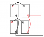
So the upper two is a series string, and the bottom two another series string.

Well, the connections shown in the pic would have one string doing (most of) the work.

For instance, power would flow from upper right battery neg through jumper to lower right batt neg, through lower right batt to pos, jumper to lower left neg, through batt to lower left pos. Wouldn't flow through the upper string at all.

Or, could just as easily flow though the upper string and bypass the lower. Really just depends on which string has the lower resistance.

But that's always the problem with parallel...the least resistance does most of the work, wears out faster until it has a higher resistance, then whichever one now has the least resistance takes over doing most of the work. Ping-ponging and wearing out the whole bank faster.

But ya run whatcha brung. So yea, the way you have it in the pic is the best for what you've got.

(Unless there's a way to make it Method 4...but I'd have to think about that for a while.)
 

dwh

Tail-End Charlie
In that situation, I might consider splitting the 1/0 to different posts...but again, would need to think about that and right now gotta go do something.
 

java

Expedition Leader
Red was just on all the jumpers I bought..... I rolled with it.

I think pulling off the positive and negatives like I had shown above will balance it as well as I am willing. Running a bump of jumpers to posts I just don't have room for.

This just happened.
49461784687_3bd26a8dc8_b.jpg

49461554706_bd000acce2_b.jpg
 

Alloy

Well-known member
This is my set up for 4 (2-6V) 12V battery banks.
Each bank connects to a battery switch.
Loads for house - inverter - solar controllers come off the buss bar.
I've taken broken switches apart and I've no idea why one side is labeled Output. Must be when the switch has a feild disconnect.

20180402_150946.jpg


The inverter is set up to pass through / make up the 110V shore power depending on loads. The box to the right of the main panel is a re-boxed Progressive Industries surge/ power protector. It will not connect the AC shore power if the voltage, phasing, or ground is incorrect.

The grey breaker box on left has a dual purpose ARC/GFI (5mA) breaker for the front 30A shore power plug.


20190605_101624.jpg
 

java

Expedition Leader
This is my set up for 4 (2-6V) 12V battery banks.
Each bank connects to a battery switch.
Loads for house - inverter - solar controllers come off the buss bar.
I've taken broken switches apart and I've no idea why one side is labeled Output. Must be when the switch has a feild disconnect.

View attachment 564531


The inverter is set up to pass through / make up the 110V shore power depending on loads. The box to the right of the main panel is a re-boxed Progressive Industries surge/ power protector. It will not connect the AC shore power if the voltage, phasing, or ground is incorrect.

The grey breaker box on left has a dual purpose ARC/GFI (5mA) breaker for the front 30A shore power plug.


View attachment 564532

Looks very nice. I don't have the room for that bus bar though.

What breaker box is that?


This is how I would do it. Perfectly balanced.

View attachment 564541

Exactly my plan at the moment.

Sent from my SM-G973U using Tapatalk
 

Alloy

Well-known member
I used dual AFCI/GFCI (50amp) breakers for the shore power and added a GFCI breaker downwind of the inverter on the kitchen / bathroom / outside circuits. Stacking GFCI isn't ideal but it works.

I decided to add AFCI because RVs are known to catch fire when a wire arcs that is run through aluminum tube with no grommet. It may not be an issue for you.
 

another_mike

Adventurer
Don't got there........go here instead.

What’s something like that cost? Price isn’t on their website. looks like they only sell a kit with a bumper, side steps and fender flares included, which should add to the cost.
 

java

Expedition Leader
What’s something like that cost? Price isn’t on their website. looks like they only sell a kit with a bumper, side steps and fender flares included, which should add to the cost.
They will sell just the wheels. Iirc 5600ish with Mpt81's

Sent from my SM-G973U using Tapatalk
 

java

Expedition Leader
As the saying goes, 10lbs of **it in a 5lb bucket...
Old vs new
0e9a8a55462133e4d87fbf98b072f44a.jpg


Out with the old
6583d6a4a78e697afe1bebdd49db0cee.jpg


New in place
cd7882fc5e23e7bb025d84898f34e974.jpg

High and negative low volt done ish
2c4ba4a569357c2c86694a9b517a9d1c.jpg


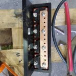
Too much ******** to connect to the negative stud of the shunt....
e1d5b8608c3974e5cb10e4d6142f4cff.jpg


Sent from my SM-G973U using Tapatalk
 

Forum statistics

Threads
188,383
Messages
2,906,455
Members
230,176
Latest member
Arcadia1415
Top