Solar Wiring question - gauge and connector type?

Martinjmpr

Wiffleball Batter
We have an inexpensive 100W "solar kit" (HQST) that we've been using on our camper for the past 4 years or so. It works well, the panel folds and goes into a nice little carrying case and we connect it to the battery (2 x 6v FLA golf cart batteries) on our trailer when we are camping without power.

One of the projects I've set myself to work on this year is to move my solar controller from its current position on the back of the solar panel up to a position closer to the battery. I'm planning on building a waterproof controller box to sit on the tongue of the trailer and I will then plug the solar panel directly into the controller, which will be permanently connected to the battery.

With my current setup (solar controller attached to the panel) there is a short set of heavy gauge, stiff wires connecting the panel's power output to the controller. Then, from the controller, I put a Battery Tender SAE harness on, and another SAE harness on the battery on the camper, and I connect the two with a 25' SAE "extension cable" that has SAE connectors on both sides. Having the 25' cable lets me position the panel so it gets the most possible sunlight exposure for the maximum charge to my batteries.

From what I can see, the SAE harness and extension cable are all 16 gauge.

In theory, a 100W panel at full power could produce as much as 8.3A (100W / 12v) but I presume that unless I'm sitting at the equator under a cloudless sky, I'm going to get less. Looking at the Wire Barn wire gauge calculator, it seems to me I'm already marginal in terms of my wiring gauge (according to this, even at a nominal power rating of 7A, I should be using 10AWG.)

My thought behind moving the controller is this: First of all, by having the controller close to the battery instead of 25' away, it should reduce power loss due to the length of the cable. This means more power to the battery and easier to keep the battery fully charged. Also, I could upgrade to a better quality MPPT charger instead of the cheap PWM charger that's on there now (which I think is limited to 20A.) Finally, although I have never had any issues despite having the panels and controller set up during a sudden rainstorm, my PWM controller is not technically rated as being "waterproof" so building a waterproof enclosure for the controller seems to be something that would be prudent.

With all that said, here are my questions for the group:

1. Assuming the distance from the controller to the battery is less than 2' (which it should be), a 16G or even 18G wire from the controller to the battery should be fine.
But what about from the panel to the controller? My panel originally came with some heavy gauge (and very stiff) cables with MC4 connectors. My understanding is that the panel itself puts out ~19v and that the controller "steps down" this power to a regulated ~14v output to the battery.

If I'm looking at these charts and calculators correctly, for a 19v output from the panel to the controller and ~25' of length, I'm going to need at least 12 or even 10g wiring, correct? Or have I miscalculated something?

2. Is there any reason to prefer the stiff (and difficult to store or work with) cabling that seems to come with solar panels over more pliable automotive wiring of the same wire gauge? And finally:

3. Is there any reason to prefer MC4 connectors over some other type of quick-disconnect connector? Seems to me an Anderson-type connector would work as well or better than MC4 but for whatever reason, MC4 seems to have become the "industry standard" for portable solar power packs.

Thanks in advance for any advice or recommendations!
 

john61ct

Adventurer
The SC needs to be right at the bank, panels farther away is OK.

For MPPT and great adjustability, monitoring, I reco Victron SmartSolar, smaller 75/15 model maybe $120 can handle up to ~250W or more

and when you want can replace the low voltage panel with 40+Voc and get 10-20% more output.

I would reco using Blue Sea's Circuit Wizard to calculate the gauge, use round trip measured distance and round up.

MC4 is fine if not disconnecting, otherwise Andersons are good.

Marine spec fine stranded tinned wire is best for outdoors, get the quality termination crimped properly or order custom from http://genuinedealz.com
 
For the actual amperage, most if not all solar panels will not see the actual rated power in the real world, if they do it is for a very short period of time in the coldest environment with the optimal direction facing the sun with no clouds. But if you want a real number and have a multimeter with an amp function you can hook it up and see what the amperage is coming through during peek hours to get a realistic number for wire sizing.

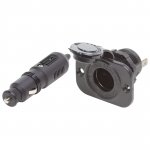
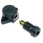
If 10 or 12 awg wires are required you can look into getting some extension cords as they are available in 10/3, 12/3, 12/2 bundled in a cable and fairly resilient for handling over bonded wire or single conductors. For connectors a standard cigarette lighter will handle that, there are also locking versions like Bluesea, or another option is a Hella style /din plug they are good for around 8 amps.

For stiff cables, its mostly due to the jacket material, usually cheaper pvc and the low standing count the conductor is made out of, most dc wires coming out of solar panels that I have come across are usually pliable with high strand count wires, but many will have a thicker insulation due to the high voltage requirements when they are connected in series, say 600-1000v


download.jpg download (1).jpg
 

vtsoundman

OverAnalyzer
Pretty simple power economics.

More voltage drop = more power drop = longer charge times....or larger panels.

Wire is cheap, panels and time are not.

Shoot for ~2% voltage drop at Isc...and call it bananas.

10/2 cord and 12/2 cord are cheap and good for about 25' at 6-8A for an 18V Voc panel.

Landscape/speaker wire works great. So do extension cords. Spend a little more and get decent jackets so it remains flexible.

All my portable panels are connected with #10 or #8...and I have the cables in 25' lengths.

It is surprising how little 75' can be if youre camping in a forest/meadow and need to top up...and it can be surprising how fast voltage drop adds up with distance.

Makes it easy to put the panels in the sun while charging (and keeps the vehicles in the shade).

Sent from my Pixel 4a using Tapatalk
 

Joe917

Explorer
There are two factors for sizing wire, amperage and voltage drop.
Wire should be sized to handle the maximum amperage the wire will carry. It does not matter if it is a 10" run or 10'.
Wire should be sized to keep voltage drop within required parameters. The longer the run the the more the drop, the thicker the wire the less the drop.
Keep the charge controller as close to the battery as possible to minimize voltage drop. You want the batteries to get the full output from the charge controller. Voltage drop between the panels and the charge controller is less important as long as the voltage is above the charge controller's requirement. For a small system there is very little advantage using MPPT over PMW.
 

john61ct

Adventurer
Stock ciggie ports are a dangerous abortion, terrible design.

Any of the other connectors mentioned are OK but not those.

Sent from my Nexus 6 using Tapatalk
 

PSea

Active member
1. move solar charger close to battery bank
2. get victron solar charger w bluetooth and battery temp sensing. can monitor all charge aspects fr smart phone
3. 60' 8awg flexible wire fr powerwerx. coils easily. I stow my wire in the solar panel suitcase.
4. I get EXCELLENT performance from my 110 w solar panel. 14v+ into the batteries. much better than original setup w crap solar charger on panel.
5 anderson plugs for connections. powerwerx.
 

Martinjmpr

Wiffleball Batter
Thanks for the input. I hadn't thought about using a heavy duty extension cord but that makes perfect sense!

Looking online it looks like most of the heavy gauge 120v AC extension cords are 10/3 rather than 10/2 (am I right that 10/2 means 2 circuits, positive and negative and 10/3 means 3 circuits, positive, negative and ground?)
 

rruff

Explorer
I didn't see anyone mention it but if you are using MPPT, then wire your panels in series so they'll be 24V instead of 12V.

P =V*I =I^2*R so, for the same power current drops to 1/2, which reduces power loss in the cable to 1/4. Or you could make the cable 1/4 the size (area) and have the same power loss. Or make the cable 4x as long and have the same loss... etc.

The battery controls the voltage at its terminals. The MPPT adjusts voltage and current from the source to achieve optimal power output.
 

vtsoundman

OverAnalyzer
Dealing with extension cords. Thats not exactly correct but you are on the right track.
10/2 means two insulated conductors within a common jacket. 10/3, three conductors and so on.
As far as cutting up to use ready made extension cords.
Thats right, you pretty much wont find anything two conductors bigger than 16AWG.
Said that, 10/2 & 12/2 is easily available as type SPT ’landscape cable’.
Which is really nice stuff to use on portable solar arrays and inexpensive compared to type SJ cable of extension cords or the jacketed cable for marine uses.

10/2 and 12/2 (like SOOW or similar) is available all over the place - just not at the home centers - a decent electrical supply house will have it (I picked up mine at Platt). I've also ordered it off of eBay and Amazon.

SPT landscape cable is also available...up to 8/2. Great stuff and really felxible.
 

rruff

Explorer
Wire is cheap, panels and time are not.
Shoot for ~2% voltage drop at Isc...and call it bananas.
It is surprising how little 75' can be if youre camping in a forest/meadow and need to top up...and it can be surprising how fast voltage drop adds up with distance.
Makes it easy to put the panels in the sun while charging (and keeps the vehicles in the shade).

I agree that sometimes a long cord is very handy. But... according to my calculations, a 75' cable with 10awg wire on a 100W 12W panel (MPPT controlled to 17V) will run at ~6A max, and give a power loss of 5.4W or 5.4%.

If you wire panels in series (or use a 24V panel to start with) and use a MPPT, you can cut that to 1.35W (or %) loss. Or use 16awg wire instead of 10awg if you are ok with a ~5% loss.
 

burleyman

Active member
I started with a used Renogy 100 watt suitcase panel for a camper trailer and moved the controller next to the batteries on the tongue. The controller is housed in a plastic, hinged binoculars case.

MC4 connectors do not have access for voltmeter test leads while connected. Anderson connectors do. For that reason, I cut off the originals and installed Andersons. That supposedly voids the solar panel warranty.

Extension cord power loss tests are easy with full sunlight and discharged batteries that want maximum solar amps. Have the panel, controller, and battery close to each other and start with the extension cord coiled or looped so that each end is within reach of the voltmeter’s test leads. Read charging amps from the controller, or use a dc ammeter. Meters need to read tenths for volts and amps.

Connect a voltmeter lead to each end of the positive wire from the panel to the controller and read the hopefully very small dc voltage. Do the same for the negative wire. Add the two small voltages together for total voltage loss. Multiply that summed voltage times the charging amps to determine panel watts lost (wasted) due to wire resistance.

Testing voltage on each end of a single current-carrying wire from the panel to controller, controller to battery (or any source to load), will show any voltage losses along that wire. Point-to- point voltage measurements on a single conductor/connectors rather than testing from positive to ground or positive to negative is seldom mentioned.

On a van, I have rooftop and portable panels. I never realized how difficult it would be to obtain continuous full sun until dabbling in solar. I have numerous extensions, from 16 to 12 gauge wire crammed everywhere. Even with long lengths of 14 awg, power loss is minimal for a 100 watt panel and acceptable per the above tests, versus very little charging if even partially shaded.

Another quick and dirty test is to try two different sized, equal length extension wires, and see if charging amps change. What vtsoundman said about landscape wire. My favorite.
 

Rando

Explorer
This is probably too late - but as your charge controller is of the PWM variety, there is no issue with voltage drop between the panels and the charge controller. The system is already dropping the 17-19V from the panels down to 13-14V charge voltage for the batteries, so as long as you are losing less than 2-3V in your wires, there is no power to be lost by using the 16AWG wires you already have. The wire voltage drop tables are not the correct tool in this situation (because you don't care about limiting voltage drop to 3 or even 10%). The only caveat is that you do want to stay below the ampacity of the wire. Here is a useful table:
From PKYS
Ampacity-Table.png
 

OllieChristopher

Well-known member
This is probably too late - but as your charge controller is of the PWM variety, there is no issue with voltage drop between the panels and the charge controller. The system is already dropping the 17-19V from the panels down to 13-14V charge voltage for the batteries, so as long as you are losing less than 2-3V in your wires, there is no power to be lost by using the 16AWG wires you already have.

That is very interesting and something I have not considered. It's easy to forget how many volts some of these solar panels pump out. Even with an MPPT charge controller a few volts drop would not be a big deal. As long as the wires can handle the amps then sizing down wires is very doable.

Thank you Rando!! That is a very good tip when working with solar panels. This technology is evolving so quickly it is easy to not realize we have to change and adjust the way we think when working with solar power.

You should get the Expedition Portal of the month award for that post!! (y)
 

Rando

Explorer
Unfortunately, with MPPT the voltage drop does matter. MPPT is essentially converting that 'extra' voltage that is lost in a PWM system into usable power. So if you have a 10% voltage drop in your wires, you are loosing 10% of the power from the panels.

In general there is a tendency for folks to regurgitate 'rules of thumb' without thinking about if the rule applies to the particular situation. In this case the 'rule' does not apply.
 

Forum statistics

Threads
188,495
Messages
2,905,718
Members
230,501
Latest member
Sophia Lopez
Top