You are using an out of date browser. It may not display this or other websites correctly.
You should upgrade or use an alternative browser.
You should upgrade or use an alternative browser.
The Rolling Restoration & Customization Of My 88' Range Rover Classic
- Thread starter rrclassicbt550
- Start date
zenithj
Ken
I am looking into relocating my ECU as well since I am planning on lowering the passenger side seat too. I haven't given it too much thought right now, I guess I will cross that bridge when I get there.
I know where Green Oval Motors is, their great! They are who I go to when my Rover is broken beyond my skill level. I was planning on stopping by there before I head out on my road trip at the end of July. Maybe you can see it then? Do you work there?
I do ... I am the Service Manager at Green Oval. Doug is the owner. I am curious ...... How much quicker do you think the second 'seat lowering' project might be if you were to do it again?
Snagger
Explorer
Don't you just love customer feed back like that! Shame it's not the norm in the UK - most customers are very dis-satisfied with garages. Unlike the US, home building/maintenance and car repair/servicing "professionals" don't need to be qualified, licensed or even registered (electricians and gas workers excepted), which is why both professions are so full of crooks and cowboys...
rrclassicbt550
Farmer Jon
The epic saga is finally over!
The epic saga that has been the lowering of my driver’s seat is finally over! I can now see perfectly through the middle of the windscreen, but I have to say that it would have been so much easier to do two inches; that extra inch down really made things difficult from a metalworking standpoint. I finished it up yesterday and now all that is left is for me to do is grind down the welds. I will get some better pictures so there is a good “before and after” look at things for everyone to see. I am not sure I want to really think about how many hours that took but I would bet it was somewhere in the neighborhood of sixty hours from the initial strip down of the interior to the finishing of the drivers’ side. One interesting thing I overlooked was; after I finished everything and moved on to setting up the placement of the backseat. I decided to sit down in the back seat to make sure there is enough legroom (which there is), but since the drivers’ side seat is now an inch and a half off of the floor of the vehicle, the rear foot room has been reduced. Fortunately, the reduced foot room is only noticeable when the driver’s seat is all the way back which it hardly ever is. Other than that I have to say that these modifications are working out even better than I thought they would and I am looking forward to finishing everything up.
I am currently working on the mounting structure of the rear bucket seats and the drawer system because my time frame for leaving is coming up pretty quickly and I want to make sure that I get everything else that needs to be finished done before I lower the passenger side seat. Even though I am only going to lower the passenger side two inches, I think it will still probably take twenty hours to do and I am not sure I can spare that amount of time with the mountain of other things I have to do at this point; I will definitely do my best to get it done before I leave though.
I am posting the pictures I have of the drivers’ side seat installed, the rear seat location, welding up random holes Land Rover left in the floor and the progress of the rear seat mounting structure. If you have any questions or want specific pictures, please let me know and I will try to get back to you as soon as I can. Like I said though, I will take the drivers’ side seat out and take some “after” pictures of the seat mounts as well as more progress pictures of the rear seats.
rrclassicbt550
Farmer Jon
And the rear seat structures progress...


rrclassicbt550
Farmer Jon
Did you consider to install a smaller steering wheel instead the tilt-able steering column?
That is a good point, that might have been a good alternative before I lowered the seat. After sitting in the Rover with the seat finished and its permanent lowered location, I think that the stock angle of the steering column would feel pretty weird so I am going to give it a go with the tilt column. I wish I had given the smaller steering wheel a try during the three years I owned my Rover before this round of modifications, might have been more comfortable.
rrclassicbt550
Farmer Jon
I do ... I am the Service Manager at Green Oval. Doug is the owner. I am curious ...... How much quicker do you think the second 'seat lowering' project might be if you were to do it again?
Hmm...if I were to do it all a second time, I would only go two inches down instead of three. To go down two inches would probably take me around twenty hours for each side. However, if I had to do three inches down again, it would easily be thirty hours and probably more toward forty hours. That extra inch was a major pain...I am glad I finished it, but I am not sure it was worth double the amount of time for one extra inch when I could just slouch a little.
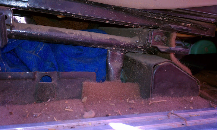
For the passenger side two inches is the most it could go down, the linkage for the transfer case and transfer case mounted drum brake with its linkage, would get in the way if it were to be lowered any further than that. Plus, if the passenger side seat were to be lowered more than two inches, a new location for the ECU would have to be found as well.
rrclassicbt550
Farmer Jon
Don't you just love customer feed back like that! Shame it's not the norm in the UK - most customers are very dis-satisfied with garages. Unlike the US, home building/maintenance and car repair/servicing "professionals" don't need to be qualified, licensed or even registered (electricians and gas workers excepted), which is why both professions are so full of crooks and cowboys...
I learn something new everyday! Thank you, I will definitely be keeping that in mind when I go over to the UK in the future.
Series1Rangie
Adventurer
Jon,
That is a tremendous amount or work. WOW good on ya. I will be out in the garage this weekend, and will snag a picture of the seat mount lowered from a Disco manual seat.
Cheers,
Mike and Myles
That is a tremendous amount or work. WOW good on ya. I will be out in the garage this weekend, and will snag a picture of the seat mount lowered from a Disco manual seat.
Cheers,
Mike and Myles
Series1Rangie
Adventurer
Sorry it took so long.
So here are some (cell phone) pictures of the modified Discovery manual seat bases. It was easier because the manual seat base in a Discovery is a couple of bent tubes attached to a flat base. Where the tubes attach to the base there is a c shaped bracket that the tubes were slotted into and then welded. We drilled out the spot welds and then removed ~2.5 inches from the vertical section of the tube, put the tube into the seat base, bent the c bracket around the tube, and welded it. When mounting the seats in the classic, I put stiffeners under the floor plan to keep the everything from flexing and to prevent pull through. I think the seats only had 4 bolts holding them into the Discovery, I put a couple more in cause I could.")
You can see below that there is extra metal on the bracket that was folded over, I cannot remember for the life of me why we had extra there.


We had to notch the stiffener to accommodate one corner of the tube (inside rear) at this height.
If I was to modify another set, I wouldn't come down quite so low, and probably not back so far. When the seat is all the way back, I have a few inches between the pedals and my feet, and I am 6'3 and a little, most of that is torso, so it might be good for a long legged person. I have at least 6" between my head and my non-sunroof roof (with headliner) The other reason, I might not go so low, is that it makes it hard for anyone under 6'1? to see over the hood. My fiance is 5'9" and feels like she is seeing mostly hood and steering wheel when she drives it. I am a big fan of sit upright have good control of the wheel and good visibility, but I am not sure how I would add an inch safely and simply. I will probably go to (gasp) jeep tj seats so that I have a flip and tumble being a 2dr.
Cheers, and again nice progress.
Mike and Myles
So here are some (cell phone) pictures of the modified Discovery manual seat bases. It was easier because the manual seat base in a Discovery is a couple of bent tubes attached to a flat base. Where the tubes attach to the base there is a c shaped bracket that the tubes were slotted into and then welded. We drilled out the spot welds and then removed ~2.5 inches from the vertical section of the tube, put the tube into the seat base, bent the c bracket around the tube, and welded it. When mounting the seats in the classic, I put stiffeners under the floor plan to keep the everything from flexing and to prevent pull through. I think the seats only had 4 bolts holding them into the Discovery, I put a couple more in cause I could.
You can see below that there is extra metal on the bracket that was folded over, I cannot remember for the life of me why we had extra there.
We had to notch the stiffener to accommodate one corner of the tube (inside rear) at this height.
If I was to modify another set, I wouldn't come down quite so low, and probably not back so far. When the seat is all the way back, I have a few inches between the pedals and my feet, and I am 6'3 and a little, most of that is torso, so it might be good for a long legged person. I have at least 6" between my head and my non-sunroof roof (with headliner) The other reason, I might not go so low, is that it makes it hard for anyone under 6'1? to see over the hood. My fiance is 5'9" and feels like she is seeing mostly hood and steering wheel when she drives it. I am a big fan of sit upright have good control of the wheel and good visibility, but I am not sure how I would add an inch safely and simply. I will probably go to (gasp) jeep tj seats so that I have a flip and tumble being a 2dr.
Cheers, and again nice progress.
Mike and Myles
rrclassicbt550
Farmer Jon
So here are some (cell phone) pictures of the modified Discovery manual seat bases. It was easier because the manual seat base in a Discovery is a couple of bent tubes attached to a flat base. Where the tubes attach to the base there is a c shaped bracket that the tubes were slotted into and then welded. We drilled out the spot welds and then removed ~2.5 inches from the vertical section of the tube, put the tube into the seat base, bent the c bracket around the tube, and welded it. When mounting the seats in the classic, I put stiffeners under the floor plan to keep the everything from flexing and to prevent pull through. I think the seats only had 4 bolts holding them into the Discovery, I put a couple more in cause I could.
You can see below that there is extra metal on the bracket that was folded over, I cannot remember for the life of me why we had extra there.
We had to notch the stiffener to accommodate one corner of the tube (inside rear) at this height.
If I was to modify another set, I wouldn't come down quite so low, and probably not back so far. When the seat is all the way back, I have a few inches between the pedals and my feet, and I am 6'3 and a little, most of that is torso, so it might be good for a long legged person. I have at least 6" between my head and my non-sunroof roof (with headliner) The other reason, I might not go so low, is that it makes it hard for anyone under 6'1? to see over the hood. My fiance is 5'9" and feels like she is seeing mostly hood and steering wheel when she drives it. I am a big fan of sit upright have good control of the wheel and good visibility, but I am not sure how I would add an inch safely and simply. I will probably go to (gasp) jeep tj seats so that I have a flip and tumble being a 2dr.
Cheers, and again nice progress.
Mike and Myles
Now now don't be too hasty, lets try minimizing the amount of Jeep parts that go into Land Rovers. ; ) In the past (before I saw the light and bought a Land Rover), I used to love and own Jeeps; one of which was a Jeep Yj. In the YJ, the seat riser mechanism on the passenger side was where the flip and tumble feature actually functioned; the seats had nothing to do with it. So if you "have to" put jeep parts into a Land Rover just put in the passenger side seat riser and stay the heck away from the seats.
Besides the fact that Jeep seats are uncomfortable, they wear out too fast. Mine actually gave me a lower back injury due to a "not very well thought out" bar that runs across lumbar area of the seat. When the padding of the lumbar area wore out, that bar was conveniently located in just the right place to repeatedly hit one of the vertebrae in the lower part of my spine every single time the vehicle went over any kind of bump (which if you have ever taken a lifted Jeep for a spin, it can be VERY BUMPY).
One day when I got out of the Jeep and fell onto my hand and knees because my back hurt so badly my legs wouldn't work, I decided to replace the seats with Corbeau's (so that it wouldn't happen to someone else) and sell the Jeep. So if you value a comfortable ride or your personal health, put as few Jeep parts in your Land Rover as possible but definitely stay away from the seats.
Good job on those Discovery mounts! They look so much easier to modify compared to the Range Rover mounts...lol. Why don't you just buy another set of drivers side Disco mounts not lower them as much and then buy a set of Jeep passenger side mounts and see if you have better success?
Series1Rangie
Adventurer
In the YJ, the seat riser mechanism on the passenger side was where the flip and tumble feature actually functioned; the seats had nothing to do with it. So if you "have to" put jeep parts into a Land Rover just put in the passenger side seat riser and stay the heck away from the seats.
I have a set of early brackets (both sides with flip and tuble) that I have been working on modifing for my seats. Not sure its the best option, and to be honest, I hate the Disco seats. horrible to sit in for long highway stretches, not great off-road, but I typically don't notice as much.
Good job on those Discovery mounts! They look so much easier to modify compared to the Range Rover mounts...lol. Why don't you just buy another set of drivers side Disco mounts not lower them as much and then buy a set of Jeep passenger side mounts and see if you have better success?
It must be my simple/lazy side, but i want easy access from the drivers side. right now I open the rear window (slider) and get access that way.

Hi-jack off
How is the progress coming. you are slated to leave in August yes?
rrclassicbt550
Farmer Jon
Status update..
I am sorry it has been a while since my last update but it always seems that when I have a deadline looming everyone and their grandmother either needs a favor from me or has some sort of event that I have to attend (i.e. birthday parties, bachelor parties, weddings, etc.) so I have only been able to do a couple of things on the Rover since my last update. Thankfully, today and tonight are open for me to me to get some work done and after the two birthday parties this week and my buddies wedding this weekend it looks like my schedule will clear up enough that I can really get down to business on the Rover.
Anyway, so the progress as it stands on the Rover right now. The driver’s side seat mounts are done, just waiting to be painted, but I will paint them when I patch the floors and paint/sound deaden the entire floor sometime early next week.
The rear seat structure is almost done, it would be done by now, but conveniently I ran out of welding gas and welding wire at the exact same time; combine that with my lack of time to buy more and further progress has come to a screeching halt for the last few days. I am buying more welding gas and wire today so that I can finish what is left of the welding on the rear seat structure tonight.
I did manage to fit the strip down and modifications of the 1995 RRC steering column in earlier this week. So now all that is left to do on that is wire it in and either fabricate a mount or find an original 1995 RRC steering column mount to fit it into the Rover.
Now for the info:
The rear seat structure has been very easy to do, especially when compared to the saga of lowering the front seat. It took me longer to figure out how to do it and then layout all the measurements than it has to actually fabricate the seat frame. If I didn’t run out of welding gas and wire I would say that the bulk of the work on the structure could be knocked out in a weekend. I think I have maybe five or six hours into the rear seat structure so far; which includes the design of it.
Maybe this is like “the calm before the storm” and things will become more difficult later on, but I was really expecting this to be much more difficult than it has been so far; its just been cutting, welding, and drilling. haha I guess that is why I haven’t taken too many pictures…it is sort of a “what you see is what you get” kind of a thing.
I laid out the rear seat structure the way I did partly because I had to and partly because I wanted it to be that way. By luck it would seem that all the floor supports and mountings somehow are in just the right place to tie in perfectly.
Let me explain. An original Range Rover Classic seat base/seat tracks have measurements of 12.5” front to back x 17.5” side to side. And whether by luck or by the “careful” planning of Land Rover, the distance from the front mounting structure for the original 60/40 rear bench seats to a floor support that runs the width between the wheel wells is roughly 12.5”. The benefits of having a floor support in that particular location means that I can tie the structure I am making into it instead of having to fabricate one of my own.
For those of you who don’t know, it is not really a safe idea to just drill some holes in a sheet metal floor and then through-bolt the seat frame directly to it, because in a car accident the seat could just tear through the sheet metal floor leaving the person sitting in that seat in a very bad and potentially dangerous situation. So when mounting a seat into a vehicle, always try to tie into as much structure as possible; especially when the seat belt mounts directly to the seat itself on both sides.
I am a big believer in looking at “overkill” as a good place to start. So I decided to tie into the original seat belt mounting holes as well, because those seat belt mounts are tied into mountings on the frame.
I am using 2” x .250” flat steel for everything but the leading edge of the rear seat structure, which is 1.5” x .250” flat steel.
So to recap, I am attaching the fabricated seat structure to the Rover in twelve locations that are located on three floor supports, one of which is tied directly into the frame. I am using zinc plated grade 8 bolts, washers, and nylock nuts for everything; and I might also beef up the original mountings as well.
rrclassicbt550
Farmer Jon
And a visual aid for the seat measurements...

rrclassicbt550
Farmer Jon
Steering column modifications...
So I am posting pictures of the modifications I did to the 1995 RRC steering column as well as some pictures of the strip down of the column.
When the idea of putting tilt wheel in 1988 RRC originally popped into my head I thought I could just use the tilt wheel out of a 1995 RRC. Later on I found out the actual range of tilt on a 1995 RRC steering column was something in the neighborhood of .750” or ¾” which is pathetic to say the least. However, I was not going to let that get in my way so I sourced and bought the steering column out of a 95’ anyway.
When it arrive I immediately started investigating why the range of travel was so pathetic. It turns out that because it was the first year that Land Rover had ever installed an airbag in an RRC, they decided to restrict the range of travel to make sure the alignment of the airbag to the driver was optimal.
I do not have a 95’ RRC, I have an 88’ RRC and therefore do not have any of the airbag sensors or wiring and I am not required to have an airbag in it; not to mention my seat is now three inches lower than stock so the alignment would be way off anyway. Given these reasons, I decided to modify the steering column to free up a little more range of travel in the tilt function.
Here is how I did it:
I stripped it all down, which proved to be quite interesting. I learned not only how the basic strip down goes but I also learned a lot about how the tilt function works and I learned that the 95’ steering column has an added safety feature; the column itself is designed to collapse about 6” in a car accident. I posted some pictures showing the telescoping shaft and the housing of the column.
There are three locations where the range of travel is restricted; the two sides and the bottom. There are two bolts that go through the sides, which are restricted by the size of the two (lets call them “windows”) windows they pass through. The third restriction is where the tilt gear hits the actual structure of the column itself.
To open up the range of travel the steering column has I first machined out the two side windows. I opened up the windows to a total measurement of 1.100”. I machined out .400” at the top of the windows (which restricts the “tilt down” function) and the bottom of the windows by just over .100” (which restricts the “tilt up” function). I then machined out .300” of material where the tilt gear hit the structure of the column, which was by far the easiest of the machining.
The machine work was complicated a little bit by the fact that I was not able to find a way to disassemble the uppermost portion of the steering column; so I had to tape it off to protect it from getting metal shavings in any of the rotational surfaces of the steering shaft.
Nevertheless, when all was said and done, and the column was reassembled; the range of travel was greatly increased. The range of travel for the tilt function had previously been around .750” but now is able to move over 2.5”, which is comparable to most modern day vehicles.
Similar threads
- Replies
- 4
- Views
- 681
- Replies
- 4
- Views
- 2K
- Replies
- 2
- Views
- 1K
- Replies
- 0
- Views
- 168