Troubleshooting Renogy 20A DC-DC converter?

Martinjmpr

Wiffleball Batter
OK this is a sequel to my previous thread posted here: https://forum.expeditionportal.com/threads/dc-dc-charger-as-an-alternative-to-generator.246276/

I appreciate all the help I got in that thread especially from Dave in AZ

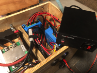
I'm now zeroing in on one specific component of my system, the Renogy 20A DC-DC charger. I put this in almost 5 years ago, to keep a little "power box" charged up. I made the "power box" from a Trolling Motor battery case and a 90AH FLA (wet) battery. https://forum.expeditionportal.com/threads/installing-renogy-dc-dc-charger-in-2018-f-150.214386/

Anyway, I've now upgraded that FLA to a 100AH LiFePo battery. But I seem to be having issues with the charger.

The LiFePo battery has a very cool Bluetooth system that displays battery statistics (with the old one I had to "guess" the charge level based on the voltage.)

First time I hooked up the DC-DC charger to the battery I got this as the display:
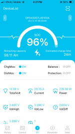
2025-01-01 16.21.10.png

Notice the Current display (top row center): 20.35A going into the battery. I was stoked! My system was working and working great! This was at 16:21.

But just 7 minutes later, THIS was the display:
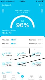
2025-01-01 16.28.07.jpg

Current showing as "zero." Keep in mind I have changed absolutely NOTHING in the 7 minutes, I think I may have cycled the ignition on the truck on and off, but that's it.

The DC-DC charger is working (green pilot light on.) At this point DIP switch SW5 was in the "on" position (for a Lead-Acid battery.)

The next thing I did was switch the SW5 switch to "off" which, per the manual, is the proper setting for a LiFePo battery.
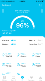
2025-01-01 16.29.27.png

No luck. I have to emphasize that the DC-DC charger appears to be working (that is, it powers on.) There are no fault codes (which would be indicated by a red light on the charger.)

Before anyone asks, yes the engine was running.

Just to double check, I measured voltage going in and coming out of the charger.

Voltage going in was 14.45

But voltage going out was only 12.80.

I consulted the manual and set the DIP switches for a LiFePo battery charging at 14.4v. Settings were:

SW1 ON
SW2 ON
SW3 OFF
SW4 ON
SW5 OFF

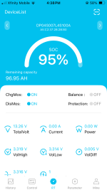
Pulled up the app again and still no charging to the battery:
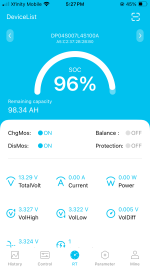
2025-01-01 17.27.22.png

Note that this was after about 45 minutes of driving around with the battery connected to the charger.

So I'm kind of at my wit's end here and I'd like to get any input from someone who might have an idea what is going on?

Several possibilities have occurred to me:

1. Maybe the battery IS charging but the bluetooth BMS isn't picking it up. That doesn't seem likely since the measured voltage at the output of the charger is only 12.80 and the fully charged battery is at a voltage of over 13v per the BMS.

2. Maybe there is some kind of "sensing logic" in the DC-DC converter that is telling the converter "this battery is over 13v therefore charging is not needed" and the charging function is turned off. I've ready the (awful, really horrible) manual front to back and if this happens it doesn't say so anywhere I can find. Also this doesn't explain why, when I FIRST hooked it up and the battery was at 96%, it DID show it charging at 20.35A.

3. Maybe the charger is just defective? It has been sitting in the back of the truck since early 2020. It's been bounced around (although it sits under the seat and there is a piece of carpet underneath it that provides a little padding.) Perhaps it got damaged somehow? The only way to know this for sure, I think, would be to swap in a "known good" charger and see if there is any different result

As I said in the other thread, I'm pretty sure I have the DIP switches in the correct setting and there are literally no other settings on the charger that I'm aware of.

Any other thoughts on what might be causing this? As of right now it's looking like a defective charger but I can't help but wonder if there is something else going on. I'm specifically wondering why the charger is only putting out 12.8v when there are 14.4 going in.

In the previous thread it was mentioned that the 8AWG cable connecting the DC-DC charger to the battery was inadequate and I should have used 6AWG. I understand that but at least initially I WAS getting 20.35A to the battery, so I'm not sure this is it.

Final question, am I right in thinking that once the battery voltage (on the power box) drops below 12.8v, it should start charging if there are 12.8v going in?

Anyway, I'm trying to get this figured out since we leave in a week for another long trip. Fortunately because it's cold this is not going to be very taxing on the refrigerator that is powered by the battery box and we will have electric hookups so if needed I can charge the box from a 120v AC power source.

Thanks for any input!
 

Dave in AZ

Well-known member
1. After resetting dip swutches, a lot of devices need to be completely powered iff to see the reset and change their config. The 12.8v looks like a lead acid float voltage. Remove all power from dcdc from both sides, set dip5 to lithium setting, add battery power back. See if that helps.
2. The 96% soc display is completely bogus if you just hooked it up, based on voltage that is +- 20% accurate on a snapshot like that. You need to drain battery to empty, then recharge to full, to reset bms charge display for any accuracy usually.
3. LFP battery may be completely full, not 96%. Many LFP will go into a resting state after full, and show 13.2 to 13.3V on their bms. You need to use that battery and drain it down 50%, then retry. See if it will charge then. I would just drain it to 0% til it shuts off, then recharge, for bms monitor reset.
 

burleyman

Active member
TL/DR: Try direct connection charging. Remove the wires from the DC-DC, connect them together, then look at bluetooth screen.

I’ve been following along as my situation is similar. After my seven-year old 100ah AGM decayed, and lifepo4 prices decreased, I took the plunge. I’ve been using the old continuous duty relay, connected directly to the house battery. I also monitor charging volts and amps while driving. Turn on and off as needed with a toggle switch.

After lots of reading and listening, I now have two Elefast 100ah lifepo4’s to charge. I want to charge at about the recommended 20 amps while driving (alt), but yet be able to charge at 50 amps or so when occasionally wanting a fast charge. After reading lots of DC-DC charger headaches, I decided to experiment with direct connection.

With one lifepo4 directly connected via 12 feet long #10 awg wires, at 14.4vdc, the charging remains fairly steady with amps in the mid 20’s while driving. For me, that problem seems solved by direct charging. That is why the mention in the other thread about removing the charging wires from the DC-DC and connecting them together to remove the DC-DC as a problem. In my case, no purchase price, installation, or replacement. Yes, watts may be wasted, but I don’t care as long as the amps are there and the alternator can handle it.

I do care when trying to squeeze the most out of solar panels. Different situation.

Picture below. #16 ga wire, 20 feet long, directly connected from starter battery to lifepo4. 14.4v, 5.88 amps into the battery. Larger wires, more amps.

The next problem, how to fast charge from a 120vac source. If from a noisy generator, shortest run times possible. Same if wanting a fast charge from the alternator while idling.

For years I’ve used 30 amp, thirty dollar Chinese power supplies. You have to install your own wires. Adjust the voltage to output about 25 amps. They are not made to output rated amps continuously. Using one on my lifepo4 showed no charging until the mid-thirteen volts, and very finicky about voltage adjustments to prevent overcurrent and damaging the power supply.

I took the plunge on a 65 dollar 100 amp Chinese power supply. I was surprised to discover it had two potentiometers to adjust both voltage and current. Constant voltage, constant current. It only showed one adjustment for voltage on the Amazon ad. It helps to have a trim pot tool to adjust the tiny things.

Fairly simple. Do not connect it to the battery. Turn it on. Adjust the voltage to whatever charging recommended. Next, connect to the battery. Adjust the output charging current to what you want.

It is derated if powered by 120v instead of 240vac. It is also derated further for continuous use.

Don’t get hung up on voltage seen after connecting. It may seem low. Concentrate on amps instead. For me, the amps remained constant, even into 100% SOC, then tapers off until BMS shutdown. As it tapers off, the voltage seen will slowly rise.

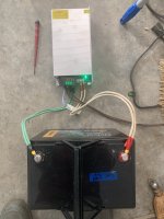
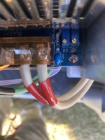
Picture below shows power supply using parallel 10awg wires. I ran it for a few minutes at 70 amps, and adjusted to 50. After adjusting, it now seems plug and go.

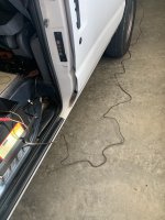
With an inverter connected to the battery up front, and an extension cord to the charger at the rear, it charges.

I’ve not connected to the gas, supposedly quiet inverter generator yet.

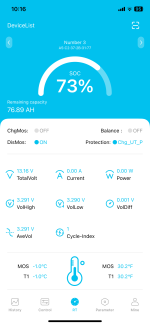
Screen shot shows battery below freezing. Input Charging MOS Off, Output on. Wouldn’t charge. Check.

Later, direct sunlight, battery at 40F, Input back on. Check.

So far, so good.
 

Attachments

  • IMG_6665.png
    IMG_6665.png
    117.3 KB · Views: 7
  • IMG_6649.jpeg
    IMG_6649.jpeg
    1.6 MB · Views: 7
  • IMG_6662.jpeg
    IMG_6662.jpeg
    1.4 MB · Views: 7
  • IMG_6658 2.jpeg
    IMG_6658 2.jpeg
    1.8 MB · Views: 7

DaveInDenver

Middle Income Semi-Redneck
I consulted the manual and set the DIP switches for a LiFePo battery charging at 14.4v. Settings were:

SW1 ON
SW2 ON
SW3 OFF
SW4 ON
SW5 OFF

If this is the correct manual:

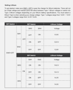
The DIP switches seem wrong. If I read the chart right to get 14.6V you would have

SW1 = ON
SW2 = ON
SW3 = ON
SW4 = ON
SW5 = OFF

Screenshot 2025-01-04 at 15.37.09.png

If I was to hazard a guess the controller could be confused by your selection.

It expects SW1 and SW2 to both be OFF to select the lower voltage range OR both SW3 and SW4 to be ON to select the higher range.

As for the 12.8V output. That's probably not actually the output but rather the battery voltage. The generally best practice with lithium is to NOT float.

So if the charger isn't getting into a valid charging state it is just in an idle open circuit, no output, and just following the battery voltage to sense state of charge. It may eventually restart charging but that will depend on what the logic tells it to do.

I'd think 12.8V would be detected as a very nearly full discharge for LiFePO4 and it would drop back into bulk. But it may also have a timer that has to run down or a lock-out feature based on the input voltage (e.g. it might not like being ignition cycled too quickly).

FWIW, I would not use 14.6V, that's 3.65V per cell, which is where many BMS will trigger an over voltage fault. You don't really gain that much going beyond 3.4V per cell while charging. But to allow for tolerance and to give a balancer time to work while charging a target more like 3.55/cell (around 14.2V for a 12V system) or so is safe while returning very, very close to 100% of the energy back.

It doesn't look like you got anywhere near there from what the BMS is reporting. Just something to think about.
 
Last edited:

Martinjmpr

Wiffleball Batter
If this is the correct manual:

The DIP switches seem wrong. If I read the chart right to get 14.6V you would have

SW1 = ON
SW2 = ON
SW3 = ON
SW4 = ON
SW5 = OFF

View attachment 865159

If I was to hazard a guess the controller could be confused by your selection.

It expects SW1 and SW2 to both be OFF to select the lower voltage range OR both SW3 and SW4 to be ON to select the higher range.

As for the 12.8V output. That's probably not actually the output but rather the battery voltage. The generally best practice with lithium is to NOT float.

So if the charger isn't getting into a valid charging state it is just in an idle open circuit, no output, and just following the battery voltage to sense state of charge. It may eventually restart charging but that will depend on what the logic tells it to do.

I'd think 12.8V would be detected as a very nearly full discharge for LiFePO4 and it would drop back into bulk. But it may also have a timer that has to run down or a lock-out feature based on the input voltage (e.g. it might not like being ignition cycled too quickly).

FWIW, I would not use 14.6V, that's 3.65V per cell, which is where many BMS will trigger an over voltage fault. You don't really gain that much going beyond 3.4V per cell while charging. But to allow for tolerance and to give a balancer time to work while charging a target more like 3.55/cell (around 14.2V for a 12V system) or so is safe while returning very, very close to 100% of the energy back.

It doesn't look like you got anywhere near there from what the BMS is reporting. Just something to think about.


Dave, My Man! You figured it out!

It doesn't help that my manual doesn't have that extra page that you have. Took me a few read-throughs but I finally got it.

I blame the technical writers at Renogy for that. I've seen people on other forums complain about the less-than-adequate instruction manuals.

So per that manual I set the dip switches to OFF ON ON ON OFF.

That is, SW5 OFF is for LiFePo battery.

Then SW3 ON and SW4 ON = Type II Lithium battery

And finally SW1 OFF and SW2 ON = 14.4v Charging voltage.

Made the switch, plugged in the battery and this was the result:

BEFORE starting the truck (DC-DC charger OFF):

2025-01-04 16.38.40.png

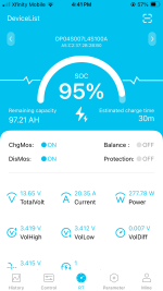
And AFTER starting the truck (DC-DC charger ON):

2025-01-04 16.41.04.png


Showing 20.35A charging. YaY!

Of course, I'd gotten to that point before, but then as soon as I cycled the engine off (long enough for the DC-DC charger to switch off) and back on again, I was back to zero charging.

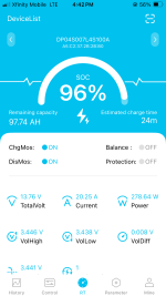
So I shut off the truck for a minute or so, then started it up again.

Success!

2025-01-04 16.42.48.png


So, suffice it to say the DC-DC charger is working as it should be. At least for now.

I still have it hooked up in the truck. So tomorrow I'll drive around a bit and keep monitoring it so I can make sure it's still working.
 

Martinjmpr

Wiffleball Batter
For those that followed my other thread, one of the things I was looking to do was to see if I could charge the TRAILER batteries using the 20A DC-DC charger.

I made a 20' long cable from 8AWG wire and two Anderson connectors. The idea being that if I put an Anderson on my trailer batteries, I could simply plug it into the DC-DC charger and charge the trailer batteries without a generator.

So, I plugged my 20' cable into the DC-DC charger and then plugged it back into the same LiFePo battery and looked at the display.

2025-01-04 16.45.44.png

Interesting, eh? It's the EXACT SAME configuration as above - EXCEPT it's running through an 8AWG cable.

Amperage dropped by HALF! Actually a little over half from 20.35 to 9.83. Since my Trailer battery bank has two x 100AH batteries, that means the most power I can put to each battery is a little over 4A.

Heck, I can get better than 4A on a sunny day with a solar panel!

HOWEVER, I haven't given up on coming up with a creative idea to keep the batteries charged without a generator.

My next idea would be to look at either having a 40A DC-DC charger that connects to the truck battery via alligator clips, and then goes straight to the trailer batteries (option 1), OR get a 1000W inverter, again, attached to the truck battery via alligator clips, then plug in the 120vAC lithium-specific charger I have and use that (Option 2).

Option 2 seems "redneck as hell" to me: Take 12v, convert it to 120vAC then convert it BACK to 14.5v for charging?

But as we used to say in the Army, "If it's stupid but it works, it isn't stupid." I carry the 120vAC charger with me anyway in case I need to recharge a battery so either way is going to add one equipment case to my load out.
 

DaveInDenver

Middle Income Semi-Redneck
@Martinjmpr, to your second issue with the lower charging current. What's the alternator end voltage and what's the voltage at the charger input?

This is probably just simple loss in the cable. You'll see voltage drop with a run that long and there's nothing you can do about that other than larger cable.

The DC-DC charger will convert all the power it has available at it's input, which in this case will be reconstructed as the higher voltage with reduced current.

In simple terms (meaning no other losses), say you start at 14.6V @ 20A and have 2V of drop in the cable the input of the DC-DC will be 12.6V @ 20A, which means of the 292 watts you started with the charger only has 252 watts to work with. When it transforms this power back to charging voltage of 14.6V the new current will be 17.25 amps. In reality there's internal efficiencies that mean to get 20A of charging current at 14.6V (theoretical perfect 292 watts) you will have to start with 5% to 10% more input power (so perhaps 320 watts input for 292 watts charging).

The difference in power between the alternator and charger is lost in heating the long run of cables. This isn't necessarily dangerous as long the heating isn't so excessive as to cause the cables to melt their insulation but it is irritating.

I wouldn't have thought a 40 foot (remember out and back) run of 8 AWG would see quite this much loss but maybe when you account for connections and plugs. I'd expect more like maybe a volt drop at ~20A, so you'd be seeing perhaps 10% loss or there about.

Another possibility is you're triggering the low input voltage on the DC-DC, where it thinks the engine isn't running and turning off. They can sometimes get into a cycle where it's confused thinking the engine is starting and stopping.

How likely this might be depends on how small of a window of voltages. My Toyota alternator tends to run pretty low once it's settled, 13.6V or so. Which doesn't give a lot of margin if a DC-DC was to think 13.0V is " engine off" and there is 0.5V of drop.

Depending on how fast this cycle occurs you may see an averaging. Say the charger can do 200 watts but it's cycling on for 30 seconds, off for 30 seconds. The battery will in effect only get an average of 100 watts over time.

Using ignition sense is the best way to solve this but if the option exists to adjust settings then lowering the engine off voltage can work to keep the charger on, too. Going to maybe around 12.7V as a turn-off shouldn't risk having the charger run flat the starting battery but might be enough to keep the charger on.

This is a pretty specific issue with more "maybes" that have to line up. More likely is just simple loss and voltage drop.

Oh, yeah, I also glossed over that 9A may be completely legitimate if the battery is already mostly charged. The charger may be tapering current thinking the aborption stage is finishing.

To test this you really shouldn't be trying to start a charge on a fully charged LiFePO4. Drain it down some, maybe 80% SOC, and see what happens.

Ignore what the fuel gauge says at 96%. An open circuit 13.6V or >3.4V per cell is considered 100% SOC. Lithium cells don't regulate themselves quite like lead acid. They'll happily accept a high current even when fully charged, which can push them quickly into overcharging. This will age them faster and is where you start to increase risk of thermal runaway.

Being LiFePO4 they are less prone to this and the BMS should disconnect on high voltage, e.g. if one or more cells get above 3.65V but you shouldn't rely on that if you don't have to. And in any case a smart lithium charger will know how to taper current and turn off at the end of the profile.

My Victron (in fact both of my DC-DC and solar Victrons do this) will taper to 1% of capacity (which are values I had to program) before turning off. So from bulk at ~20A (or ~15A on the solar) it'll eventually hit absorption and over 30 minutes fall from that max bulk down to 0.74A (the battery is 74 A-hr) at the end of charging. Many chargers will have a default setting that could result in current or time that is slightly different but they'll all do something similar.
 
Last edited:

Martinjmpr

Wiffleball Batter
TL/DR: Try direct connection charging. Remove the wires from the DC-DC, connect them together, then look at bluetooth screen.

OK, this approach fascinates me as well. Even better it requires no additional equipment.

If I'm understanding you correctly, you just ran a cable (maybe just jumper cable?) directly from the truck's battery to the LiFePo battery bank.

My biggest fear is either potential damage to the battery by putting too many amps (my alternator is rated to 240A) or an over-amperage that would cause the LiFePo battery to stop charging to protect itself. Did you have any issues with this?

I would be willing to give it a try. Maybe even put some alligator clips on my 20' 8AWG cable so I could connect it from the truck battery to the camper battery bank with an Anderson connector. In that case, using the undersized 8AWG cable would cause a drop in amperage, which would actually be GOOD because it would keep me from over-amping the LiFePo. At least that's what I'm thinking.
 

Martinjmpr

Wiffleball Batter
@Martinjmpr, to your second issue with the lower charging current. What's the alternator end voltage and what's the voltage at the charger input?

This is probably just simple loss in the cable. You'll see voltage drop with a run that long and there's nothing you can do about that other than larger cable.

The DC-DC charger will convert all the power it has available at it's input, which in this case will be reconstructed as the higher voltage with reduced current.

In simple terms (meaning no other losses), say you start at 14.6V @ 20A and have 2V of drop in the cable the input of the DC-DC will be 12.6V @ 20A, which means of the 292 watts you started with the charger only has 252 watts to work with. When it transforms this power back to charging voltage of 14.6V the new current will be 17.25 amps. In reality there's internal efficiencies that mean to get 20A of charging current at 14.6V (theoretical perfect 292 watts) you will have to start with 5% to 10% more input power (so perhaps 320 watts input for 292 watts charging).

The difference in power between the alternator and charger is lost in heating the long run of cables. This isn't necessarily dangerous as long the heating isn't so excessive as to cause the cables to melt their insulation but it is irritating.

I wouldn't have thought a 40 foot (remember out and back) run of 8 AWG would see quite this much loss but maybe when you account for connections and plugs. I'd expect more like maybe a volt drop at ~20A, so you'd be seeing perhaps 10% loss or there about.

Another possibility is you're triggering the low input voltage on the DC-DC, where it thinks the engine isn't running and turning off. They can sometimes get into a cycle where it's confused thinking the engine is starting and stopping.

Dave:
I think the length and gauge of the cable has to be the most likely answer. When I disconnected the 20' cable and connected the battery using the short cable in the cab of the truck (maybe 18" max) the current went back up to 20. Since the length and gauge was the ONLY variable it's safe to say that's what caused the current drop. Your explanation makes sense, i.e. the voltage dropped and then because the voltage dropped the current went down as well.

I don't think it's an issue with a low voltage sensor on the DC-DC connector because I'm not sure if my charger even has that. The charger is activated by a separate + wire that runs to a circuit that only gets power when the ignition is on, that's what prevents the charger from running when the engine isn't running (I mean, theoretically if I shut off the engine but kept the ignition on, it would stay on but even then I think the "smart BMS" in the truck would turn that circuit off after 30 seconds or a minute - not sure as I haven't tried.)

But since we're discussing this, and you've obviously forgotten more about electrical stuff than I'll ever know, what could happen if, let's say, I took that 20' 8AWG cable and put alligator clips on both ends and just connected from the truck's battery to the camper's battery pack (2 x 100AH LFP)?

The truck (from what I've read) came from the factory with a 240A alternator (the document I read said that trucks with heated seats have the 240 while those without heated seats have the 200, and mine does have the heated seats. Given that my truck came from Canada I'm guessing it has as robust an alternator as they could put on it. It also has a block heater which is another feature I think all Canadian F-150's have.)

Now I understand that 240 represents the PEAK current output of the alternator, probably at 2500 to maybe 3500 RPM (red line is around 5500 IIRC but even pulling a trailer over Monarch Pass I rarely get it close to 5000 and cruising speed seems to be 2500 - 3500.)

Idle speed is pretty low on this truck - under 1000 and maybe as low as 650 (I'd have to double check that.)

So this is my question: If I run, essentially, jumper cables from my truck to the camper battery directly, no DC-DC conversion at all, straight to the battery bank, is that likely to cause damage to the batteries? In such a case, wouldn't the voltage drop from the smaller cable actually be something of a benefit since it would reduce the charge going to the camper batteries? And yes, I completely understand that it's heating up the cable and if it gets hot enough it could potentially melt or cause a fire - obviously I'd have to see just how hot it gets.

Alternatively, if I just ditch the 8AWG cable altogether and hook up my jumper cables, which are massive (probably 2AWG) from the truck battery to the camper battery, would that likely result in an overcharge or potentially damage the LFP batteries?

Keep in mind this would be a semi-emergency issue, i.e. my batteries are down to 10% and I still have 2 more days of camping in warm weather where keeping the fridge running is imperative. It's not something I would do on a regular basis to keep the batteries charged up.
 

DaveInDenver

Middle Income Semi-Redneck
Bypassing the DC-DC converter is technically fine as long as the charging voltage is well regulated to be 14.6V or lower. However the alternator is likely not going to be very tightly regulated and could be lower or/and higher than this.

If you (or anyone) is thinking about this do NOT bypass a regulated charger if your battery does not have a BMS. You absolutely must have something controlling the charging. Further, it's also important to have a way to measure individual cell voltages to know charge balance, which is typically the BMS. A commercial product should (but not always will) have a BMS so this is more directed to someone building their own battery. But if you don't know details then be careful.

The BMS should protect against going over voltage but that's a crude way to do it. A BMS is not going to regulate the voltage but if it does go above 14.6V it will disconnect to prevent issues.

The problem here is that there's an ideal voltage (that 14.2V to 14.6V range) and you want to hold it as steady to your setting (say 14.2V) as you can for as long as you can. Add in current switching and you get a fine control over the charge. An alternator has no current control, they are purely voltage controlled.

Current is the question mark. Lithium need current limiting since they will take all the current you can provide. Lead acid will too but they self regulate and won't quite as easily take more than they can handle. That's why you can have a 200A alternator on a 100 A-hr battery. Hook 200A to a lithium and it will try to use it. Which for a 100 A-hr battery could be excessive. Here again the BMS should try to limit it but it does this by opening. There may also be a fuse or breaker inside to prevent going beyond the battery capacity, so you'd have to watch that doesn't open.

As you've noted RPM of the alternator is going to make this a widely moving target. At low RPM the current will be significantly lower than rating (could be fine for your battery max current) but so too will voltage. Spin up the alternator RPM and voltage comes up but so will current to the point of going over.

All of this is what a charger does. It takes the varying output of the alternator as your RPM goes up and down, as the truck's voltage regulator changes. It flattens this changing power to be consistent. Lead acid batteries are very tolerant of abuse while lithium aren't, which is why vehicle charging systems have historically been dumb and cheap.

They didn't need to be particularly complex to keep the battery happy. Newer vehicles with complex electrical systems, tighter efficiency demands and now lithium have required better charging (e.g. smart alternators that to some extent decouple RPM directly from output) but they're still not ideal at the one task of charging a battery.

So what I'm circling around to saying is that it's my $0.02 that the best option is to keep the proper charger even if the current is lower, if you can allow the time to do it. Over the lifespan of the battery solid, stable charges are better regardless of chemistry and especially so with lithium.

If for the sake of argument you're staying within the safe range what you lose jumping around the charger is getting a full 100% charge and any conditioning benefit. The BMS may do balancing, which is something you would not want to skip. That's very important both short and long term.

But you lose the gentle absorption. The mechanical analogy to this is finding your traveling speed by only going between no throttle and wide open throttle and using a rev limiter to prevent going over your speed limit.

Short answer is your solution will work with the caveats (e.g. voltage and current limits) but is going to hard on the battery and BMS. You could do a hybrid if you can reasonably control voltage and current so that you bulk to maybe around 80% and put it back on the DC-DC for the topping charge with better control. You would be bypassing the charger so it would not know it's coming in partially bulk charged so best to leave it well enough short that it does some bulk charging and correctly sees the absorption voltage reached.
 
Last edited:

klahanie

daydream believer
Dave:
I think the length and gauge of the cable has to be the most likely answer. When I disconnected the 20' cable and connected the battery using the short cable in the cab of the truck (maybe 18" max) the current went back up to 20. Since the length and gauge was the ONLY variable it's safe to say that's what caused the current drop. Your explanation makes sense, i.e. the voltage dropped and then because the voltage dropped the current went down as well.

I don't think it's an issue with a low voltage sensor on the DC-DC connector because I'm not sure if my charger even has that. The charger is activated by a separate + wire that runs to a circuit that only gets power when the ignition is on, that's what prevents the charger from running when the engine isn't running (I mean, theoretically if I shut off the engine but kept the ignition on, it would stay on but even then I think the "smart BMS" in the truck would turn that circuit off after 30 seconds or a minute - not sure as I haven't tried.)

But since we're discussing this, and you've obviously forgotten more about electrical stuff than I'll ever know, what could happen if, let's say, I took that 20' 8AWG cable and put alligator clips on both ends and just connected from the truck's battery to the camper's battery pack (2 x 100AH LFP)?

The truck (from what I've read) came from the factory with a 240A alternator (the document I read said that trucks with heated seats have the 240 while those without heated seats have the 200, and mine does have the heated seats. Given that my truck came from Canada I'm guessing it has as robust an alternator as they could put on it. It also has a block heater which is another feature I think all Canadian F-150's have.)

Now I understand that 240 represents the PEAK current output of the alternator, probably at 2500 to maybe 3500 RPM (red line is around 5500 IIRC but even pulling a trailer over Monarch Pass I rarely get it close to 5000 and cruising speed seems to be 2500 - 3500.)

Idle speed is pretty low on this truck - under 1000 and maybe as low as 650 (I'd have to double check that.)

So this is my question: If I run, essentially, jumper cables from my truck to the camper battery directly, no DC-DC conversion at all, straight to the battery bank, is that likely to cause damage to the batteries? In such a case, wouldn't the voltage drop from the smaller cable actually be something of a benefit since it would reduce the charge going to the camper batteries? And yes, I completely understand that it's heating up the cable and if it gets hot enough it could potentially melt or cause a fire - obviously I'd have to see just how hot it gets.

Alternatively, if I just ditch the 8AWG cable altogether and hook up my jumper cables, which are massive (probably 2AWG) from the truck battery to the camper battery, would that likely result in an overcharge or potentially damage the LFP batteries?

Keep in mind this would be a semi-emergency issue, i.e. my batteries are down to 10% and I still have 2 more days of camping in warm weather where keeping the fridge running is imperative. It's not something I would do on a regular basis to keep the batteries charged up.
Could you test this theory (of current drop related to the 8 ga wire) by using test-substituting it with that heavier gauge jumper cable (jumper cables from DCDC charger to trailer battery.

The engine block heater is completely separate from, and entirely unrelated, to the vehicle charging and electrical system. It requires an external 120V AC power source. Although ... with an onboard 12vDC to 120VAC inverter you could power the engine block heater while running the engine - not that you'd ever want to. Besides I think you already dismissed the inverter idea as too easy redneck.
 

Martinjmpr

Wiffleball Batter
Short answer is your solution will work with the caveats (e.g. voltage and current limits) but is going to hard on the battery and BMS. You could do a hybrid if you can reasonably control voltage and current so that you bulk to maybe around 80% and put it back on the DC-DC for the topping charge with better control. You would be bypassing the charger so it would not know it's coming in partially bulk charged so best to leave it well enough short that it does some bulk charging and correctly sees the absorption voltage reached.

So what about my second idea: Get a 1000W pure sine wave inverter, put it into some kind of box or case for easy transport, and have a couple of hefty (maybe 2 - 4AWG?) cables connecting to the truck battery via alligator clips.

Then plug my regular 120v AC charger (30A) into that and attach the charger to the trailer batteries to charge.

Even if the engine is running at idle, and even understanding that there are other things running, it shouldn't be too much of a draw on the alternator, right? Assume the charger is putting out a full 30A at 14.5v that's only 435 watts of power used - a 1000w pure sine wave inverter should be more than adequate, right?

Alternatively, forget about the charger and just plug the 30A power cord from the trailer (using a 30A-15A adapter like I use when we are at the house) into the inverter, thus using the on-board converter/charger? I don't know how many amps that charger puts out but I doubt it's more than 30A which means the same 435 watts. Even assuming I'm going to lose some power converting from 14.5vDC to 120vAC and back to 14.5vDC, a 1000 watt inverter should offer plenty of margin for error.

And charging the batteries through the 120vAC "Smart charger" should protect the LFP batteries from overcharge, yes?

Only real question would be: Can my 240 A alternator provide enough power to run a 1000w inverter at idle speed? I don't know the answer to this and not sure how I would go about checking, other than asking people what their experiences are.

EDIT: Here is an Amazon listing for an inverter that seems to be made to do just what I am intending to do:

Link

Screenshot 2025-01-05 18.54.32.png
 
Last edited:

klahanie

daydream believer
Does the 2018 F150 offer a SEIC (Stationary Elevated Idle Control) option ? A quick look and I only saw it for Superduties and Transits.
Could you rig an alternative (brick) ?
OTOH don't know if extended idling is prudent. What does the Owners Manual say.

Regardless, there may be some kind of BCP (Battery Charge Protect) logic.

If you idle the vehicle with all electrics off (DRLs, radio, AirCon etc), note the idle RPM then turn on a bunch of accessories (AirCon, high beams ec). Does the idle RPM increase to help address the added power loads ?

Here's some possible info on the alternator output:
1736132115974.png
Note the alternator pulley ratio is 2.xx depending on engine. So 700 engine RPM = >1,750 alternator RPM

Chart found within here

Doc found here:


If you went this route why would it be used - if I understood correctly - only when stationery (idling). Why not wire in an inverter (under seat for eg) and run a 120v wire to your trailer. Charge as you drive + idle as necessary.
 

Martinjmpr

Wiffleball Batter
Why not wire in an inverter (under seat for eg) and run a 120v wire to your trailer. Charge as you drive + idle as necessary.

Because this is intended to charge the trailer batteries when I am stationary for a long period of time.

Essentially, what I am looking for is a potential alternative to carrying a generator to keep the batteries charged when we are boondocking for an extended period of time.

On two recent trips my batteries have completely discharged while we were camped at a campsite.

Obviously a generator would be a simple solution but generators have their own issues too, mostly size, weight, noise, complexity (having another ICE to worry about fueling and maintaing.)

What I'm trying to figure out is if there is a way to use the 'generator' that I already have (i.e. the alternator) to provide enough current to maintain the charge on the 2 x 100AH LFP batteries.
 

Forum statistics

Threads
188,287
Messages
2,904,903
Members
229,961
Latest member
bdpkauai
Top