Troubleshooting Renogy 20A DC-DC converter?

burleyman

Active member
Congratulations on Dave’s advice and now having a functional DC-DC for one of your batteries!

If I already had a DC-DC charger installed, I would not do the direct wire method since that seems more than enough amps based upon your past experience with that battery.

Yes, the brown cord from front to back on a previous picture is a cheap, burn your house down, 20’ 16 gauge extension cord with the ends cut off and Andersons installed. I already had Andersons on short wires to the batteries. Direct connection. About 6 amps. About 12’ of #10 wire gives a little over 20 amps. Fused, if permanent.

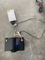
Back to the 120vac inverter at the start battery, extension cord to the rear, and a battery charger (power supply) plugged into the extension cord. That’s what you see in the pictures below. The 20’ white extension cord is another el cheapo #16.

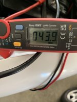
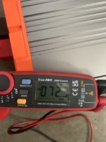
The pictures below also show that 40 amps of battery charging at the rear required 43.9 amps of charging current from the vehicle into the inverter up front. Not too shabby. Works for me with a 130 amp alternator at idle. Another picture shows 72.3 amps when I adjusted the charging amps to 70. A clamp-on DC ammeter is a valuable tool.

That means that however many 12v amps you need at the rear requires a few more from the front (alt). Using the about 10:1 rule of thumb for inverters, 120v, 15amps into your camper means about 150 amps from your vehicle/alternator. 15 amps X 10. That means about 150 alternator amps to produce 15 amps from an inverter to equal a 15 amp 120vac trailer hookup.

That same 10:1 means my 40 charging amps equals about 4 amps through the extension cord.

The 1000 watt inverter you mentioned could provide about 8 amps of 120v and require about 80 amps from the vehicle, and provide about 80 amps of battery charging at the camper.

My 10 year old camper trailer’s converter (inverter) outputs less than 14vdc except for short equalization periods that are higher than the lifepo4s supposed maximum. I need to investigate further.

I plan to use the power supply (charger) seen below instead of the trailer's converter when shorepower is available, or gggrrrr, when I HAVE to fire up that noisy-ass, supposedly quiet inverter generator.
 

Attachments

  • IMG_6686.jpeg
    IMG_6686.jpeg
    2.1 MB · Views: 4
  • IMG_6687.jpeg
    IMG_6687.jpeg
    1.2 MB · Views: 4
  • IMG_6676.jpeg
    IMG_6676.jpeg
    1.9 MB · Views: 4

Martinjmpr

Wiffleball Batter
To be honest the suggestion above to hard wire an inverter and use a 120V battery charger is pretty reasonable way to solve the long cable voltage drop issue.

Ideally you'd use more like a 40A to 50A charger for your house battery and that's going to take more like a 4AWG run to the back. If you put the inverter close to the engine then you only need a short 4AWG to it. There is some risk to running 120VAC through your truck but it's not insurmountable with good workmanship.

I like the idea of hard wiring an inverter but there simply is not enough space under the hood to put one and I don't want something that is connected all the time anyway, it's just not necessary.

Obviously there are multiple ways to skin this cat but I'm looking for one that requires the least amount of modification to my truck. As a plus, an off-vehicle solution has the advantage of being "portable" to another vehicle.

WRT the two times the batteries in the trailer ran down, both were somewhat unusual circumstances.

In the first one, in September, we were still using the 4+ year old FLA batteries that came with the trailer when we bought it. Making matters worse, we were camping in Oregon and while the weather was good - in fact, I'd say spectacular - we were under a 200' canopy of trees and even with a detached 100W solar panel augmenting the on-board 100W panel, I never had more than a few minutes of direct sunlight each day. The warm weather actually worked against us in terms of power consumption because it forced the 12v refrigerator to drain the batteries more quickly than if it had been chilly.

The second time, at Key West, my big mistake was in not bringing the detached 100W solar panel. Even though we had ample sunlight each day, the roof-mounted panel was on the "wrong" side of the trailer. The trailer has an arched roof and the front of the trailer was oriented to the West. The panel is on the right side of the trailer which means it was oriented to the North. Compounding this, we were there in late November when the sun is near it's lowest point on the horizon. Bottom line, we never got more than about 1.7A from the panel on the roof. If we had pointed the trailer to the East, which would have put the solar panel under more direct sunlight, or if I'd brought the portable 100W panel, it would likely have put in enough power to offset the draw from the fridge.

So, it seems likely that the ability to charge the batteries from the truck is not something I'm likely to need MOST of the time. Our upcoming trip to Texas this week will have us at sites with electric hookups every night so there's no issue there with power.

In any case, I'll continue to explore this and I appreciate all the suggestions and recommendations people make. This is why I like Ex Po, there are a lot of very knowledgeable people who are willing to think "outside the box" to get things done. :)
 

DaveInDenver

Middle Income Semi-Redneck
Indeed Martin, in your use case using a temporary inverter as a fail safe is a fine way to go. No question better than dragging a generator around for what-if.

I don't rely on the inverter solution but I do carry that AC/DC Powerwerx power supply sometimes for basically the same "just in case" reason.

I'm with you on interconnectivity and mix-and-match solutions. Kind of why I suggested having an Anderson SB120 (or bigger) on your battery.

I put SB175s on our cars and jumper cables but also inverters, spare batteries and everywhere. It's quick and safe, no worries of mismatched studs and terminal sizes, dropping a nut in the dirt, wrong polarity in the dark or a clamp shorting to the body. It's like garanimals for electrical.

IMG_4395_mid.pngIMG_4397_mid.pngIMG_4398_mid.png
 
Last edited:

Martinjmpr

Wiffleball Batter
Dave: That's pretty much what I'm looking to do. I assume I'd need those big two-handed crimpers you have for wires of that gauge?

Speaking of which, do you have a link to them? It seems that 8AWG is about the biggest wire I can crimp with my current crimper. I don't mind investing in a bigger crimper I'm just not sure where to look.
 

DaveInDenver

Middle Income Semi-Redneck
Dave: That's pretty much what I'm looking to do. I assume I'd need those big two-handed crimpers you have for wires of that gauge?

Speaking of which, do you have a link to them? It seems that 8AWG is about the biggest wire I can crimp with my current crimper. I don't mind investing in a bigger crimper I'm just not sure where to look.
You do need bigger crimpers for SB120 and larger, although they don't need to be particularly special. For the PP15/30/45 and SB50 using the Anderson specific crimpers is pretty important for them to be reliable but the SB120 and larger are just regular hex crimps.

To answer your question the heavy duty crimpers I have are FTZ model 94284 and my intermediate crimper is an Iwiss model HX-50B.

If you don't want to buy tools you can have a welding supply or battery shop crimp them on. For the most part SB175 terminals require a 50mm^2 hex crimper die. If crimpers are calibrated to wire gauge this will usually cross to the 1/0 AWG size hex. The smaller SB120 usually requires a 35mm^2 die, which may be marked as 2 AWG.

I would suggest buying at least one extra terminal if you can if you're using crimpers you're not familiar with since the marking and quality varies quite a bit (like those Iwiss, not top shelf tools). Sometimes a set of dies marked 50mm^2 are not quite that and you'll find the 35 or 70 works better. So having that one extra for a tester comes in handy...
 
Last edited:

burleyman

Active member
I thought of one other possible plus to the portable inverter system. If your charging system does not output a high enough voltage DC, the inverter becomes a constant 120vac voltage supply that draws a few extra amps from the battery when needed, somewhat like a DC-DC converter.

I connected one lifepo4 (13vdc) to an inverter, inverter 120vac to battery charger. Draws a few more amps than from my 14.4vdc vehicle's system.

Before infrared thermometer guns, for me it was guesswork with a finger test to gauge an overworked alternator. A painful fingertip resulted in later slobber-coated finger tests.
 

Martinjmpr

Wiffleball Batter
Just a quick follow up: I let the battery in the power pack run down to 85% on a recent camping trip just to test the 20' 8AWG cable to see if the voltage drop was causing the lower amperage on charging.

Here it is with the DC-DC charger connected directly to the LIFEPO battery with a short cable (about 24" total, 8AWG):

2025-01-28 12.16.26.png

Note that it is charging at 20.16A

Then I connected it through the 20' 8AWG cable and this was the result:


2025-01-28 12.15.33.png

I think I can safely say it is the voltage drop caused by the longer cable and small gauge that caused this.

However, rather than try to make a heavier gauge cable I think the smarter choice is going to be just getting a 1000W inverter and connecting the 30A 120v AC charger.
 

Martinjmpr

Wiffleball Batter
Also just adding that the DC-DC charger did a great job keeping the power pack battery charged on our recent 2 week trip to the Gulf Coast of Texas (Corpus Christi/Padre Island.)

Of course, it wasn't much of a test since we were experiencing record cold temperatures almost the entire time. Let's just say that the refrigerator sitting in my truck wasn't working very hard keeping the temps below 34 degrees overnight, seeing as how our overnight lows were frequently below 20!

It will get a better test on an upcoming trip to Washington DC in March.
 

Forum statistics

Threads
188,470
Messages
2,905,506
Members
230,428
Latest member
jacob_lashell
Top