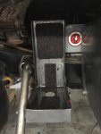
I have just done 45minutes of testing, easiest just to list all the tests and what the result was. I had an Auber temperature sensor on the OEM Bosch 90A alternator and used a IR heat gun on the 120A alternator measuring on the coil itself. (the brown/black bit on the picture)
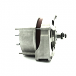
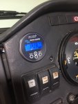
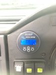
I also had a clamp on meter on the 120A alternator output. The battery monitor measures the the combined input into both sets of batteries, so the output of the 90A alternator would be the difference between the total measured on the BMV712 and the clamp on meter less the normal current ( 10A) to run the truck. Inside the shed, the ambient temperature was 23C and got up to 25C after running the truck. I have been discharging the batteries for the past week, guessing they would be down to about 60-70%. They were were all down to 13.2V
1. Idle test - I started the truck and just let it idle - about 700rpm. alternators charging batteries independently
2. Truck at 1200rpm - charging batteries independently - minimal extra load
3. Truck at 1200rpm - charging both batteries in parallel - minimal extra load
4. Truck at 1800rpm - charging both batteries in parallel
5. Truck at 1800rpm - charging batteries independently - maximum load ( all spot/headlights, ,main engine fan, ac etc.)
6. Truck at 1800rpm - charging both batteries in parallel - maximum load ( all spot/headlights, ,main engine fan, ac etc.)
7. Truck at 2000rpm - charging both batteries in parallel - maximum load ( all spot/headlights, ,main engine fan, ac etc.}
On the first test, at idle the voltage jumped to 13.7V and current up to 20A. The 90A rose from 20C and stabilised at 40C after about five minutes. The 120A alternator got to a stable temp of 65C. The 120A alternator was putting out 20A, so that means only 10A was going into the main batteries, so the 90A was only putting 10A into the starter battery. This was the test the the video showed would blow up the alternator, and nothing of the sort happened. Temperatures on the alternator did not rise at all. If I lowered the idle down to less than 700rpm, the current going into both batteries dropped down to zero.
Second and third tests, the total input into the batteries was 90A and it did not make any difference being in parallel or independent. The real change was was in the output of the 120A alternator. When run in parallel with the 90A, it was putting out 60A, so that means the 90A alternator was putting out 40A. The temperatures on the 120A alternator stayed at 65C. When run independently, the 120 alternator output rose to 85A, so than means the 90A was only putting out 15A into the starting battery, which has rose to 13.85V whilst the main batteries remained at 13.7V. The temperature on the 120A alternator rose over about a minute to 95C and stabilised.
Test 4 showed no real change other than the total output going to 120A, and in parallel mode, the 120A alternator temperature dropped down to 85C and stabilsed.
Turning on all the electrical load - this is about 120A in total, and with both alternators in parallel, the current going into the batteries dropped down to 50A. The output on the 120A alternator rose to 100A, and the temperature rose up to 110C and stabilised. The battery voltage dropped down to 13.6V. The 90A alternator went up to 55C. This temp measurement was on the casing, so I checked the difference between the casing and the coil on the 120A alternator, than the casing was at 75C. So I am guessing this meant the coils on the the 90A would be around 100C. So that means the total output of both alternators was 170A, of which the 90A alternator started to take up the load of charging the batteries. I kept this test running for ten minutes, and it stayed constant.
Running the two alternators independently with maximum load, saw the output of 120A alternator go up to 110A, the temperature on the coil increased to 115C quickly then stabilise. The total input into the batteries dropped down to 20A. Voltage on the main battery was 13.6V, and increased to 13.8V on the starter battery. So, I think that means the main batteries were discharging by 10A, and the starter battery was getting charge of around 30A. I carried on this test for 10 minutes as well. Switching off the main engine fan (25A) load saw the BMV current change by the same amount.
I increased the revs to 2000rpm, and it made no difference to anything to any of the above, so I think that the alternators are running at their maximum capacity.
So, my conclusions are the if I run both alternator in parallel, then I will have no problems at all, and during the day, I will be charging the main batteries and starter at a rate of around 120A ( about 30A each) and around 13.8V. I will need to do a long run to see what will happen when the batteries get full, but I am thinking that since the alternators only put out 14.2V, I doubt that will happen. The solar system is set to no more than 14.5V, so even with that, I will never trigger the built in BMS shutdown of 15V on any of the batteries, but it also mean that I will not be charging the batteries to this full capacity, which might not be a bad thing.
So now I have to decide whether I really need to get a bigger alternator, of just used the built in feature of the Blue Sea Systems ML-ACR so that it will automatically run the two systems in parallel after about 3-5 minutes after starting and always run both alternators in parallel. I can get a 270A alternator from Mechman for around $800, so will probably get it.
https://www.bluesea.com/products/76...rging_Relay_with_Manual_Control_-_12V_DC_500A
One thing I might invest in is something like this to protect the alternators.
https://sterling-power.com/products/alternator-open-circuit-protection-device and maybe I should look at getting a smaller pulley for the 120A to increase it efficiency at lower rpm, but to be honest, I hardly ever leave the truck idling, and even in off road conditions, we seldom trundle along at less then 1500rpm. The big LED spotlights on the roof draw 10A each, but we only used all of them when on dark dirt roads, I normally just have one pair on as that is more than adequate. The inner pair of spotlights are set to light up the sides of the road more than in front anyway,
The next test will need to be done on the road, and when there is a high ambient temperature over 40C to see if everything does work reliably. I think I will move the temperature sensor to the 120A alternator and epoxy it directly to the brown bit on the 120A alternator coil, as that is what seems to get the hottest. I could wire in the Auber gauge on the dash so that it would automatically make run both alternators in parallel if it got hot.
All in all, I don't seem to be having any problems at all with this new setup, time will tell I guess.

