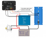
Victron Energy: Alternator/Solar Charging - LFP Battery System

dreadlocks

Well-known member
I'm not charging at all via alternator, I put a diode on my feed line from the truck so the LFP can power the brakes and so does the tow vehicle.. but it dont provide a charge current.

I'm relying entirely on solar or ac charger.. my fixed solar usually does just dandy charging while driving, better than the stock wiring would.
 

shade

Well-known member
Ah, ok. I was looking at one of your diagrams and wondered why I wasn't seeing an alternator connection. :)
With a trailer, it makes sense to keep it tidy like that, since leaving the trailer behind has no impact on charging.

I'm trying to keep weight down and starting with a single panel for now, so alternator charging is necessary.
 

luthj

Engineer In Residence
That relay would work. A battery is a battery, LFP has a lower internal resitance, so it can accept higher charge rates at the same voltage. Nothing magical about doing some quick math with resistance and voltage drop to find the desired max charge rate. That is what you are doing, is setting the max charge rate. That is determined by testing at idle. The system is self balancing, as alternator temperature, and the batteries acceptance rate provide feedback. Since you wouldn't be using a DC-DC you are limited in how much tuning you can do anyways.

Here is how I would approach the alternator charge design. I would contact victron and ask for charge rate vs charge voltage plots. Say for 13.5 to 14.4V, you are looking for the plot that has the sustained current (5 minutes or more) which is under the anticipated alternator max output at idle. Most alternators can make 80% of their rated current at idle. Subtract 40-60A for engine/lights/fans. The remainder is you estimated max current. Lets say 100A.

Look at victrons plots, lets say that 13.5V results in a max sustained current of 90A. Now we have the V and I, so we can calculate the R. V=I*R. V= Alternator voltage minus 13.4V. Assuming an alternator voltage of 13.9V 0.5=90*R so R= 5.5 milliohms.

Assuming a wire run of 20ft round trip you would want to use 1AWG which yields 2.5 millohm. Assuming 1 milliohm from connections, and another 2 from the fuses, you will effectively limit the current. You can fairly easily swap in a smaller fuse (say 100A instead of 150A) to fine tune the max current.

Most folks don't mention this, but automotive alternators are self limiting. When the field current hits its max (usually around 10A), the alternator will not produce any more output current. Increasing the load simply drops the alternators output voltage until equilibrium is met.
 

dreadlocks

Well-known member
its the "trailer brakes" line..

in a truck I think I'd be looking hard at a Sterling DC Charger, probably the 60A for that big LFP.
 

shade

Well-known member
That relay would work. A battery is a battery, LFP has a lower internal resitance, so it can accept higher charge rates at the same voltage. Nothing magical about doing some quick math with resistance and voltage drop to find the desired max charge rate. That is what you are doing, is setting the max charge rate. That is determined by testing at idle. The system is self balancing, as alternator temperature, and the batteries acceptance rate provide feedback. Since you wouldn't be using a DC-DC you are limited in how much tuning you can do anyways.

Here is how I would approach the alternator charge design. I would contact victron and ask for charge rate vs charge voltage plots. Say for 13.5 to 14.4V, you are looking for the plot that has the sustained current (5 minutes or more) which is under the anticipated alternator max output at idle. Most alternators can make 80% of their rated current at idle. Subtract 40-60A for engine/lights/fans. The remainder is you estimated max current. Lets say 100A.

Look at victrons plots, lets say that 13.5V results in a max sustained current of 90A. Now we have the V and I, so we can calculate the R. V=I*R. V= Alternator voltage minus 13.4V. Assuming an alternator voltage of 13.9V 0.5=90*R so R= 5.5 milliohms.

Assuming a wire run of 20ft round trip you would want to use 1AWG which yields 2.5 millohm. Assuming 1 milliohm from connections, and another 2 from the fuses, you will effectively limit the current. You can fairly easily swap in a smaller fuse (say 100A instead of 150A) to fine tune the max current.

Most folks don't mention this, but automotive alternators are self limiting. When the field current hits its max (usually around 10A), the alternator will not produce any more output current. Increasing the load simply drops the alternators output voltage until equilibrium is met.
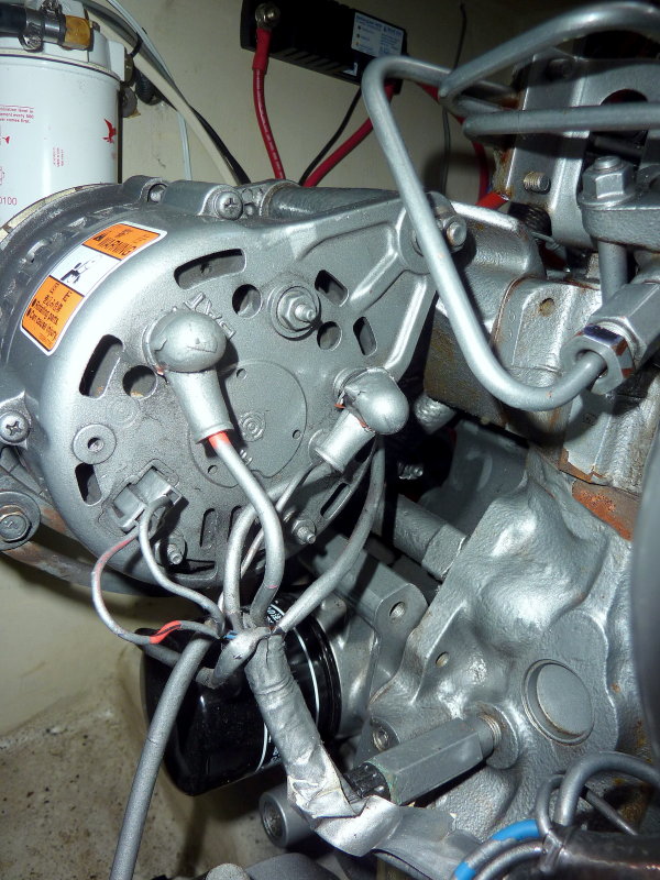
I see that I failed to mention my truck has a 130A alternator; fixed in the OP.

I'll contact VE if I don't find the information first.
 

luthj

Engineer In Residence
I will locate the thread if I can, but some testing on the Sterling B-B chargers has shown issues. They have poor cooling and high waste heat generation. In warm or hot weather they will rapidly heat up, and self limit. In 95F+ weather one user documented the unit dropping to 20A within 15 minutes. From those experiences I would hold off on buying their higher output units.

For reference, my bosch 200A alternator will make 130-150A at idle. My engine needs about 20A to run, add another 7A for the AC and 5-8A for lights if driving at night. so I have about 90-100A available at idle.

Again, folks are really concerned about blowing alternators, but it just doesn't happen often. How many 200A+ winches are running around attached to factory alternator systems? You want to avoid running for hours at a time at 100%, but with a 160A battery, it will be almost full in 1 hour, and tapering after 1.5 hours!
 

shade

Well-known member
I want to stick with Victron anyway, so adding a Sterling charger isn't ideal.

Looking more at the BMS 12/200, I think it basically performs a similar function as a Cyrix relay with regard to isolating the starting & house batteries.

"The first function of Power Port AB is to prevent the load connected to the LFP battery from discharging the starter battery. This function is similar to that of a Cyrix Battery Combiner or Argo FET Battery Isolator. Current can flow to the LFP battery only if the input voltage (= voltage on the starter battery) exceeds 13V. Current cannot flow back from the LFP battery to the starter battery, thus preventing eventual damage to the LFP battery due to excessive discharge."
 

Alloy

Well-known member
I want to stick with Victron anyway, so adding a Sterling charger isn't ideal.

Looking more at the BMS 12/200, I think it basically performs a similar function as a Cyrix relay with regard to isolating the starting & house batteries.

"The first function of Power Port AB is to prevent the load connected to the LFP battery from discharging the starter battery. This function is similar to that of a Cyrix Battery Combiner or Argo FET Battery Isolator. Current can flow to the LFP battery only if the input voltage (= voltage on the starter battery) exceeds 13V. Current cannot flow back from the LFP battery to the starter battery, thus preventing eventual damage to the LFP battery due to excessive discharge."


It won't suit your 130A alternator.......The maximum fuse rating is 100A (limiting charge current to approximately 80A).
 

shade

Well-known member
It won't suit your 130A alternator.......The maximum fuse rating is 100A (limiting charge current to approximately 80A).
True, but I doubt the alternator would be able to push 80A to the LFP battery for long, though. From what I've seen, that's expecting a lot from a light duty, small frame alternator with internal regulation.


shade

Well-known member
Again, folks are really concerned about blowing alternators, but it just doesn't happen often. How many 200A+ winches are running around attached to factory alternator systems? You want to avoid running for hours at a time at 100%, but with a 160A battery, it will be almost full in 1 hour, and tapering after 1.5 hours!
That's a very good point, especially since I doubt I'll be taking the battery down anywhere close to even 10% SoC. I also like the simplicity of passive regulation. I could always add some hardware to the equation later if the alternator was being abused. A Cyrix-Li-ct 12/24V-230A will do the trick, and I think this diagram will be the way to go for alternator charging.

1568626453582.png


"In the layout above the alternator is charging a conventional start battery at all times. The start battery is connected to the Lithium Ion battery via the Cyrix-Li-Ct which is a battery combiner controlled by the BMS. When the Lithium Battery is full the combiner gets shut off but the alternator continues to charge the start battery. There is no current limiting shown, the alternator had better be up to the job or have active temperature control."

"I did have a question about all these systems, what happens when the engine is stopped? Does the lithium battery drain into the conventional battery? Here is the official answer: 'The Cyrix-Li-ct will disconnect when the engine isn’t running and the starter voltage starts to drop much like the regular Cyrix.'"

I considered using a Smart BatteryProtect instead of the Cyrix, but it would allow current to pass from the LFP to the start battery.

"Caution: uncontrolled reverse current will flow through a Smart BatteryProtect if Vout > Vin. Therefore, never use a Smart BatteryProtect for battery to battery charging."
 
Last edited:

Alloy

Well-known member
That how I would do it but I'm wondering what happens when solar is added? The Cyrix may need on/off from the ignition.
 

shade

Well-known member
That how I would do it but I'm wondering what happens when solar is added? The Cyrix may need on/off from the ignition.
Good question. When checking the Cyrix manual, it states that the relay closes in response to a voltage increase on either post, so solar charging would seem to mean a closed relay, which would connect the start & house batteries. Not what I want, since my goal is to leave the start battery out of the house loads altogether.

Maybe an ArgoFET battery isolator would be a better choice:

"Similarly to diode battery isolators, FET isolators allow simultaneous charging of two or more batteries from one alternator (or a single output battery charger), without connecting the batteries together. Discharging the accessory battery for example will not result in also discharging the starter battery."

Then I'd have to add a Smart BatteryProtect between the ArgoFET and house battery for disconnecting alternator charging.
 
Last edited:

Alloy

Well-known member
I like Plan A (easy to trouble shoot) but I'd inquire with Victron as to adding a switch or relay to control a Cyrix
 

shade

Well-known member
I found this on the Victron forum, and it's very similar to what I want to do. Maybe a BMS 12/200 with a separate BatteryProtect for each charge source is the way to go after all. The BMS 12/200 regulates alternator current, isolates the batteries when the engine is off, and it allows solar charging without potentially closing a Cyrix relay, as @Alloy mentioned.
_________________________________________________
"I'm considering a lithium system in a Sprinter Van using the BMS 12/200, with the batteries being charged by both the alternator (when the vehicle is running), and solar (when the sun is available). Obviously the alternator would be connected to the AB port and will shut off in overvoltage, etc scenarios. Should the solar charge controller then be connected to the LB port? Will the charging shut off on the LB port in an overvoltage scenario, but maintain discharging / power to DC loads? The solar charge controller in use would be the SmartSolar MPPT 100/30."

Victron Staff: "Yes, that exactly how it works."
__________________________________________________

Basically this diagram, with solar input on the top post of the 12/200, and BatteryProtects just before the 12/200 to prevent overcharging from either source.

1568641733880.png
 
Last edited:

Forum statistics

Threads
188,251
Messages
2,904,518
Members
229,805
Latest member
Chonker LMTV
Top