You are using an out of date browser. It may not display this or other websites correctly.
You should upgrade or use an alternative browser.
You should upgrade or use an alternative browser.
Victron Energy: Alternator/Solar Charging - LFP Battery System
- Thread starter shade
- Start date
shade
Well-known member
I found another article that touches on this problem:
How do I charge two battery banks on my boat and still keep them separate?
Basically, he lists five ways:
Manual switch - no thanks
Two alternators - not going to happen
Blue Sea ACR - not LFP battery friendly
Balmar Digital Duo Charge - interesting option, but it tops out at 30A
Victron ArgoFET battery isolator - simple, effective, and another VE product
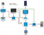
I've been reading more about the ArgoFET isolator, and I think it may be the way to go. Time to whip up a diagram and upload it here and the VE board to see if it makes sense.
shade
Well-known member
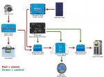
Ok, here's the beginning of something. This is the first time I've used draw.io, and it's pretty cool (thanks @dreadlocks). I'll refine it more as time goes on, but please take a look at the general layout and let me know what you think. I'll post it to the Victron board and see what they say, too.
The ArgoFET 200-2 is a 200A x 2 isolator. I don't really need 200A capacity, but the lower model tops out at 100A, and it's possible the alternator could exceed that briefly.

The ArgoFET 200-2 is a 200A x 2 isolator. I don't really need 200A capacity, but the lower model tops out at 100A, and it's possible the alternator could exceed that briefly.

dreadlocks
Well-known member
hrmm.. you dont need 3 disconnects.. your alternator feed is your charge circuit, put your solar/ac charger on that leg.. also if your letting the BMS control them just get the Dumb Battery Protects, put them in LFP mode and they are just dumb solid state relays and it disables its internal smarts.. having bluetooth just cost more and wont let you do anything.
shade
Well-known member
hrmm.. you dont need 3 disconnects.. your alternator feed is your charge circuit, put your solar/ac charger on that leg.. also if your letting the BMS control them just get the Dumb Battery Protects, put them in LFP mode and they are just dumb solid state relays and it disables its internal smarts.. having bluetooth just cost more and wont let you do anything.
So I'd run the output of the solar charge controller into the 220A BatteryProtect that sets between the ArgoFET and the battery?
Using the dumb BPs would save a few dollars. Makes sense.
Last edited:
dreadlocks
Well-known member
Yeah route all Charge Supplies to the same side of that solid state relay, then you wire that up to the BMS as the Charge/Input Circuit.. all your loads up to another solid state relay wired to BMS discharge output.. If you want a manual master disconnect (suggested) put it right at the LFP.
Looks like Victron released an update that has a fixed absorb time for LFPs now, yay.. https://www.victronenergy.com/blog/...5-9-solar-charger-improvements-and-much-more/
Looks like Victron released an update that has a fixed absorb time for LFPs now, yay.. https://www.victronenergy.com/blog/...5-9-solar-charger-improvements-and-much-more/
shade
Well-known member
Ah, ok. I thought I needed to keep the charge inputs discrete. I'll be putting in a master disconnect, fuses, etc. later.Yeah route all Charge Supplies to the same side of that solid state relay, then you wire that up to the BMS as the Charge/Input Circuit.. all your loads up to another solid state relay wired to BMS discharge output.. If you want a manual master disconnect (suggested) put it right at the LFP.
Looks like Victron released an update that has a fixed absorb time for LFPs now, yay.. https://www.victronenergy.com/blog/...5-9-solar-charger-improvements-and-much-more/
Time to do some more drawrings.
dreadlocks
Well-known member
If your happy with the Victron BT app direct in the battery and dont wanna buy/build a Venus interface then also consider the minibms.. if you have aspirations for connecting all the victron gear together with a central controller/display then stick w/the VE.Bus option.. and in that case you might not need the BMV really unless you want a nice simple (expensive) display.. but there's better/fancier display options going down that path.
dreadlocks
Well-known member
looks good, if it were me I'd add in some manual 3 way switches between the BMS and the Charge/Load relays.. that way in the field you can make an "executive" decision and over-ride the BMS.. have on/off/auto and leave it on auto mostly and hide the switches somewhere curious fingers wont find em.
shade
Well-known member
I don't plan on having one of the fancy VE displays. I'd rather have more Amp hours than animations. I may want a Phoenix inverter that could make use of the VE.Bus BMS, so I'll keep it.If your happy with the Victron BT app direct in the battery and dont wanna buy/build a Venus interface then also consider the minibms.. if you have aspirations for connecting all the victron gear together with a central controller/display then stick w/the VE.Bus option.. and in that case you might not need the BMV really unless you want a nice simple (expensive) display.. but there's better/fancier display options going down that path.
Can I can get all of the functionality of the BMV-712 via the Bluetooth app? If so, I'll dump it.
Cleaned up the disconnects above.You only need a single charge disconnect as mentioned. You will want a method to disconnect the alternator regardless (you have several options as discussed).
I thought that the BatteryProtect charge disconnect took care of disconnecting the alternator, no?
dreadlocks
Well-known member
I'd have to see more than the demo app, the demo kinda implies you can see SOC but I'm not sure.. mebe not? You'd think the BT app would be able to show load/charge rates, calculated SOC and everything the BMV could but better.. but perhaps not without an external interface, the onboard processing might be too limited.. would be a good question for their support.
shade
Well-known member
Now that I think about it, there has to be a shunt to read from, right? Without a BMV attached to a shunt, I doubt that information is available.I'd have to see more than the demo app, the demo kinda implies you can see SOC but I'm not sure.. mebe not? You'd think the BT app would be able to show load/charge rates, calculated SOC and everything the BMV could but better.. but perhaps not without an external interface, the onboard processing might be too limited.. would be a good question for their support.
dreadlocks
Well-known member
one would hope it had a shunt internally so BMS would be capable of disconnecting on overload situations.. but perhaps they just use thermal monitoring for that? shrug.
This is where I'd like to tie everything together into a lil RPI and add in my own layers of monitoring and alarming, could set all my own limits that are conservative enough to ensure decades of longevity from the cells.. I know what normal looks like for my situation, and can tighten up alerts so the moment something is not behaving correctly I'm aware of it without having to be a paranoid helicopter parent.
This is where I'd like to tie everything together into a lil RPI and add in my own layers of monitoring and alarming, could set all my own limits that are conservative enough to ensure decades of longevity from the cells.. I know what normal looks like for my situation, and can tighten up alerts so the moment something is not behaving correctly I'm aware of it without having to be a paranoid helicopter parent.
Last edited:
Similar threads
- Replies
- 6
- Views
- 2K
- Replies
- 30
- Views
- 8K
- Replies
- 3
- Views
- 2K
- Replies
- 0
- Views
- 854


