Blender, My LX450/FZJ80 + FJ45esk + GM + Land Rover crazy concoction

Metcalf

Expedition Leader
I got a few interesting packages in the mail today....


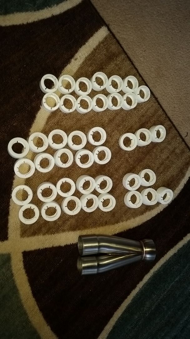
I have been playing around with having some parts 3D printed. I also purchased a 2.25 to 3" merge pipe in purge TIG welded stainless.

This is how the 3D printed parts work in combination with a little cheap/free 2" heavy wall packing tubes.....


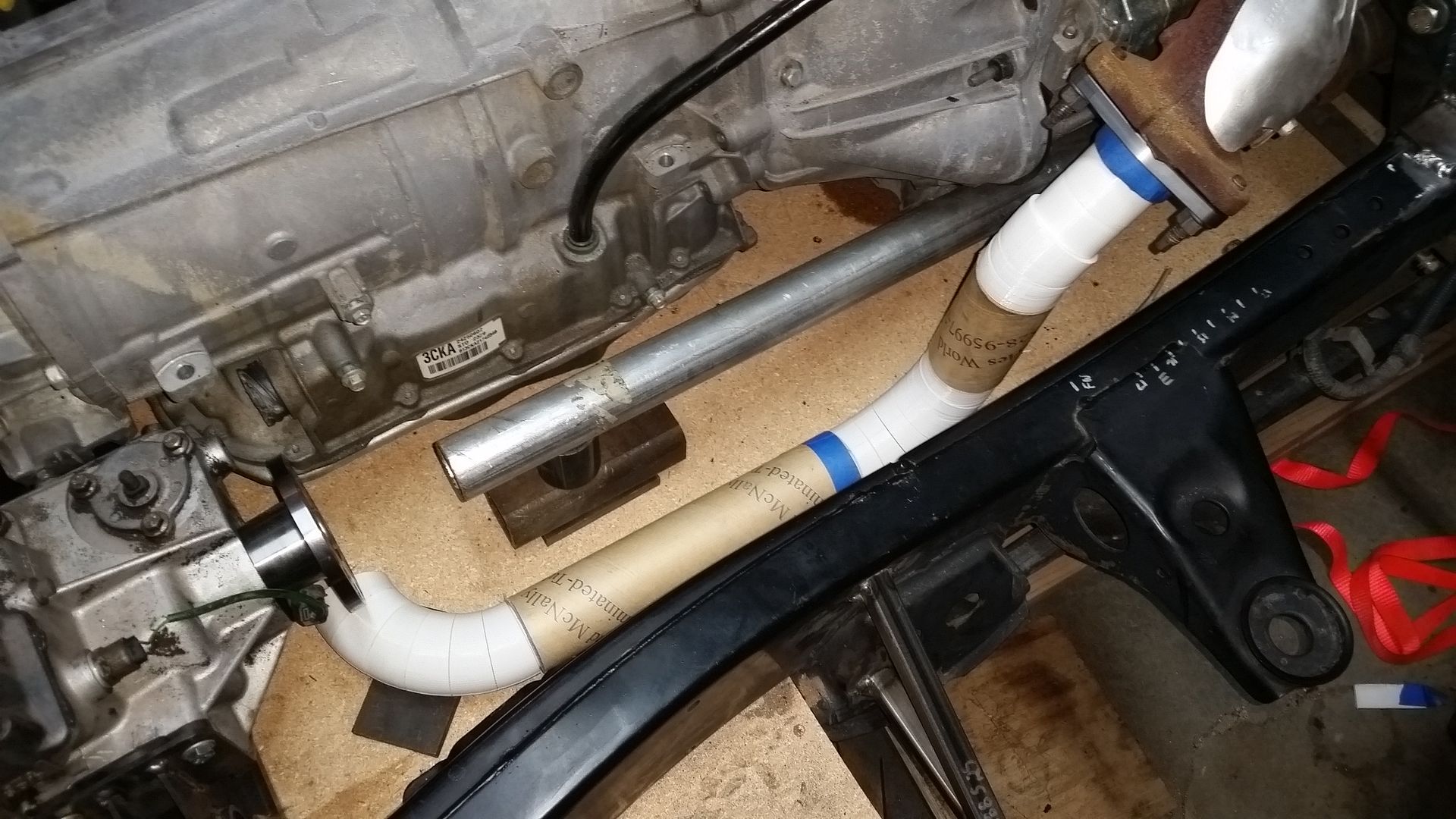
This took me all of about 15 minutes to mock up....

This is NOT my idea. I just reversed engineered it for my use. The original idea came from ICE engine works.

http://www.icengineworks.com/

They pioneered this type of system for the construction of custom headers.

I twisted the idea around a little bit for my use. I wanted to use the same technology to plan out the forward Y-pipe part of my exhaust. They do not offer a 'block' in 2.25" diameter with a 3.5" CLR bend. I was able to reverse engineer the idea for my uses and have then 3D printed for me.

My improvement for my use of the idea, in exhaust work, was to be able to use some cardboard shipping tube for the longer straight sections. I designed a 1" long block that can either be used to fit between bends or can either be inserted into cardboard packing tubes with a 2" diameter. The heavy wall 2" ID shipping tubes just happen to be 2.3" OD which is close enough to simulate the 2.25" OD tubing I am using. The thicker tubes are easy enough to cut with a fine tooth wood saw.
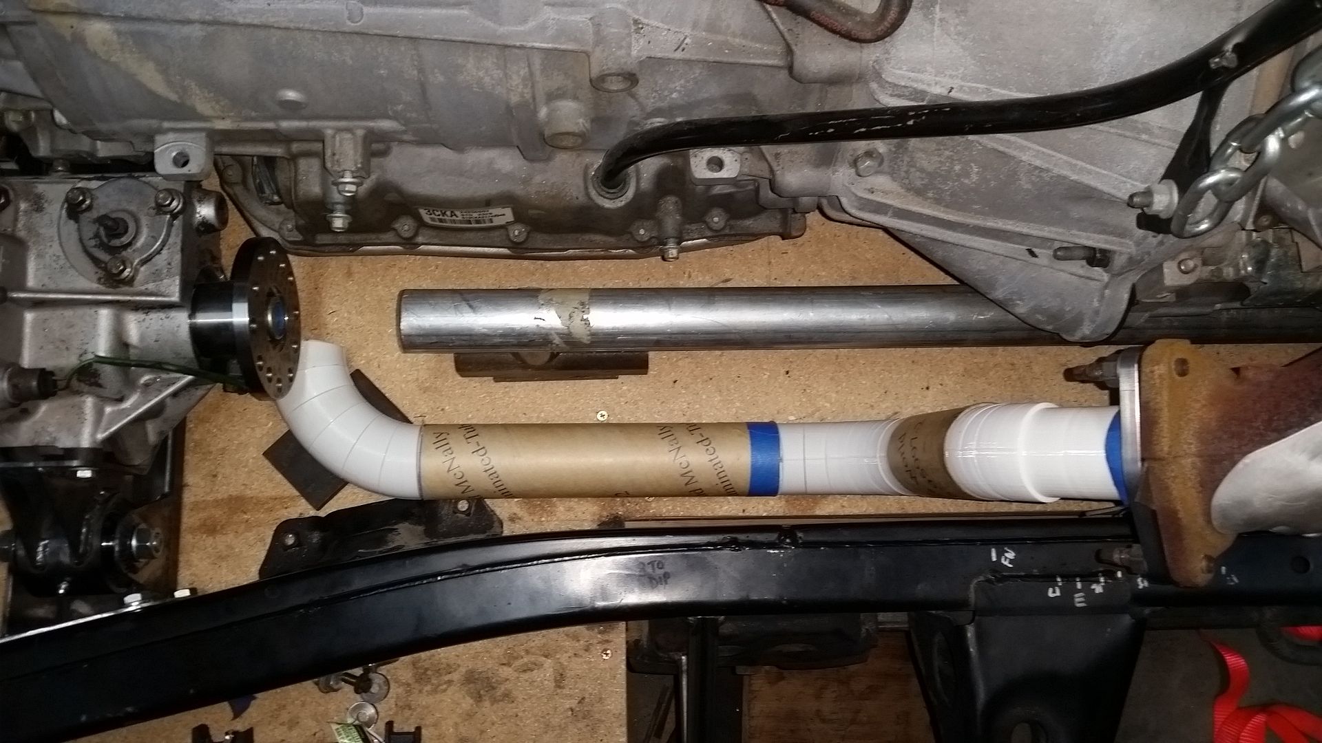
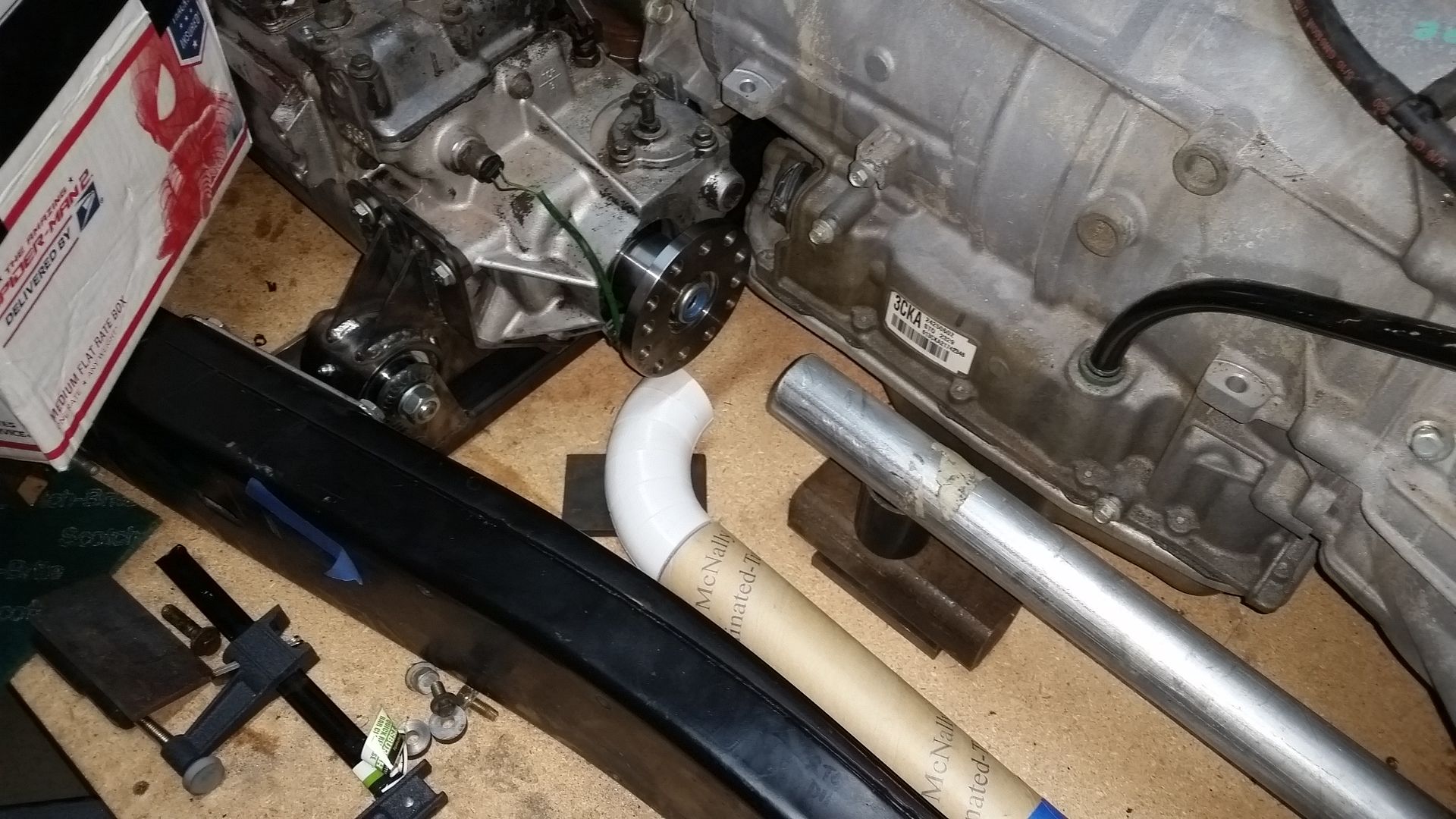


A few more views.

I can't wait to use the 'data' provided by the mockup to order the amount of 'bend' I need. I will be able to map out each side easy enough. I will not have to waste expensive stainless steel tubing doing a trial and error fitment. Once you have a complete model of one side, you can look at how you might be able to eliminate weld joints by using the tangent 'legs' on common bend angles. Very neat technology....
 

locrwln

Expedition Leader
That is awesome. When I saw the original pictures showing your "exhaust" parts, I thought you had bought their kit. I looked at it, but it was too much for a one off project, so I chose to just buy some headers and go from there. I was going to ask if you had ponied up for the kit, but seeing that you printed your own is very cool.
Jack
 

Metcalf

Expedition Leader
That is awesome. When I saw the original pictures showing your "exhaust" parts, I thought you had bought their kit. I looked at it, but it was too much for a one off project, so I chose to just buy some headers and go from there. I was going to ask if you had ponied up for the kit, but seeing that you printed your own is very cool.
Jack

Thank you, the idea worked really neat so far. I could have muddled my way through it the old fashion way, but I thought I would try and learn a new trick.
 

herm

Adventurer
i have the same engine setup for a 72 wagoneer out of a 2011 truck, though i plan on using the GM manual shift transfer case out of a w/t 2500 that bolts up to the 6l90e and the 5.3 L. I am interested in what who is doing it / helping with your wire harness and computer programming.

i love watching the fab work progress.
 

Metcalf

Expedition Leader
Trying to get back in the groove....


I purchased a pre-made merge pipe. Looking back, I should have probably just built my own again. It is an ok part, but for the money, meh.

I added a stainless mounting tab to the merge pipe. I suck at doing a thick to thin fillet weld in stainless. The merge is hard mounted to a bracket that sandwiches onto the the drivers side mount pad on the adapter. I elected to hard mount the merge to the adapter similar to how I did the exhaust on my flat fender. That seemed to work really well for me on that car. It seems to keep the exhaust more stable with tight clearances.

Once I had the merge mounted, I was about to dial in the proposed path of the exhaust on the passenger side. Once that was done, I was able to record all the information from the 'exhaust legos' I had printed. Once that information was recorded....along with a few more pictures of everything for a good visual record...I then broke down that side. The drivers side went a lot quicker for the most part. With the mock up system, I was able to design the drivers side in about 15 minutes. I also recorded all that information.

Now I can break down how many bends and how much straight I need to purchase to build each side of the Y-pipe.

While I wait for the exhaust parts to get here, I am going to stick the body back on and start roughing out the body mount system. Hopefully I can make it start to look like something again!
 

Metcalf

Expedition Leader
Bye Bye body mounts....


I figured it was time to prep the frame for the new body mounts by removing the old ones. My hope is that I will be able to combine the body mounts, rocker tube supports, and cage tie-in points all into one clean unit.

I needed something to do while I wait for the exhaust tubing to show up.

That monster long blade on the saws-all was the way to go. Unfortunately, I didn't think of that till the 2nd side. Amazingly the blade holds up really well to sawing while it has some bend in it.

Now I need to set the body back on the frame again...on...off...on...off...on.

I am going to be trimming about 3" of material off the rocker panels in order to make room for the rocker protection tubes. That should be easier with the body of the frame instead of the table. The rocker tubes are going to be frame mounted, but I want the most clearance possible. The FJ40 body has a pretty tall rocker panel with a lot of wasted space. I think I can trim off enough to allow me to use a 2" tall rocker tube (plus body clearance) and still have more clearance than 'stock'. Removing that vertical height off the rocker panel should also make the body look less tall. To make things a little more interesting. I want to retain a 90 degree flange on the bottom of the sheetmetal rocker panel. I think I can reform that flange pretty easy with a little bendy stick tool ( ala Project Binky ). I will also need to move the front corner near where the fender attaches...that might require some sectioning of the panel to weld that formed part back into the main panel.

I think it is also just about time to pull the engine table out and let the tires support the weight of the chassis! I wonder how that is going to change the look of things. I think the body will be dropping almost 1-2" perhaps.
 

locrwln

Expedition Leader
I know the feeling of on again, off again. Mine has been motor in and out, in and out; transfer cases in and out...

I think I am done with that part though.

I ran out of my long sawsall blades and had to use a short one I had lying around. It sucked.

Jack
 

Metcalf

Expedition Leader
I know the feeling of on again, off again. Mine has been motor in and out, in and out; transfer cases in and out...

I think I am done with that part though.

I ran out of my long sawsall blades and had to use a short one I had lying around. It sucked.

Yeah, Easter Jeep Safari made me slow down for a little bit. Now I am getting back into the groove. I really want to take this thing over to EJS next year along with my flat fender.

I just picked up my steel order this afternoon, now I have everything I need to finish most of the fab work....bumpers, rockers, the framework for the tub, etc.
Hopefully things move along at a decent pace now.
 

RMP&O

Expedition Leader
I personally hate the sawzall!! So many busted blades and I really dislike when it gets stuck or busts a blade and jumps at you. Plus I have busted a sawzall or two before in addition to many many blades. Blades are expensive where I live too. I use a 4" grinder with cut off wheel or die grinder with cut off wheel or plasma torch. I have an 80 frame I cut all the body mounts off of and also the front suspension brackets, short work of it with the plasma cutter and not to much time on the grinder cleaning up after.

Dig your cross member, I need to build one like that for a TD engine and 5spd swap I am working on in an old Nissan Patrol pickup.

Cheers
 

Metcalf

Expedition Leader
I personally hate the sawzall!! So many busted blades and I really dislike when it gets stuck or busts a blade and jumps at you. Plus I have busted a sawzall or two before in addition to many many blades. Blades are expensive where I live too. I use a 4" grinder with cut off wheel or die grinder with cut off wheel or plasma torch. I have an 80 frame I cut all the body mounts off of and also the front suspension brackets, short work of it with the plasma cutter and not to much time on the grinder cleaning up after.

Dig your cross member, I need to build one like that for a TD engine and 5spd swap I am working on in an old Nissan Patrol pickup.

Cheers

Thank you. The crossemember worked out pretty well. I may loosen up the mounting holes another size. Getting everything into position can be a little odd, but I am working from the top on the table instead of the bottom like it will be normally. I am going to try and built a bolt in temporary crossmember that bolts to the factory frame side mounts that will support the transmission and let me drop the entire adapter and transfer case as one unit with the crossmember still attached. I think that will be handy down the road. I am very interested to see how it holds up to some abuse. One of the design goals was to be able to turtle out the car on the belly without damage.

I used a grinder on the 1st side, it took forever. On the 2nd side I tried the saw. It worked WAY better overall. I did use the grinder to start a groove for the saw blade in the corner where I wanted to start. That helped. The saw let me get into the area I needed to with much less work. With the grinder I had to cut the bracket of in pieces because I couldn't fit the grinder into the space there I needed to make a cut.

It is always interesting what you learn as you go. The 2nd side probably took me 1/4 time.
 

Metcalf

Expedition Leader
Just keep trucking.....


I stopped by my dealer....supplier....errr....steel supplier. It is so nice to have a decent place to deal with local to me again. I can order through my work, but they only deliver once a week. Sometimes I need a fix more often than that.

Ignore the 3x3x3/16 on the left, that is going to be a tube bender stand/frame.

The rest is going to go in the new truck project. I am going to use the 2x3x3/16 to fabricate the bumpers and rocker protection. It is a little heavier than I would have liked, but I have some longer spans on this chassis. The rear of the frame is VERY wide and I want some kind of tow/haul attachment point in the middle. The rockers are also going to be fairly long. The support should be fairly evenly spread out, but this material should hold up well over time at the total vehicle weight. I plan on pushing this vehicle a little harder than my flat fender so a little extra protection is probably a good thing.

The 2x2 and 1.5x1.5 square tube, both 1/8" wall, are going to be used to form the 'framework' for the top and rear section of the body. This is basically going to be the 'cage' also. The 2x2 will be used for the B-pillar along with a spreader bar at the floor that will run side to side. The rest of the framework is going to be made from the 1.5 square tube along with some mandrel bends in the same material for the rear corners at the waistline of the body. I will use a little 1.5" DOM round tube for the A-pillar uprights.

This framework is going to be what all the body panels attach onto. Most of the panels below the waistline will be steel sheetmetal and welded in place. All the 'top' panels will be aluminum and will bolt onto this framework. My hope is that I can construct a 'modular' hard top system that will allow me to have a convertible of sorts. The roof will stay in place, but yet be replaceable if damaged. The rear window panels will be removable/replaceable. My hope is that I can make those panels store in the bottom part of the body when I want that open air feeling. The doors are most likely going to be a metal 2pc unit where the upper part of the door will be removable also. Anyhow...stay tuned for all the stuff. That is still a few months away, but if I can pull it off should be very unique.

In other news....


I removed another pair of body mounts toward the rear of the frame.


These mounts on the front of the frame are my next target. That front crossmember will also need to be removed to make room for the winch. I will be adding a crossmember under the grill to replace it along with a welded bumper assembly. I also want to change the profile of the front of the frame. The bumper is basically going to sit on top of the existing frame rail I think. I will probably taper cut the ends of the factory frame rails and box everything back in.

Oh....and I also stuck the tub back on the frame again in preparation for the construction of the body mounts, rockers, and 'cage' tie-ins. It will be SO nice to have the body mounted to the frame finally!
 

Metcalf

Expedition Leader
Last night I didn't get anything done on the project really. I did FINALLY get some dang light in the shop!


Now that I can see what I am doing and stop fabricating by feel thing might start to get interesting! The lights are so bright that I think I need sun glasses or a hat. If a man cave has light....is it still a cave?
 

Metcalf

Expedition Leader
Time to tackle the rocker protection / body mounts / cage mounts....but first lets make a tool....


I made this little 'bendy stick', ala Project Binky, to allow me to form flanges on the rocker panels after I trim them. It is just a block of scrap steel with a slit cut in it with the band saw...and then widened with a 1/16" cut off wheel in the grinder. That seems to match 16 gauge material perfectly. The rockers seem to be close to that thickness....basically between 16 and 18 gauge.

I had to make mine extra fancy with a 90 degree handle to allow me to bend the rocker panel. The stick will start out with the handle parallel to the ground and end up pointing at the ground when the flange is finished. If I would have just a straight stick the frame would have gotten in the way.

The test flange worked pretty well. To be honest it isn't as crisp as I would like, but overall not bad. This bend was formed with the panel 'floating' which provides no support. That is similar to how the panel on the vehicle will be. This is how I made the test bend....


It takes some patience for sure! You only want to go a little bit at a time working back and forth across the entire panel evenly. It helps if you pull 'out' on the tool as you change the angle.

Anyhow, with the tool built and tested it was time to move onto cutting some stuff!


I had done some previous layout on the rocker panel. On the FJ40 the rocker panel is pretty tall. The door sill is very short compared to something like a CJ/YJ/TJ. It is only about 1.5-2" tall instead of 4+" tall. This leaves a lot of material below the floor that can be trimmed away.

The floor pan has a flange that points down where it mates to the rocker panel. You can't really cut much more than that off. That is the top of the blue tape in this picture.

Taking some measurements from the test flange I made, I was able to determine that I needed 1" of material to form the bend....from the start of the bend to where the bendy stick hits the 'stop' at the bottom of the groove.


No turning back now!

Once the flange is formed I will gain another .75" in rocker clearance to the bottom of the new flange.

As an added bonus I got to cut away the area of the rocker with some holes drilled in it....

I still have some additional prep to do before I can form the flange. I need to remove a few of the additional brackets on the inside of the rocker panel that will be in the way. There is also an angle change, or corner, at the front of the door since I 'pinched' the body. I need to prep that area well so I can weld the flanges together on the bottom after the bend is completed. Some of the hat channels also need trimmed.

The end goal is to be able to have the 2x3x3/16 rocker tube sit about 1/4" below the new flange on the body. I should be able to have more rocker clearance than 'stock', but it will be some very stout steel tube. I will also be offsetting the rocker about 1" outboard from the body to help protect it when pivoting around things on the rocker tube. Visually, it will also help make the body look 'shorter' vertically since the rocker tube will likely be black while the body will have color. The FJ40 body seems pretty tall overall, I am trying to minimize that look....
 

Box Rocket

Well-known member
You might try the "whiskey bend" method, no idea where the name came from. I've done that a number of times. Basically use a cutoff wheel to score the sheet metal (more like cut part way through) along the line of the bend. Allows for a more crisp bend, but does require a bit more work to either weld the edge back up or hit it with a bit of body filler.
One of these days I'll get a press brake and be able to make bends the "right" way.
.
 

Metcalf

Expedition Leader
You might try the "whiskey bend" method, no idea where the name came from. I've done that a number of times. Basically use a cutoff wheel to score the sheet metal (more like cut part way through) along the line of the bend. Allows for a more crisp bend, but does require a bit more work to either weld the edge back up or hit it with a bit of body filler.
One of these days I'll get a press brake and be able to make bends the "right" way.
.

Thanks for the idea. I have to do this bend 'on the body' which presents some issues. I don't want to weld on either side ( can't weld the inside really anyways)....or thin out the metal by scoring it. ( it's just 18-16 gauge ). I have a press brake and sheetmetal brake, but they just won't work for this type of bend since it is an existing panel already on the body.

The area I am bending is also supported a little better with the flange from the floor panel. It is basically right at where i need to make the bend after trimming the panel. I might try adding a little hammer and dolly type work to the forming tool while making the bend. That should crisp things up a little bit more.

In the end, the bend will be completely covered by the new rocker tube for the most part. I will leave a little gap to account for chassis/body/tube flex, but it will be hidden pretty well.

I should be able to prep the rest of the panel this evening and get to making the flange....
 

Forum statistics

Threads
186,004
Messages
2,880,809
Members
225,705
Latest member
Smudge12
Top