Blender, My LX450/FZJ80 + FJ45esk + GM + Land Rover crazy concoction

Metcalf

Expedition Leader
More on the rocker panel modifications....


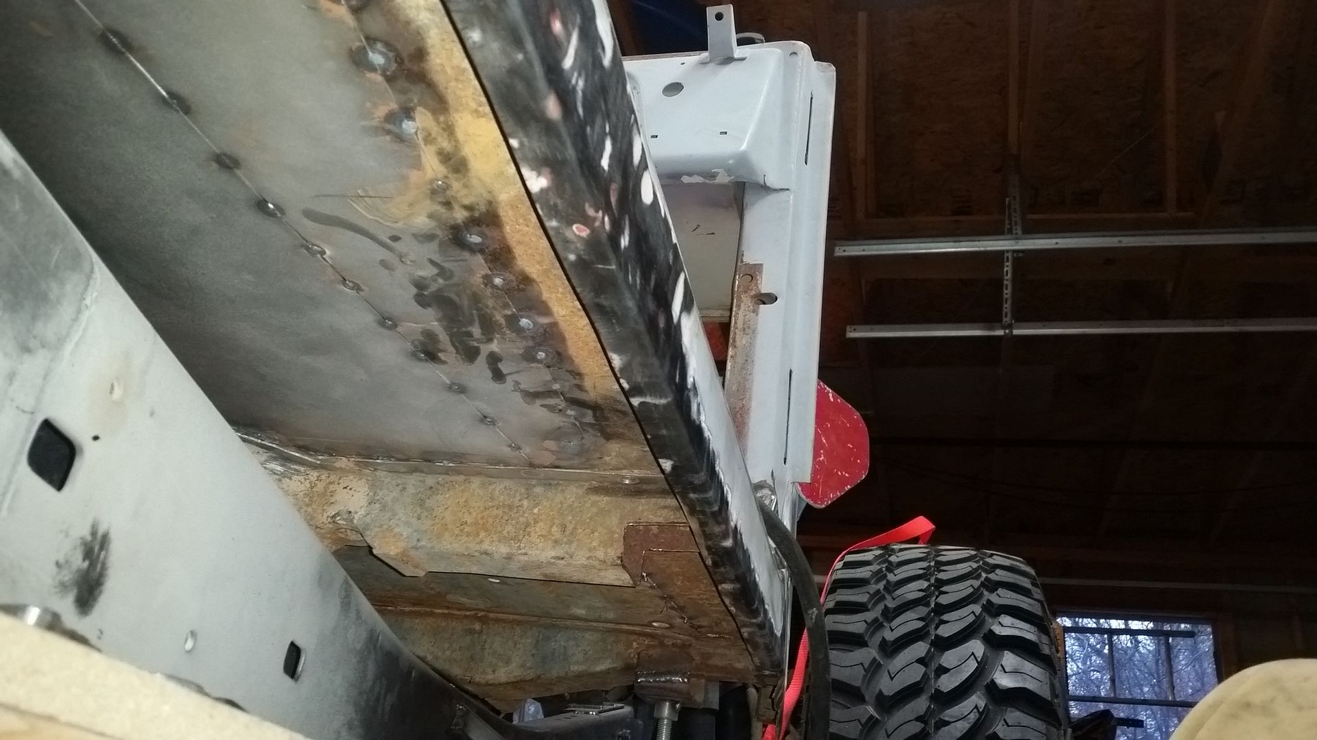
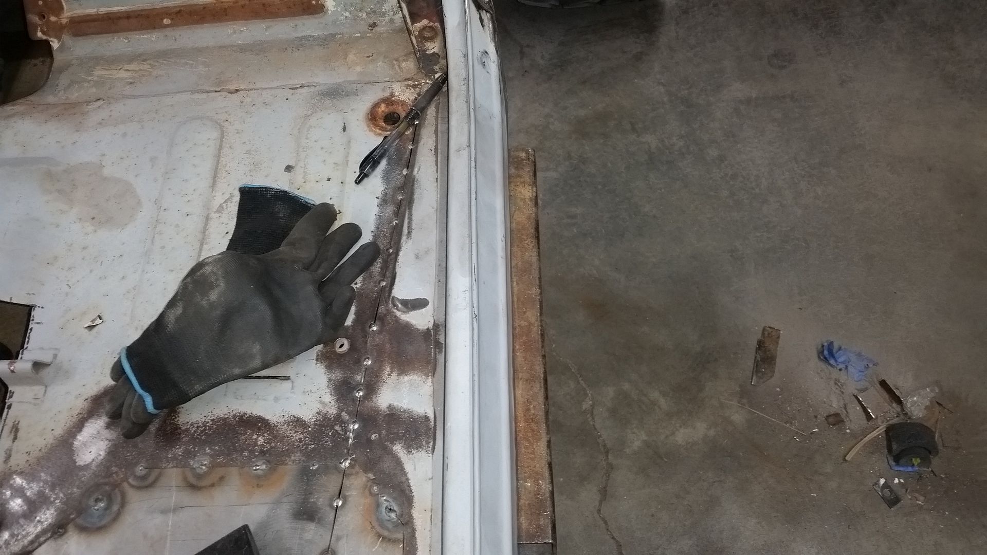
This is what the final flange ended up looking like. Overall it really wasn't to bad to form. The 'bendy stick' tool ended up working very well. It has a little bit of a learning curve. It definitely works better on a complete panel on the vehicle. It does take about 9-10 passes to make a 90 degree flange....


You can watch the angle of the 'bendy stick' I progressed through the bending process. I also made a pass along the flange with a body hammer to crisp up the bend a little bit.

As far as I can tell the bend has the same profile as the stock bend.

Next I moved onto mocking up the position of the future rocker tube...


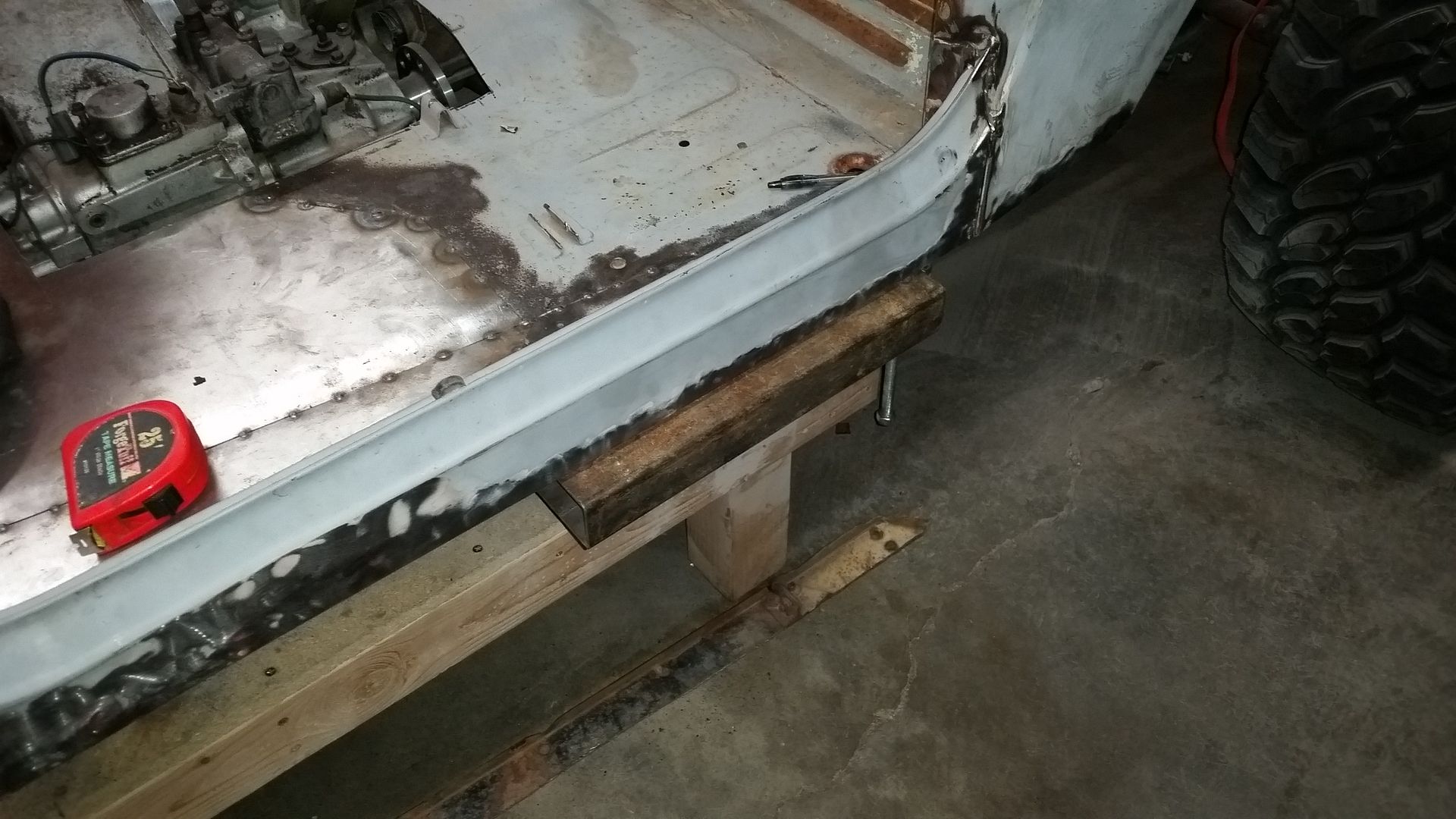
This is with 3x2 tubing, I will be using 3/16 wall for the final product. This short cut I had laying around is 1/8" wall I think. The corner radius on the thicker will be slightly softer.

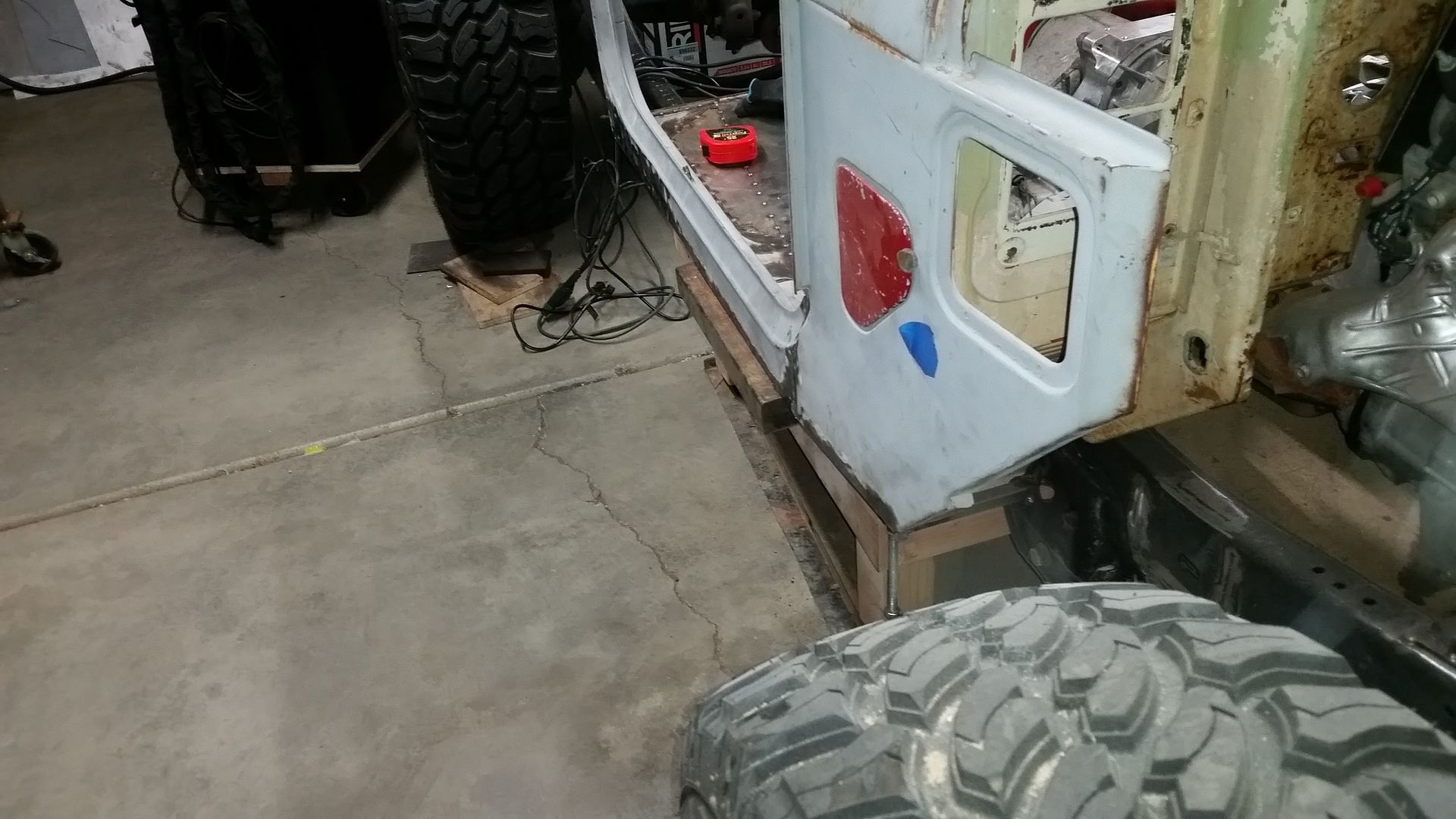
This mock-up is with a 1" offset from the body. I think that will be a nice balance. It should be enough to keep things off the body, but not so much as to get in the way. I hate it when you ********** your shin, or mud up your pant leg, when you entry or exit the vehicle. It also isn't big enough to be tempted to use it as a step. I think that is a good thing. I'm not a fan of jumping on the rocker tube honestly. I think I may add a step on the back of the rocker just past the cab. I am going built in about 1/4" of clearance between the rocker tube and the body. This should prevent the body from contacting the rocker panel when the chassis flexes.

I am looking for some ideas on what to do with the rocker in general. How to terminate the ends? How perhaps to use the space inside the rocker for storage? I was also thinking about perhaps adding some hidden recovery points to the outriggers. Sometimes I think it would be nice to be able to hold the vehicle from the side when doing a complex recovery.
 

Metcalf

Expedition Leader
Some weekend progress....


I trimmed, and flanged, the drivers side rocker panel to match the work done on the passenger side. Overall that process ended up working very well for me. In the end I think it looks very factory. I found some bondo in a few places that will need to be redone, but it's not a huge amount.


Once the rockers where all trimmed I figured it was time to pull this thing off the table. To my surprise the engine didn't fall out or anything! The totally flat belly sure looks nice. I wanted to get the chassis leveled back up once the weight was on the tires. I ended up needing a 1.5" shim under the front tires to get things to sit level.


Make the noise.....


I tacked in a few box tube outriggers to help temporarily hole the rocker tubes in position. Having the belly be totally flat really helped out with that under the front part of the frame.


Here is where I stopped for the night. I cut a 60" long section of the 2x2x3/16" box tube I am using for the rocker tubes. It ended up working out that I needed a 5" tall spacer from the bottom of the frame (temp outrigger) to the bottom of the rocker tube. This ended up working pretty well really. The temp outrigger lets me position the rocker tube easily compared to the body and frame. Everything is level to the belly section of the frame. I can dial in the position of everything and then tack weld, of clamp, it all in place before building anything to connect to the frame.
 

Metcalf

Expedition Leader
Just building a few tools tonight....


I had drilled/tapped my welding table a few months back in a 6x6 grid pattern in 3/8-16 thread.

I finally got around to building some clamps to use with that feature. I wanted something affordable that was easy to make. I basically ended up buying some clamps from Harbor Freight and modifying them to work like I wanted.....

http://www.harborfreight.com/6-inch-bar-clamp-96210.html

These clamps where about $3 each.

I cut off the fixed end of the clamp and TIG welded on a short 3/8" bolt.

The clamps have enough depth to reach half way across the grid pattern also. That gives me a lot of flexibility in where I can space things on the table when building assemblies. Now I can basically add a clamp anywhere on the full 4x8 surface of the table.

Overall, for less than $5 a clamp I am pretty happy. I think I have enough to build about 10 units. I got 4 done after work tonight. I will build the others soon.

I have a few things coming up on the new project that this will be handy for....
 

Metcalf

Expedition Leader
Tonight's progress....


I stuck the hood and windshield back on the body. I needed to get some measurements with the windshield in place to plan the B-pillar and halo. It is also nice to double check the position of the hood and engine.

Running at tape measure around the body a few times, boy it would be nice to have a complete stock FJ40 to measure. It doesn't matter that much, and I tend to overthink things, but knowing what 'stock' was would be nice. Oh well. I will muddle through it.


I made some super fancy high tech drawings to help plan things out for the top structure.....super fancy.....

I am going to try and lower the 'top' of the door slightly from stock and 'pull down' the future top panel compared to what I can see in stock pictures. This should help reduce the overall height a bit without having to chop down the windshield.

It also looks like my idea to have the rear window panels un-bolt and store in the bottom part of the body should work out! I have to raise the belt-line of the tub about 2.25" but I don't think that will be too noticeable. It will actually help me have a little extra vertical height for the bed which I think will help with the fenders and bed rail....


I let the saw cut some material for the B-pillar and spreader that will be at floor level. I need to miter some of the ends so I can weld it into a big U-shape.


While I was waiting for the saw to cut everything, I finished up the set of table clamps I as making. I now have a set of 10. That should be handy for laying out the B-pillar, halo, beltline tube, etc....

Fun stuff!
 

Metcalf

Expedition Leader
Just a little bit tonight, I am fighting off some kind of genetically engineered super flu that has been going around the office....ugh.


Trimmed and capped the rocker bars. I have been working on my TIG welding a bit. Practice practice practice. I actually got a 'free' huge bottle of argon to use up this month from work. We are changing suppliers and they didn't want to return a bunch of gas for 'free'. Small win for me.


I was able to finish one side before my head felt like it was going to explode like an alien wanted out. I cut the front of the rocker to 45 degrees to match the fender angle and fancy things up a bit for no particular reason.


While I was welding I let the bandsaw chew on the tubing for the B-pillar and a spreader at floor level. I will be welding these parts into a big U-shape. I needed to miter the ends for the corner junctions.


I also took another look at the position of the body. I had been questioning myself on how tall the body looks at full bump. My perception on that are pretty screwy after building my flat fender. That thing sits so low it's silly. The new truck just seems tall.

I have done some fishing around for some 'stock' measurements for an FJ40 to compare to. Near as I can tell, this thing sits about the same height at full bump as a stock FJ40 does at ride height. Stock tires on an 40 series are about 28" tall. I am running 40" tires. That means that I can add approx 6" of uptravel and still maintain a near 'stock' overall relative height. That makes me pretty happy.....but it still seems tall. I think the stock FJ40 is just a taller vehicle.

Short version. If I bolted 40" tires on a stock FJ40 it would about as tall as mine hybrid is going to be.
 

Metcalf

Expedition Leader
How about a front suck down winch?


I am thinking about sticking it on the original passenger side motor mounts pad. That mount is well built and perfectly formed around the front axle. It would also put the line in the correct path and location on the front axle housing.

Use this little winch....

http://www.amazon.com/Superwinch-11...UTF8&qid=1460654102&sr=8-1&keywords=ATV+winch

I would change the line over to some 3/8" synthetic line for durability. It would only need less than 10 feet of line. Then weld something to the front axle to direct the line to the opposite frame rail under the crank pulley. I just have enough space for that.

Thoughts?
 

Metcalf

Expedition Leader
Trying to keep my progress going last night...


I welded the caps on the second rocker bar and got it roughed into position. I also raised the body about another about 1/8" to account for bushing deflection in the body mounts and hole tolerance.....and just leveled the body to the rocker bars, which are level to the bottom on the frame.


I started laying out the B-pillar sub assembly on the table. Yes, I am using square tubing for some of the cage. Since the cabin area is going to be on the small size since the body is only about 56" wide, I didn't want an obtrusive separate 'cage' taking up space. I decided that I wanted to use the structure for multiple purposes. It will not only provide some protection from a roll over for the occupants, it will also define a lot of the lines of the body along with provide something to hang the body panels off of. The lower back panels below the belt-line of the body will be fresh 16 gauge sheetmetal that will be welded in place and mate up to the existing body. All the top panels will be bolting to this new stucture. That will include the windshield frame, top panel, and rear upper window panels. I guess you could think of it as an semi-hidden exo-cage.

The B-pillar is 2x2x0.12 wall tubing. That structure will be a big U-shape with a full side to side spreader at floor level. It will will also contain the mounting flanges for the rear body mounts. This structure will basically be right behind the existing door post.

The majority of the rest of this structure will be 1.5x1.5x.12 square tubing with a few mandrel bends to form the shape of the rear corners. The A-pillars will be 1.5x.12 DOM tubing along with the spreader bar at the top of the windshield....which will be rolled to match that shape. I will also have to do a little additional weld on sheetmetal work to form the upper part of the door surrounds.


I guess my saw needs a little fine tuning at the 45 degree cut setting. I aligned the tubes using a large square....this was the resulting gap. Not terrible, but will require a little adjustment. to fit correctly for welding. The new clamp system for the table is SOOO nice. You can leave the clamps just snug and still tap things around. Once in position you can really crank them down and stuff doesn't want to move at all.

Fun stuff. I will continue working towards getting the body mounted to the frame.....sadly I can see that taking a few more weeks to build all the supporting structures. I am really curious to see the shape of the body tub start to emerge. I think it will really help define the shape of the vehicle.
 

Metcalf

Expedition Leader
I didn't get to much this weekend on the new truck, I got looped into helping some friends move.....guy with the big truck and all that.

Anyhow. I spent most of my free time measuring a lot of stuff on the suspension. I was very curious to find out what the un-sprung weight was currently since I have all the springs out.

I saw some cheap 400lb bathroom scales on Amazon and figured I would give it a try.....


It was a good thing that I ordered two scales. My original idea was to stick a scale under each tire, but that didn't end up working out. I ended up having the corner weight pushing 400+ at each corner.

I found, through some trial and error, that the chassis needed to be near ride height to prevent any bind on the stock suspension arm bushings that may have an effect on the weight.


This is how I pulled all the chassis weight off of the axles with the engine hoist. I also found that the axle needed to be very level of the numbers would be very messed up by the sway-bar on the rear suspension and the sway/bind function of the front radius arms.

The final numbers where.....

RF 380 / LF 404
RR 402 / LR 383

I found it curious how close all the numbers where. I still have some doubts, but I think it should be in the ballpark at least. I have a 2000lb hanging scale coming and will run some of this again in a different way.

I also pulled one of the tires/wheels and weighed it. The tire and wheel combo was 137lbs.

If you subtract the tire/wheel weight from the un-sprung weight you end up with....

Front- 510lbs
Rear- 511lbs

Overall I find those numbers a little too close and convent, but I checked myself multiple times in separate sessions with some lunch time to ponder things.

The remaining un-sprung weight would contain the axle assembly and in theory 1/2 the weight of the suspension links, all the weight of the shocks, steering tie rod, steering arms, brakes,1/2 the steering drag link, etc. I checked to see if the shocks had any gas charge and could not detect anything and was able to move the shocks by hand.

510lbs for the front and rear axle/suspension/steering sprung weight strikes me as a bit odd, but I can't find anything that stands out as off.

The 1st time I tried to so this, I made the mistake of not having the axle level when weighing things. That causes some 'bind' in the swaybar system which has a large effect on the numbers for sure. I went back in the 2nd session and made sure the opposite tire was at the same level as the scale side.

Overall I find it interesting and a bit interesting to think about.
 

Metcalf

Expedition Leader
I also took a large number of suspension measurements for the spring and shock mounts.

Front suspension.
-7.5" coil height in chassis at full metal bump
-17" shock mounting compressed length , to stem/stem style mount flats
-20.25" Drivers spring free length
-19.5" Passenger spring free length

Rear Suspension.
-7.75" coil height in chassis at full bump
-16.5" shock mounting compressed length, eye bottom to stem top surface
-18.5" Drivers spring free length
-18.0" Passenger spring free length

That tells me the stock front coils have 12" of travel. The rear coils have about 10.25" of travel. Those numbers will maintain the coil in the mounts. You would still have to have a shock with enough travel. I will need to take a careful look at what shocks will fit. It would be really nice to have about an 11" shock in the chassis. I have a few ideas how I might add a little bit more rear suspension up-travel by relocating an upper shock mount cup and changing the outer rubber bump pad for a shorter unit.

On the rear suspension, There is a large diameter tall inner bumpstop of the rear suspension. It is 6" tall. At full bump, when the outer solid rubber stop engages there is only 3.5" of space for the inner bumpstop. That means that inner unit compresses 2.5" before the axle stops on the outer part. I have to wonder if the large inner units are some kind of progressive rate overload feature?
 

locrwln

Expedition Leader
Metcalf;2070226 I have to wonder if the large inner units are some kind of progressive rate overload feature?[/QUOTE said:
Yes they are. They work pretty well on an 80, but not sure about for your needs. I removed them and used air bags for my loaded 80 to deal with the extra and varied loads that it carried.
.
Jack
 

Metcalf

Expedition Leader
More fun with scales...


http://www.amazon.com/Sun-king-prec...&redirect=true&ref_=oh_aui_detailpage_o00_s00

$133, 2000lb scale

Front sprung is 876
Front total is 1508
Front un-sprung would be 632
Minus tire and wheels (137x2=274) would be 358 axle and suspension weight.

Rear sprung is 610
Rear total is 1375
Rear un-sprung would be 765(?)
Minus tire and wheels (137x2=274) would be 491 axle and suspension weight.

Total weight would be 2883 so far.


Front sprung


Front total


Rear sprung


Rear total
 

Metcalf

Expedition Leader
Ok.....one last time to find some weights! I should really be building but this is so annoying I had to get some numbers I had some faith in.

This time I busted out the big guns and brought home some certified wheel scales from work!


The weights from this method of measuring are as follows....

2840 Total

Front-
1660 total
880 drivers side
780 passenger side
640 unsprung ( front axle, suspension, steering would be 366 )
1020 sprung

Rear-
1180 total
560 drivers side
620 passenger side
620 unsprung ( rear axle, suspension would be 346 )
540 sprung

Tire and wheel is still 137lbs

I think these numbers are the best so far. These scales are meant for much higher weights, but should be accurate enough.

Ok....back to building now.
 
Last edited:

Metcalf

Expedition Leader
Trying to get back at it....


I finished making the main B-pillar U-structure. This is the 1st part for the cage structure. The small tube at the top is just a temp fill to keep everything square, I had some slight pulling from the welding which needed to be managed.

This structure will do a few things. It provides the B-pillar vertical. That will basically form the back of the door surround also. The rear body mounts will be tied into the lower corners. I decided to add the full floor width spreader bar also. That will provide a strong base for the rear of the seat mounts. This will all be welded into the body structure when finished. This structure is all 2x2x1/8 square tube.

Next up are templates for the inside of the rear body mounts. I am going to pattern them up in the vehicle, tack, and pull it to weld in those brackets. They will also act as gussets for the rear lower corners. Once those brackets are done I can tack the assembly in the vehicle in the final position and move onto the rear body mounts which are integrated into the rocker bar outriggers.
 

Forum statistics

Threads
186,037
Messages
2,881,238
Members
225,705
Latest member
Smudge12
Top