Be cautious ordering generic blue wrap LFP cells

hour

Observer
Well.. I feel kind of bad.

Either I have too much crap on my battery terminals (specifically the + and - of the overall pack) or I had a cancerous balance harness in the system.

Summary: I have two sets of balance leads. One goes to the charger, the other to the equalizer. That means two connections on pack + and - by default.

Add in a third ring terminal that goes to the BMV shunt on the pack negative.

Add a third and fourth ring terminal on the pack positive for charge inlet, and a positive lead to a fuse block which I discharge through.

In short, that's a lot of crap on the terminals. I slimmed it down, removed equalizer harness, and am now charging at 29.5 amps (410w) with 42mV difference. No longer is cell 3 shooting up to 3.6v the second it gets charge put on it. The problem was in my ring terminal fiasco or a dookie harness throwing things off. That cell is not wrecked like thought on last page. Things look good. This has likely been affecting a whole lot of my testing, because on most of them where I wasn't using the equalizer, I simply unplugged it. But its ring terminal bulk + harness presence was still there.

I think I'll always have two complete balance harnesses connected, one for a BMS and one for external monitoring and connecting to balance charger. That's 2 rings on every terminal - on every cell - of the battery, always. On pack negative I'll always have a third run to my BMV shunt. On pack positive (once I re-integrate), I'll always have a third run to my BatteryProtect, and another run for temp sensor + BMV positive. I guess to prevent even more crap on the pack terminals I can stack charge + on the BatteryProtect inlet, and then all the output will go to the output side of the BP.

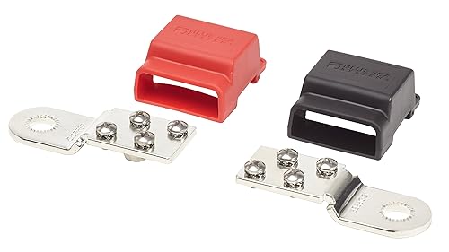
Is this sufficient for connecting to battery main + and -, and then attaching applicable (2 per) balance leads, or will that impact accuracy? I'm finding this needs to be the best connection possible or I have freak outs like last night, and it's certainly no good for meaningful BMS protection and balance charging if squirrely.

71DF7hCEbZL._SL500_.jpg

balancefixed.jpg
 
Last edited:

luthj

Engineer In Residence
Are you following the current rule for stacking the terminals? Highest current on the bottom? A torque wrench for the nuts can't hurt either. You need to make sure the terminals are nice and flat, high quality units. More contact area is better.
 

hour

Observer
Are you following the current rule for stacking the terminals? Highest current on the bottom? A torque wrench for the nuts can't hurt either. You need to make sure the terminals are nice and flat, high quality units. More contact area is better.

They're tightened with a socket extension + socket in the hand (significantly more than finger tight directly on the nut), not using a wrench. I didn't want to damage the battery internally by going too wild - and I've been removing them somewhat regularly in this process. I'll snug them down using the actual wrench now.

With regards to the stacking, even now after removing a harness and rearranging - no. The BMV's temperature sensor & positive lead is enormous and has to go on the bottom. Otherwise, yes. I have the balance connectors for main + and - on the top of actual charge and discharge leads.

I think with the BlueSea terminal bus bar I posted above, I could connect the BMV temp & + connection to the stud. It's too big to fit on those four little screws. But everything else could go on those 4 other ones.. That'd limit me to probably 10awg wire going to my fuse block, and to my battery protect. I'd like to go bigger, so maybe I'll connect them directly to the studs too and on the positive side put the BMV temp stacked. That damn thing though, huge rectangular lug..
 

hour

Observer
PRAISE!

I discharged 104 or so amp hours today and monitored remotely from work with the security camera aimed at the BMV712 display unit and an RC cell monitor to watch lowest cell voltage. This was connected to a wifi-controlled power strip so I could toggle outlets on and off and pull anywhere between 20w and 200something watts switching outlets on or off from my office.

So, this was my first big charge on the iCharger X6 and Meanwell 600w PSU. I corrected the balance lead issues in my post above, and began throwing 410whatever watts at it.

The charger just began to throttle a few minutes ago and has reduced to 3 amps down from 29.5. BMV shows I have 1ah to go until I'm fully charged. iCharger display shows 102.95ah put in over 3 hours and 38 minutes.

This is just freakin' dandy. The pack took a fat charge to 3.6Vpc and throttled when needed, only at the very end. Makes me think top balancing has held, and this is going to work out wonderfully. I'll do another discharge and then charge to 3.45Vpc to mimic my solar settings. Then see what I can pull out as a whole, set that on my BMV, and throw the ********** in an ammo can.

3H 52M charge time, just dinged to tell me done. Finished at 6mV balance. I think it'll continue to balance, not really sure with the X6 charger. This went spectacularly.
 
Last edited:

hour

Observer
Final update on this before I create a build thread as I'm throwing it in to an ammo can. This will include all the stuff learned from this thread including getting a custom pack in to operation and will be the steps I follow to a T on my next build. Yeah, there will definitely be another as I scope out rural property for a SHTF/cabin deal.

I'm a dipsh!t, balance leads or ring terminal fuvkfest caused issues, a lot of these posts wouldn't exist had I known that was my culprit.

Pack charged up in above post and I got it to end balancing at 1mV. So, it's time to discharge and see if I'm still observing a 200mV difference on one cell, indicating it was borked.

Now hitting it with 270w load and i'm floating between 5mV and 15mV imbalance. This is almost 4x the average load I'll have on the pack. Everything is staying tight. If I switch off load it jumps back to 1-2mV difference instantly.

I'll see after many hours and 100+ Ah taken how balanced things are under that sustained load, and when cutting load.

I'll charge up to 3.45Vpc after this, discharge again until I'm content with what I've pulled or a cell starts indicating it's gonna go weird on the low end. That'll be my configured pack size on the Victron BMV.

Thanks for sticking with me.
 

shade

Well-known member

hour

Observer
61bPFS6r5qL._SL500_.jpg


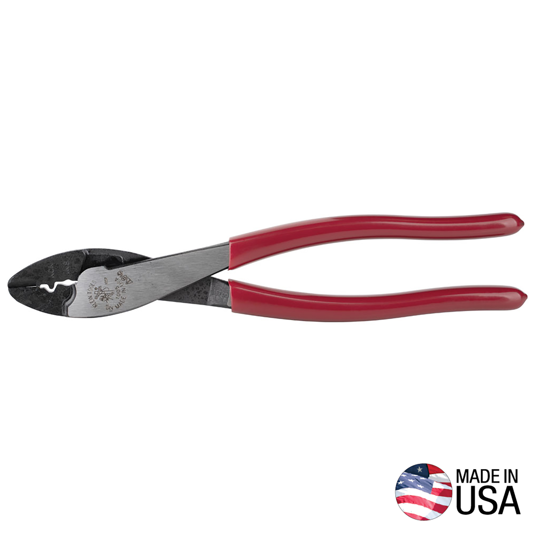
One from amazon a few years ago. Works a lot better than the $8 yellow or red handled ones you can get anywhere. Makes a solid square indentation in crimp ends. Strips most wire pretty well, softer jacketed stuff sometimes struggles but for the super flexible silicone stuff I've found it best to use an X-acto/razor blade. Hold on table and roll wire forward and backwards, then use teeth to pull it off with ease, zero loss of wires. This one can mangle soft stuff on occasion. Dedicated tool for Anderson PowerPoles.

When I built my portable packs using batteryblocs they came with quite a few uninsulated ring terminals. I almost like those better and should probably try to find a bag of 100 online. Easy to crimp, add solder if you want, and then slide heat shrink over the whole shebang. Perfect for balance leads.

21Ah discharged so far @ 260w / 20.0A. Averaging 11mV difference ?
 

luthj

Engineer In Residence
That the combination crimper and stripper is fine for uninsulated terminals, but do not use it to crimp insulated style terminals. Those should have a flatter die ratcheting type crimper.
 
Last edited:

Alloy

Well-known member
I tried allot of wire crimpers. Found ratcheting double crimp to be too wide or dies don't compress 18-20ga connectors enough.

I always have my Kleins if I'm not crimping with then I'm cutting wire. Cutting wire with ratcheting crimpers is time consuming.


Alloy

Well-known member
Soldering is a no no....if a crimp is done properly there is no room for solder and no reason to have flux run 2"-3" up into the wire so it keeps corroding the wire for years.
 

Alloy

Well-known member
These are the wire strippers I use. If I'm stripping 18ga I use the slot for 16ga and so on. On 10ga l make 2-3 cuts in the insulation.


hour

Observer
Soldering is a no no....if a crimp is done properly there is no room for solder and no reason to have flux run 2"-3" up into the wire so it keeps corroding the wire for years.

Good to know, I've done it for large battery lugs (blow torch, fill cup with solder, insert 2 gauge wire, hammer crimp quickly) think I saw that somewhere on youtube and it made sense given that my hammer crimps weren't always precise. I did it for the small uninsulated balance leads on the portable packs I built just to get the tiny bit of wire poking out of the tunnel on to the surface of the ring terminal flat. I'll just up my crimper game and get something ratcheting. If I did more large battery cables I'd throw the hammer crimper in the trash and get a hydraulic one.

I charged the pack up to 3.45Vpc last night and then started a discharge @ 20 amps before going to bed. It's still going, 170ah consumed. Under this constant load and with 170ah taken, the cells are fluctuating between 10-15mV difference. If I flip off the load they go back to 1-3mV. Cells all reading 3.15v with load and at this low SOC. Would assume the seller claims of capacity are accurate but I don't want to push it and have to watch the cell monitor like a hawk. Also would never draw 170ah in service so i'll conclude this discharge momentarily. Pretty thrilled right now. The BlueSea terminal mount bus bars will be here Saturday, the last thing I need to complete assembly in to its ammo can home.

Only thing I might add if I can find something of quality, are adhesive backed 12v heat strips. Use load output on charge controller to operate a 12v temperature controller that powers the heat strips below 45*F. That'll keep it warm and capable of accepting charge this winter and I can't assume heating a near sealed ammo can would require a ton of power even with ambient temps well below freezing.

While that'd respect the battery by operating in configured boundaries of the load output, I think it'd also make the heater operate at midnight when it doesn't need to. Maybe I can add something between load output and the thermostat, like a light sensor. If bed of truck is pitch black, don't bother heating it. That might cause some delay in charge kicking on in the morning (sense light, work for an hour to get the box up to temp when it could be charging had it been warming earlier) but worth a test. Any ideas?
 

luthj

Engineer In Residence
Take a look at silicone heating pads, they are sometimes used for heating 3d printer base tables. You could wire two in series for about 90W of heat or so.
 
Last edited:

Forum statistics

Threads
189,875
Messages
2,921,751
Members
233,084
Latest member
Off Road Vagabond
Top