2022 Ford F550 - DIY - Adventure Expedition Vehicle Build Thread

Vance Vanz

Well-known member
Flex Testing – With CF Floor – In the Field:

It was nice to finally get out into the wild and do some real world testing on this beast, not to mention seeing your own handy work in action ?. It was also an opportunity to hang out with a life-long friend while doing it all.

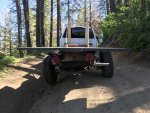
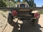
The first few pics are us just taking a pulse on the sub frame and floor while on a steep grade with a few deeper ruts.

IMG_7438.jpegIMG_7439.jpegIMG_7440.jpeg

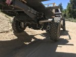
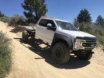
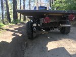
The next two pics were us starting to really test the subframes ability. In these two photos the left front tire and right rear tire are on the ground and the right front and left rear tires are off the ground. You can see the rear pivot doing its job and how level the floor remains. I've seen three and four point frames in action before, but it is always impressive to see how well such a simple design performs.
IMG_7436.jpegIMG_7435.jpeg

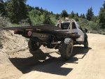
Here are more photos of us testing various aspects.
IMG_7449.jpegIMG_7451.jpegIMG_7452.jpegIMG_7453.jpegIMG_7455.jpeg

The great news is everything worked flawlessly and was right on spec. The height off of the chassis frame, rear pivot bump stop height, cab over clearance and cut-in floor box clearances are all good to go. It's now time to start building floor boxes and walls. Simple right ??

I also have some videos that I may post, but I'm not sure if I have the time, or want to get tied up in posting videos as well. We'll see.
 

Alloy

Well-known member
Floor Fitment to Sub Frame:

I know it doesn’t look like much in the grand scheme of the entire build, but getting the floor onto the sub frame was a mini-milestone for me, something to CELEBRATE! I told myself I would acknowledge and celebrate the intermediary milestones along the way. If not, this thing could just become one relentless and exhausting grind.

Sooooo, HELLZ YAHZ, my floor is on the sub frame! Visual progress is always welcome and needed on a project like this, such a motivator for me.
View attachment 728725View attachment 728726View attachment 728727

I was also able to drill and tap the flat bar steel imbedded in the floor, for all of the ½” grade eight fine thread bolts that hold the camper to the sub frame, twelve in total. (I chose fine thread over coarse for the slight bump in strength and being better for vibration.) All of the drilling and tapping went smoothly and the holes lined up perfectly. I also installed temporary 1” plywood spacers in-between the subframe and C.F. floor for final flex testing and clearance checks. These will be replaced with rubber pads once everything is finalized.
View attachment 728728View attachment 728730View attachment 728729View attachment 728731

I was also very pleased with how structurally solid the floor was by itself, without any cut-in boxes or walls attached. This thing will be bomber once it gets walls and floor boxes.


Excellent work!!

Really like the low profile design and fab of the under mount. I'm wondering if there will be something done internally to transfer the forces from the back mount to the outside walls?

Is the truck a 179" or 203" wheel base? How long is floor and the frame extension
 

Vance Vanz

Well-known member
Excellent work!!

Really like the low profile design and fab of the under mount. I'm wondering if there will be something done internally to transfer the forces from the back mount to the outside walls?

Is the truck a 179" or 203" wheel base? How long is floor and the frame extension
Thanks for the positive feedback Alloy!

I think I understand your question. If I'm off, just let me know. In the floor layup, there are four pieces of flat bar steel that span the entire width of the floor. Two of them sit right on top of the two front fixed mounts and two right on top of the rear pivot. You could say they perform a few functions 1. to drill and tap to mount the camper to the sub frame and 2. to help support the weight of the walls on the outside edges of the floor. Whether we are talking about distributing the support of weight, or force, it's kind of the same thing. I also have specific areas/fields within the foam core of the floor where vertical holes were drilled and then filled with epoxy. These epoxy filled holes act as vertical supports between the top and bottom layer of marine grade plywood. These areas/fields of epoxy filled vertical columns also span the entire width of the floor and are located above/around the subframe mounting points and in a couple of other key areas of the floor.

203" wheel base, 13'-1"L floor and 2'-4 7/16"L frame extension to be exact ?. The front of the camper will sit 2.5" off of the back side of the cab.
 

Alloy

Well-known member
Thanks for the positive feedback Alloy!

I think I understand your question. If I'm off, just let me know. In the floor layup, there are four pieces of flat bar steel that span the entire width of the floor. Two of them sit right on top of the two front fixed mounts and two right on top of the rear pivot. You could say they perform a few functions 1. to drill and tap to mount the camper to the sub frame and 2. to help support the weight of the walls on the outside edges of the floor. Whether we are talking about distributing the support of weight, or force, it's kind of the same thing. I also have specific areas/fields within the foam core of the floor where vertical holes were drilled and then filled with epoxy. These epoxy filled holes act as vertical supports between the top and bottom layer of marine grade plywood. These areas/fields of epoxy filled vertical columns also span the entire width of the floor and are located above/around the subframe mounting points and in a couple of other key areas of the floor.

203" wheel base, 13'-1"L floor and 2'-4 7/16"L frame extension to be exact ?. The front of the camper will sit 2.5" off of the back side of the cab.

HA! 2'-4 7/16"......that's why I like millimeters.

Looking at post #20 I didn't see the flatbar at the edge of the floor panel. I was wondering if they run front to back or side to side.

The front mounts are close to the sides/corner so the floor will be rigid there. It's the back mount I'm wondering about. I wouldn't have confidence in the loads being transfer from the outside edges to the center mount through the flat bar/foam. I'm guessing the back mount will carry 60-80% of the weight. Piling weight on the back corners of the floor panel to check the side to side deflection over the mount will tell if the flat bars are working.
 

rruff

Explorer
It's the back mount I'm wondering about. I wouldn't have confidence in the loads being transfer from the outside edges to the center mount through the flat bar/foam. I'm guessing the back mount will carry 60-80% of the weight. Piling weight on the back corners of the floor panel to check the side to side deflection over the mount will tell if the flat bars are working.

I'm interested in details of how the steel is fitted as well. This a complex structure with plywood, steel (I think?), and carbon in the "skins" and a foam core, so kinda hard to analyze.

When different materials are combined in the skins, the stiffness and strength properties of each are particularly important. For instance since carbon is roughly 3x stiffer than FG and only slightly stronger, if you combine these two in a skin, then the carbon is carrying most of the load, and will be the first to fail. A "pretty" carbon layer on top of a FG layup would be a disaster, for instance... much weaker than the FG layup alone. That's why earlier I was curious how thick VV's carbon was and if it was enough to carry all the load, rather than just serve as a hard layer for the plywood... and I think that part will be fine.

My camper is smaller and much lighter with a similar support arrangement, and carbon skins... but I don't have anything in the core other than ~150 psi PVC foam, and epoxy columns under the supports (edges are wrapped). I was planning on FG or carbon "beams" under the mounting points that spanned the width, but then decided it was overkill. Time will tell, though. I will say that my floor/base is super stiff.
 

Doslocos

Member
Quick question about your tire/wheels. I have the same setup and am getting ready to install on my much older f550. Question is I was under the impression that the rears had to be mounted on reverse ( bead lock to the inside) to track correctly? Do you have a spacer on the rear? great project following Thanks
 

Vance Vanz

Well-known member
HA! 2'-4 7/16"......that's why I like millimeters.

Looking at post #20 I didn't see the flatbar at the edge of the floor panel. I was wondering if they run front to back or side to side.

The front mounts are close to the sides/corner so the floor will be rigid there. It's the back mount I'm wondering about. I wouldn't have confidence in the loads being transfer from the outside edges to the center mount through the flat bar/foam. I'm guessing the back mount will carry 60-80% of the weight. Piling weight on the back corners of the floor panel to check the side to side deflection over the mount will tell if the flat bars are working.
Hey Alloy!

That's what the online conversions are for ;)!

I held the flat bar in just a pinch so there would be some insulation separating it from the edge of the CF skin. This was done intentionally, as I am trying to prevent thermal bridging in every aspect of the build. This is an example of one of those small opportunities that is often not thought about or missed.

When you say loads, are you talking about the loads of just the walls of the camper on the outside edges of the floor, or the loads of what is in the camper that may sit towards the outside edges of the floor?

The walls of the camper are light, foam and carbon fiber skin. They hold up the roof, but again, the roof is also foam and carbon fiber skin, very light. It is not just the flat bar steel that is spanning the width of the floor over the rear pivot to hold up the weight of the walls. The CF is the more important thing to think about. The entire floor/core is wrapped, on all sides, with 33oz's of carbon fiber. This makes the entire floor structurally solid and this is what distributes structural weight across the entire floor/core, not just the outside edges. Not to mention there are also 2 layers of marine grade plywood inside the core that have all of their seems epoxied and CF'd top and bottom, which further distributes weight across the core/floor. My floor is arguably overbuilt. I can literally jump up and down on the outside edges of the floor, on each side of the rear pivot, and the floor does not flex or creek. When the boxes in the floor, wheel wells, exterior walls, interior walls, and cabinets, which are all composite CF, get CF'd to the floor and to each other, it will only further distribute the weight throughout the entire structure, not just the edges of the floor. This is the benefit of this type of construction.

A majority of the weight inside the camper will sit towards the front of the camper and sub frame. My water and all hot water/heating mechanical equipment sit right behind the cab on the passenger side and are partially supported by the front outrigger of the sub frame. My batteries and all electrical equipment also sit right behind the cab on the drivers side, inches from the front outrigger of the sub frame. Most of the water tank also sits below the level of the floor, as do all of the lithium batteries. The very rear of the camper, on top of and behind the rear pivot are the MTB locker, shower and entry way. Pretty much everything that weighs a lot is in front of the rear tires, not behind them.

Earth Roamer has spent years figuring all of this out and that is why I am modeling my build after them, so I don't have to reinvent the wheel and can trust that it will work. Just to be clear, I am not saying my build is exactly like Earth Roamers.

If I am misunderstanding something, just let me know.
 

Vance Vanz

Well-known member
I'm interested in details of how the steel is fitted as well. This a complex structure with plywood, steel (I think?), and carbon in the "skins" and a foam core, so kinda hard to analyze.

When different materials are combined in the skins, the stiffness and strength properties of each are particularly important. For instance since carbon is roughly 3x stiffer than FG and only slightly stronger, if you combine these two in a skin, then the carbon is carrying most of the load, and will be the first to fail. A "pretty" carbon layer on top of a FG layup would be a disaster, for instance... much weaker than the FG layup alone. That's why earlier I was curious how thick VV's carbon was and if it was enough to carry all the load, rather than just serve as a hard layer for the plywood... and I think that part will be fine.

My camper is smaller and much lighter with a similar support arrangement, and carbon skins... but I don't have anything in the core other than ~150 psi PVC foam, and epoxy columns under the supports (edges are wrapped). I was planning on FG or carbon "beams" under the mounting points that spanned the width, but then decided it was overkill. Time will tell, though. I will say that my floor/base is super stiff.

Hey rruff,

Yes, the thickness of CF I have chosen and the core material height, have a lot to do with the strength of the floor. The plywood and steel only help this. Heck, even my Divinycell foam is a higher rating than most use. I didn't do this intentionally, it just worked out that way because of supply chain shortages.

I was also going to run CF internal I beams in the foam core of the floor-in between the sheets of plywood. In the end I decided not to, as I have enough CF composite structures tying into other CF composite structures throughout the camper. This thing is only going to keep getting stronger every time I CF another box, wall or cabinet to the floor/structure.

If only I could finalize my camper design to start building some walls :confused:
 

Vance Vanz

Well-known member
Hey Alloy!

That's what the online conversions are for ;)!

I held the flat bar in just a pinch so there would be some insulation separating it from the edge of the CF skin. This was done intentionally, as I am trying to prevent thermal bridging in every aspect of the build. This is an example of one of those small opportunities that is often not thought about or missed.

When you say loads, are you talking about the loads of just the walls of the camper on the outside edges of the floor, or the loads of what is in the camper that may sit towards the outside edges of the floor?

The walls of the camper are light, foam and carbon fiber skin. They hold up the roof, but again, the roof is also foam and carbon fiber skin, very light. It is not just the flat bar steel that is spanning the width of the floor over the rear pivot to hold up the weight of the walls. The CF is the more important thing to think about. The entire floor/core is wrapped, on all sides, with 33oz's of carbon fiber. This makes the entire floor structurally solid and this is what distributes structural weight across the entire floor/core, not just the outside edges. Not to mention there are also 2 layers of marine grade plywood inside the core that have all of their seems epoxied and CF'd top and bottom, which further distributes weight across the core/floor. My floor is arguably overbuilt. I can literally jump up and down on the outside edges of the floor, on each side of the rear pivot, and the floor does not flex or creek. When the boxes in the floor, wheel wells, exterior walls, interior walls, and cabinets, which are all composite CF, get CF'd to the floor and to each other, it will only further distribute the weight throughout the entire structure, not just the edges of the floor. This is the benefit of this type of construction.

A majority of the weight inside the camper will sit towards the front of the camper and sub frame. My water and all hot water/heating mechanical equipment sit right behind the cab on the passenger side and are partially supported by the front outrigger of the sub frame. My batteries and all electrical equipment also sit right behind the cab on the drivers side, inches from the front outrigger of the sub frame. Most of the water tank also sits below the level of the floor, as do all of the lithium batteries. The very rear of the camper, on top of and behind the rear pivot are the MTB locker, shower and entry way. Pretty much everything that weighs a lot is in front of the rear tires, not behind them.

Earth Roamer has spent years figuring all of this out and that is why I am modeling my build after them, so I don't have to reinvent the wheel and can trust that it will work. Just to be clear, I am not saying my build is exactly like Earth Roamers.

If I am misunderstanding something, just let me know.

Hey Alloy,

I just thought of one more thing to add, related to my internal walls. My mountain bike locker walls, shower walls and another large cabinet wall, are all composite CF and nearly span the entire back width of the camper. All of these walls also go from the floor to the ceiling and act as vertical supports for the roof, while also tying the floor into the side-walls and roof.

Maybe when my trip is over and it is still fully insured, we can send it rolling off a cliff and see how she holds up ?
 

Vance Vanz

Well-known member
Quick question about your tire/wheels. I have the same setup and am getting ready to install on my much older f550. Question is I was under the impression that the rears had to be mounted on reverse ( bead lock to the inside) to track correctly? Do you have a spacer on the rear? great project following Thanks
Hey Doslocos!

Thanks for the kind words and for checking in.

Yes, spacers were added. I needed the front and rear wheels to be aesthetically the same. It would drive me nuts to have the rears flipped, but I'm a bit OCD.

DBL sells them, but they aren't cheap. I'm not sure who else may carry them.
 

rruff

Explorer
I held the flat bar in just a pinch so there would be some insulation separating it from the edge of the CF skin. This was done intentionally, as I am trying to prevent thermal bridging in every aspect of the build.

Some questions if you don't mind answering... Where exactly is the bar located in the cross-section? Is it above the lower layer of ply, between the ply and CF... or somewhere else? Is it attached with epoxy, something else, or floating? What are its dimensions?
 

Alloy

Well-known member
Hey Alloy,

I just thought of one more thing to add, related to my internal walls. My mountain bike locker walls, shower walls and another large cabinet wall, are all composite CF and nearly span the entire back width of the camper. All of these walls also go from the floor to the ceiling and act as vertical supports for the roof, while also tying the floor into the side-walls and roof.

Maybe when my trip is over and it is still fully insured, we can send it rolling off a cliff and see how she holds up ?

The walls (bulkhead) is what I was referring to as "something done internally"

It's the cycle loads of bouncing over a few thousand potholes I'm thinking will take more of a toll than rolling off the cliff.
 

Vance Vanz

Well-known member
Some questions if you don't mind answering... Where exactly is the bar located in the cross-section? Is it above the lower layer of ply, between the ply and CF... or somewhere else? Is it attached with epoxy, something else, or floating? What are its dimensions?
Hey rruff,

Posts 30, 34 and 48 should include all of the info to your questions. If I'm missing something let me know.
 

Forum statistics

Threads
188,039
Messages
2,901,534
Members
229,352
Latest member
Baartmanusa
Top