2022 Ford F550 - DIY - Adventure Expedition Vehicle Build Thread

Vance Vanz

Well-known member
The walls (bulkhead) is what I was referring to as "something done internally"

It's the cycle loads of bouncing over a few thousand potholes I'm thinking will take more of a toll than rolling off the cliff.
Hey Alloy,

I'm glad you mentioned bouncing and potholes, thousands of them! It is one thing that distinctly stood out to me when reading another build thread while conceptualizing my build. The gentlemen stated "the three and four point subframes are great for eliminating torsional flex, so are the rail on rail spring mounts. But, no one said anything about the thousands of miles of wash board roads in Central and South America that are going to rattle your camper and rig to death!" :oops:, ......... ?, ............ :geek:

In addition to the materials and layup methods chosen for the camper, which make it very stout, I also oversized the mounting surface areas on all three mounting points for the subframe. Every three point subframe I have seen on comparable cab overs, including ER's, have smaller surface areas than I decided to go with. I did this intentionally. I will also be installing 1" thick 60 durometer neoprene rubber pads on all three mounts. I chose rubber pads over polyurethane for this very reason, it is better at absorbing vibration and noise. I also have a thicker walled polyurethane pivot bushing, for the rear pivot, then most run on a three point subframe. Mine is used for the trailers on semi trucks. This was done primarily to handle higher load capacities, but it will also absorb vibration better than the thinner walled bushings.
 

rruff

Explorer
Posts 30 and 34 should include all of the info to your questions, and pics in 21. If I'm missing something let me know.

"3/8" x 1.5" A36 flat bar steel inlaid in the floor, front and back: I have two steel bars in the front and the back of the floor, a total of four, that basically span the entire width of the floor. They act as a large nut that spans the entire width of the floor and will be drilled and tapped from the bottom side of the floor in order to mount the camper. This also provides a thermal free mount for the camper, no bolts penetrating completely through the floor."

"...so the steel bars inlaid in the floor are compressed against plywood, as opposed to the bottom layer of CF skin, when the camper shell is tightened down to the subframe."

I think that will work fine. The bars aren't adding much to the bending strength or stiffness of the structure, but they'll give you a good place to mount storage boxes and stuff.
 

Alloy

Well-known member
Hey Alloy,

I'm glad you mentioned bouncing and potholes, thousands of them! It is one thing that distinctly stood out to me when reading another build thread while conceptualizing my build. The gentlemen stated "the three and four point subframes are great for eliminating torsional flex, so are the rail on rail spring mounts. But, no one said anything about the thousands of miles of wash board roads in Central and South America that are going to rattle your camper and rig to death!" :oops:, ......... ?, ............ :geek:

In addition to the materials and layup methods chosen for the camper, which make it very stout, I also oversized the mounting surface areas on all three mounting points for the subframe. Every three point subframe I have seen on comparable cab overs, including ER's, have smaller surface areas than I decided to go with. I did this intentionally. I will also be installing 1" thick 60 durometer neoprene rubber pads on all three mounts. I chose rubber pads over polyurethane for this very reason, it is better at absorbing vibration and noise. I also have a thicker walled polyurethane pivot bushing, for the rear pivot, then most run on a three point subframe. Mine is used for the trailers on semi trucks. This was done primarily to handle higher load capacities, but it will also absorb vibration better than the thinner walled bushings.


If the 60D neoprene is the full size of the mounting plates I don't think it will do much for vibration. Strips or rings will allow for cushioning but the lack of surface area might allow the box to shift causing the holes in CF/Plywood to elongate. Adding more bolts or keying the floor panel to the steel would prevent the side to side movement.
 

Vance Vanz

Well-known member
"3/8" x 1.5" A36 flat bar steel inlaid in the floor, front and back: I have two steel bars in the front and the back of the floor, a total of four, that basically span the entire width of the floor. They act as a large nut that spans the entire width of the floor and will be drilled and tapped from the bottom side of the floor in order to mount the camper. This also provides a thermal free mount for the camper, no bolts penetrating completely through the floor."

"...so the steel bars inlaid in the floor are compressed against plywood, as opposed to the bottom layer of CF skin, when the camper shell is tightened down to the subframe."

I think that will work fine. The bars aren't adding much to the bending strength or stiffness of the structure, but they'll give you a good place to mount storage boxes and stuff.
Yes Sir. I was originally going to shorten the length of the bars for the rear pivot, but decided to leave them long, so I could use them to attach the grey water tank on the drivers side. They probably won't be needed on the passenger side, but at least I know I have them if I do need a solid mounting point for something.
 

Vance Vanz

Well-known member
If the 60D neoprene is the full size of the mounting plates I don't think it will do much for vibration. Strips or rings will allow for cushioning but the lack of surface area might allow the box to shift causing the holes in CF/Plywood to elongate. Adding more bolts or keying the floor panel to the steel would prevent the side to side movement.
Thanks for the input.

They will be the full surface area of the pad. I'll take whatever vibration absorption they will give.
 

Vance Vanz

Well-known member
Camper Shell Architecture - The Details! & Humaness Check In:

(Humaness Check In:)

Hi All,

I hope you had a good 4th of July!

I promised myself that I would post to the build thread on a weekly basis, no matter how big or small the progress. Since this is my full-time project until it is complete, and I have an ambitious build schedule, there should be enough to report on a weekly basis. In my opinion, it is nice to see some of the details that go into the build process, as opposed to just updates of the final product or outcome of the process. I spend far more time thinking about how I’m going to do something (engineering/designing/planning) than I do actually building it. Also, I want to include how the process of a project like this is impacting me personally, as a human.

I’m realizing that building an expedition vehicle is the most comprehensive project that I have embarked on in my life. It’s not that any one piece is rocket science, but the number of parts/systems/trades that you are trying to, and needing to, seamlessly integrate into one cohesive outcome, and in the lightest version and smallest space possible, is complex and can be overwhelming. I have built and remodeled homes, rebuilt centrifugal chillers, built and ran successful businesses, obtained several degrees, traveled/lived abroad for extended periods of times, trained for and completed triathlons/endurance mountain bike races, healed the existential and infinite abyss of the human psyche, and nothing compares to this project.

A one-of-a-kind prototype build can be awesome, because the sky is the limit on how you can build it. You can do whatever you want; if you can dream it, you can build! But, there is the flip side to this, not having set/established parameters, and having to make thousands of decisions-literally thousands of decisions. Sometimes trying to figure out one simple measurement requires you to consider and figure out eight other things as well. This can become maddening at times ?.

This past week, the entire week, was one of those tape measuring, number crunching, head scratching, final decision-making weeks. The types of decisions that you don’t want to SCREW UP, because they will cost you a lot of money or time in rework-if you do miss something. CF, Divinycell foam and ProSet resins are not cheap. Actually, nothing is cheap on an expedition vehicle if you are trying to build it to marine grade-ish standards. So Yah, a low level of anxiety kicked up at times, even a tinge of overwhelm ??. There were also some late nights, where I had to pause things and come back to it/them in the morning with a fresh set of eyes. By the end of the week, I was even wondering what the heck I had been doing all week, or better said, what I wasn’t doing or accomplishing all week.

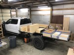
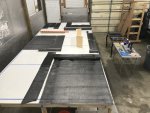
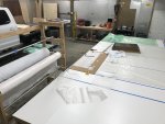
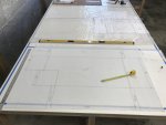
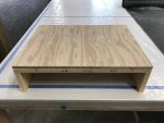
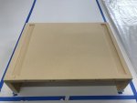
Visual progress seems to be the main sign of progress and if something is not visually changing on the truck/camper, it can start to wear on me. This reminds me, I wanted to share the hardest part of the build process, to date, for me. It took me two months longer than expected to find a shop to build the rig in. It was another three to four weeks of setting up the shop, building the CF layup table/material rack and ordering CF materials. Then there was another week of designing the subframe and another couple of weeks building a mock up floor, laying out all of the cut-ins for the floor and performing initial flex tests. All of this time and work so far, months, and when I looked over at the truck, it looked exactly like the day I picked it up. All of this was also present on top of the backdrop that I was already supposed to be a year and a half into my trip, as opposed to a year and a half delayed in the trip. (Previous van build by a shop going bad, COVID shutting down the trip, break up, having to start over related to a vehicle for the trip, etc.) as the reasons for the delay.

This began to wear on me, pretty bad at times. Low energy, internal questions starting to kick up, and a bit of doubt. There were even some of those flickers and moments when I asked myself if I actually wanted to build an expedition vehicle, or even go on this trip. These moments usually occurred when I needed to take a break, eat something, or take a day off, but none the less, they were present and strong at times. The answer to these questions and doubts after things settle down, was and always is “I want to go on this trip AND in an expedition vehicle with all of my adventure gear and creature comforts”. I have to tell myself “This is what you truly want. Build this damn thing the way you want; take the time to build it the way you want. It will all be worth it in the end. If you don’t, you will regret it!” This is why seeing the mini-milestones of the subframe on the truck and floor on the subframe were wins and much needed for my moral.


(Camper Shell Architecture – The Details!)
So, after a week of tape measuring, number crunching, head scratching and final decision-making, related to the camper shell design, in particular the cab over section and cut-in boxes on the floor, I’m ready to start more CF fabrication this week. Whooo Hoooo ?!

The dimensions given for my electric steps were off enough that I had to do a bit of redesign on the step-box for the floor. I’m glad I took the time to extended the electric steps and take my own measurements. If I didn’t, I would have been in a bit of a pickle after the fabrication of the step-box, if I had used the measurements given.

IMG_7489.jpeg

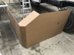
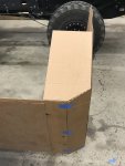
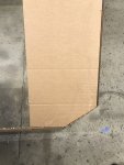
I also took the additional time to build a model of the cab over section, to scale out of cardboard, with everything located in its place. Given that I will be sleeping in this small area for at least two years, I wanted to make sure that it was what I wanted. Setting the height, and visual fields, given that there are four bunk windows, a sky light and a few custom angles, took a little time. Using CAD is helpful, but I wanted to have something to scale that I could actually lay down inside of and see/feel what it was going to be like.

I also did not want the camper shell to be just one squared off rectangle box with a 45-degree angle on the front of the cab over. I know this is the easiest for layup and fabrication, but I want to try and give this thing some shape, without killing myself on building molds, layup, fairing and sanding. I struck a subtle balance that will give the camper shell a little shape and match angles on the truck, while also keeping the fabrication and finish manageable for me. The nose of the cab over section, as well as the two front outside corners of the camper shell front wall-just behind the cab, will match the angles on the truck.

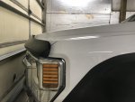
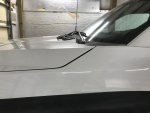
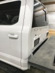
The front corners on the hood of the truck, from a top view and a side view, as well as the vertical corners of the back of the cab, are angular, at roughly or maybe exactly 33 degrees. The back of the camper will also have a drip leg and I may put a 33 degree angle coming off the bottom edge of it as well. If I have the time and I'm feeling spunky, I may also match the camper shell to the curvature on the the back side of the cab-where the cab starts to angle forward on the back window and rounds off on the top of the cab. These subtle angles on the camper, with the addition of four custom built fairings (that will mount to the bottom edge of the camper shell in front of and behind the tires and also match the lines on the rocker panels on the truck) should be enough to tie this thing together aesthetically.

Truck angles
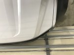
IMG_7504.jpegIMG_7506.jpegIMG_7502.jpegIMG_7507.jpeg

Cab over mock up and angles
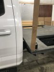
IMG_7509.jpegIMG_7500.jpegIMG_7508.jpegIMG_7511.jpeg

It’s not going to be an Earth Roamer or Truck House carbon fiber kinda looking shell, but it won’t be just a box on a truck.
 
Last edited:

Vance Vanz

Well-known member
rruff,

I thought of you during this weeks long process, how much time it must have taken you to get some of those sweet lines and curves on your camper shell all figured out.

Good for you (y), keep up the good work.
 
Last edited:

rruff

Explorer
I made the shapes in sketchup, which I don't know how to use very well. Still wasn't a perfect fit... kinda lumpy.

Based on what I've read, you can get most of the aero benefits by putting a generous radius on the edges. That's probably a lot easier and would give you more interior space and a flat roof.
 

Vance Vanz

Well-known member
I made the shapes in sketchup, which I don't know how to use very well. Still wasn't a perfect fit... kinda lumpy.

Based on what I've read, you can get most of the aero benefits by putting a generous radius on the edges. That's probably a lot easier and would give you more interior space and a flat roof.
Yah, aero benefits were part of my thinking as well with using angles on the front edges/corners of the camper, as opposed to staying square or going with larger radius. Unfortunately I don't have the wall thickness for larger rounded off corners and I did not want to hold the walls back at each corner in order to fit in a decent sized radius. I didn't like the idea for structural reasons and the time it would take to construct/finish the corners out. Hopefully I have found a balance that I will be happy with.

I'm still toying with whether to build the roof completely flat, or put a slight pitch on the length of it, front to back. The truck will sit with a slight pitch towards the front until it gets enough weight in the rear to compress the rear springs and level it out. The chance that my total finished build weight will end up making the truck sit perfectly level is pretty slim. I also know of several builders and DIY's that have completely flat roofs and don't have water issues, as long as penetrations are sealed properly.
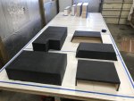
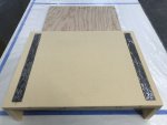
 

rruff

Explorer
No worries at all about a flat roof. When you're parked you'll be on an angle anyway. Ya, lots of sealant... The only thing I'm planning to have that penetrates the top is a vent-fan.

If you'd like curved roof pieces, you can build an interior frame with wood... just a few places along the length. Cut the top piece of foam, make sure it fits properly, then fiberglass the interior surface, and screw it to the frame. Then do the same the with corner/side pieces, fill in and sand the gaps, then fiberglass the exterior. Easy to conceive, but a PITA to do...

The curves look cooler for sure, but with the monstrosity ? you're building I doubt you'll notice the difference in driving or mpg.
 

Vance Vanz

Well-known member
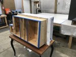
CF Floor Boxes & Wheel Well Layups - #1

I can’t believe it has been almost three weeks since my last post related to progress on the build. Where does the time go?

Whooh; I have been working my tail off these past two and a half weeks on the floor boxes. I know everything takes longer than expected, but with regard to CF/glassing, it is a whole other level!

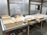
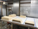
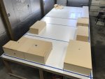
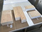
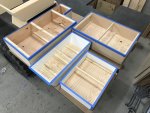
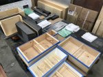
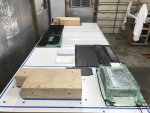
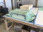
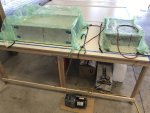
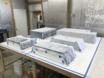
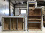
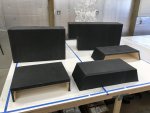
I decide to build all of the boxes/wheel wells for the floor together, as a batch instead of one at a time, in an attempt to save on set up and layup time-economies of scale. I had a total of five layups, three floor boxes (H20, battery and step) and two wheel wells.

The good news is, the CF for the outside of the floor boxes and wheels wells is complete?. The not so good news is, I have to basically do the entire process over again for the inside/opposite side of the boxes/wheel wells:oops:?.

So lets get to the progress, process and pictures:

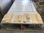
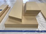
Cutting Foam (Gotta love the angles):
IMG_7513.jpegIMG_7514.jpeg

Bonding Foam:
IMG_7534.jpegIMG_7535.jpegIMG_7538.jpeg

Building Forms (For layup #1 of the boxes/wheel wells)
IMG_7540.jpegIMG_7541.jpegIMG_7549.jpeg

Cutting CF:
IMG_7548.jpegIMG_7554.jpeg

Continued......
 

Vance Vanz

Well-known member
CF Floor Boxes & Wheel Well Layups - #1 (Continued......)

Cutting Consumables:
IMG_7560.jpegIMG_7563.jpeg

Everything Ready for All Layups:
IMG_7564.jpeg

Set Up for H20 Box Layup:
IMG_7580.jpeg

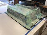
Vacuum Bagging:
IMG_7573.jpegIMG_7572.jpegIMG_7576.jpegIMG_7583.jpeg

Cured to Solid State:
IMG_7597.jpeg

Continued......
 

Vance Vanz

Well-known member
CF Floor Boxes & Wheel Well Layups - #1 (Continued......)

Are these things going to come off the forms :oops:??
IMG_7601.jpeg

Oh Yah Baby! (slowly but surely)
IMG_7603.jpegIMG_7604.jpeg

Peel Ply Party:
IMG_7600.jpegIMG_7602.jpegIMG_7605.jpeg

CF Revealed:
IMG_7607.jpegIMG_7610.jpeg

It's hard to imagine that this is weeks worth of work! There is so much more work and nuances to the process than the pictures can reflect.

Continued......
 
Last edited:

Vance Vanz

Well-known member
CF Floor Boxes & Wheel Well Layups - #1 (Continued......)

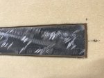
I thought I would also show some detailed pics of my step box, how I inlaid the steel into the layup. (Since there were some previous questions on this). This is similar to how the steel was inlaid in my floor.
IMG_7542.jpegIMG_7543.jpegIMG_7544.jpegIMG_7537.jpeg

The foam is cut 1/32-1/16" larger on the sides of the steel and about an 1/8" larger at the ends of the steel, to give some additional bonding space for the epoxy: The steel used here is 1/4" thick x 1.5" wide. Same principle as the floor, the steel is directly against the marine grade plywood as I did not want it against the CF. The steel acts as a large nut and also distributes the weight across the plywood and plywood across the entire surface area of the CF on the bottom of the step box. The steel will be drilled and tapped from the bottom side and four 3/8" grade 8 bolts will be used to mount the electric steps.

I will also have two additional steel L brackets mounted between the bottom side of the step box and the electric step mounting plate. These will help extend/distribute the weight/torque of the steps (when they open/are extended fully open) across the entire depth of the step box. A thin layer of rubber, HDPE, or UHMW will sit in between the steel L bracket and the CF on the bottom side of the step box-to protect the CF.
 
Last edited:

Forum statistics

Threads
187,298
Messages
2,893,113
Members
228,100
Latest member
havanother
Top