You are using an out of date browser. It may not display this or other websites correctly.
You should upgrade or use an alternative browser.
You should upgrade or use an alternative browser.
2022 Ford F550 - DIY - Adventure Expedition Vehicle Build Thread
- Thread starter Vance Vanz
- Start date
Vance Vanz
Well-known member
Thanks 38snubbyThis jankie website. It stopped sending me update to this thread. Amazing progress, my dude.
We're all in the club of NOT receiving updates on the threads we subscribe to. A lot of the time, I don't even receive updates for my own build thread
Just check in about every two weeks; it's about the max frequency I can post with the amount of hours I'm putting in on this beast
Vance Vanz
Well-known member
Thanks trackhead!This is simply amazing
I'm still swinging for the fences
We'll just see if I'm still standing when this thing is finally done
Vance Vanz
Well-known member
Auxiliary Fuel Tank & Factory Carbon Canister - Continued......
Someone inspired me to post a little sooner than I normally would.
Finally landed on a good spot for the canister
 !!
!!
A little welding here
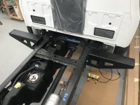
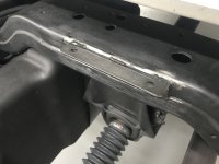
Some fabrication there
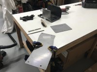
And a whole lotta dry fitting everywhere
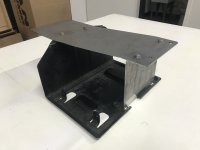
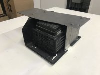
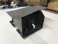
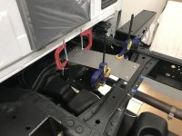
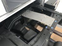
Well....., let's not forget about the onboard air! We might as well get that sorted while we're playing and making: brackets, brackets and more


 brackets.............
 !
!
Someone inspired me to post a little sooner than I normally would.
Finally landed on a good spot for the canister
A little welding here


Some fabrication there

And a whole lotta dry fitting everywhere


Well....., let's not forget about the onboard air! We might as well get that sorted while we're playing and making: brackets, brackets and more
Last edited:
Vance Vanz
Well-known member
ARB Onboard Air System
Let's get it all out and sorted.
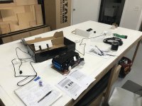
Another part/aftermarket system that I have to ditch all of the factory provided electrical wiring and connectors, because they are sized too small. Don't you love paying lot's of money for components on expensive systems that you can't use and/or have to throw away


 ?
?
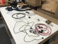
Back to those da( )mn brackets.

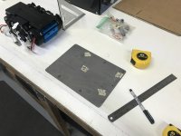
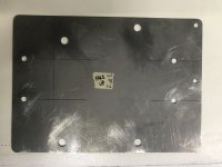
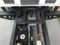
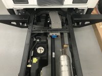
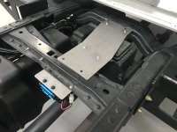
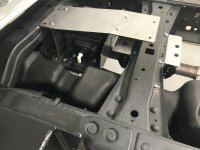
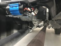
Let's get it all out and sorted.

Another part/aftermarket system that I have to ditch all of the factory provided electrical wiring and connectors, because they are sized too small. Don't you love paying lot's of money for components on expensive systems that you can't use and/or have to throw away

Back to those da(


I drilled some additional holes for mounting routing electrical wires and airlines as well. Don't want that to be an afterthought 
 !
!
With limited space under one of the last available factory-chassis-cross members at the back of the truck (highest cross members on the truck-to stay above the water line), real-estate was tight. I wanted to get the canister and the ARB compressor mounted at/on this single cross member (behind the cab). All other available locations to mount both of these items, put these two items at least 8-10"s lower in height.


The placement of the canister/compressor (at/by the gully in the top of the tank) allows for a perfect path for the vent lines on the canister, and the electrical wires/air lines on the compressor, to be routed over/through the gas tank and to/along the chassis rail. Also, the air inlets for the ARB compressor (that you can see in the above pic) will also get 90's and short nipples to increase the height of the inlets. This will put them just above the top of the chassis frame (37.5-38"). My water line is 34", a 1/2" or so below the bottom of the doors, so I'm trying to keep everything at 37-38" minimum off the ground. These are all of the layout and fitment details that take so much time to consider and figure out, but make the install so much smoother  !
!

There is plenty of clearance from the exhaust and driveline and the canister/compressor are also easily accessible for service if needed. Although the compressor could be installed in a more water tight location (like under the hood. I tried, no room), the whole front side of it is protected by the bracket for the canister. It's also tucked up tight enough (under the camper and between the chassis rails) that it should, hopefully, be fine from the elements.
Last edited:
Vance Vanz
Well-known member
Heating & Free Heat System - Rixen
Let's just keep rolling on BRACKETS!!!!
For all of these systems that I'm currently going through, it's not just the mounting/brackets that I'm figuring out. I'm going through the entire system, any and all elements of the system that I have not already sorted/finalized. This includes where and how it will be mounted, fabrication, material/hardware, electrical (sizing/wire/fusing/terminals/loom), fuel/vent/air/water/etc.-lines, fittings, sealers..............., etc. You get the idea! I'm finalizing and sourcing EVERYTHING, so I am basically 100% ready for the install (when it comes time for the install).
This is what I have been doing while the rig/camper have been at the LINE-X shop and the interior paint shop. As soon as I come up for air, after getting one system complete, I dive right into the next one. It's a bit BONKERS how long the design and layout, alone, can take, not to mention the time finding, pricing and sourcing all of the parts. After all of this, there are also several (hopefully not many) rounds of dry fitting and re-adjusting (if needed).
And the reward for all of this hard work and seeing everything dry fit (2-3times)...........?, take it all apart, put it back in the boxes and wait for the final install

 ...............
  . Prototype builds are MADNESS............., especially when you are basically doing it alone
  . Oooh Man; I'm pissing myself right now
  , about how much time all of this takes and how absurd it can feel at times!!!!
"Just keep moving forward"
 .
.
Rixen System (Outside of camper components):
Pulling everything out

This is where the outside components will be mounted
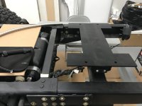
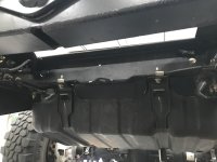
Espar, plate exchanger & fuel pump
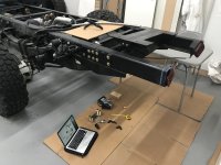
A little DIY CAD
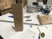
Snap your fingers three times............... and it magically appears!
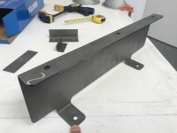
Did I mention about the process of dry fitting yet ? (#1)
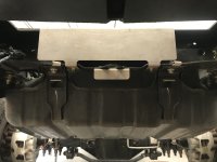
(#2 &3)

(#4)
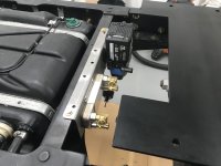
Let's just keep rolling on BRACKETS!!!!
For all of these systems that I'm currently going through, it's not just the mounting/brackets that I'm figuring out. I'm going through the entire system, any and all elements of the system that I have not already sorted/finalized. This includes where and how it will be mounted, fabrication, material/hardware, electrical (sizing/wire/fusing/terminals/loom), fuel/vent/air/water/etc.-lines, fittings, sealers..............., etc. You get the idea! I'm finalizing and sourcing EVERYTHING, so I am basically 100% ready for the install (when it comes time for the install).
This is what I have been doing while the rig/camper have been at the LINE-X shop and the interior paint shop. As soon as I come up for air, after getting one system complete, I dive right into the next one. It's a bit BONKERS
And the reward for all of this hard work and seeing everything dry fit (2-3times)...........?, take it all apart, put it back in the boxes and wait for the final install
"Just keep moving forward"
Rixen System (Outside of camper components):
Pulling everything out

This is where the outside components will be mounted


Espar, plate exchanger & fuel pump

A little DIY CAD

Snap your fingers three times............... and it magically appears!

Did I mention about the process of dry fitting yet

(#2 &3)

(#4)

Vance Vanz
Well-known member
Heating & Free Heat System - Rixen - Continued......
Getting the electrical, air intake and exhaust routed and dialed in, as well as drilling all of the holes in the chassis for mounting any/all lines (#6)
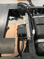
It's hard to see in the pic, because of the lighting, but I was stoked to be able to tuck the end of the air intake behind the bracket, which basically creates a little protective tube around the intake. This will help cut down on the dust/dirt/debris/elements reaching the inlet.
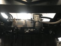
It was late, so I called it a night, but I had a little whisper that I couldn't put my finger on. The next morning I woke up and said "That fuel pump is not in the best spot! Although......, it is: in a good spot for serviceability, tucked up high enough, technically protected and the chances of something catching it are veeery slim! BUUUUUUUUUUT, there is still a chance that a branch and/or stout bush could catch the pump/fuel line, given the right 4x4 angle on the truck when the stars and moon align once every millennium!"
Sooooooo, it was decided (begrudgingly ), to move the da(
 )mn fuel pump
  .
.
Roundy-round , Roundy-round
  , Roundy-round
  and
and 
 ! "Mount it right next to all of the other fuel pumps, where you will be able to still access/service it when the camper is on." "Yes it will fit; just try harder and make it fit! Don't be lazy; this is not that kind of build!"
Factory fuel pump, Aux. fuel tank pump and Espar Rixen fuel pump. My little fuel pump farm.
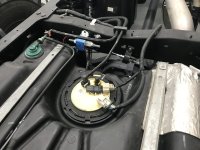
Still serviceable from the ground/bottom side when the camper is on.
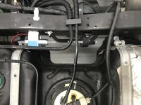
I can also route the fuel line with the existing factory fuel lines (Bonus).
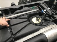
It may take me awhile, but I'll get there eventually!
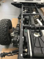
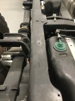
I also laid out and drilled several mounting holes down the chassis rail for mounting fuel fill/vent lines, as well as the coolant lines for the Rixen system (before the camper gets permanently set). I'm still not sure If I will be running the lines on the chassis rail, or the bottom of the camper. There are pros and cons for both, so I need to chew on it a little more. The holes also got some primer and paint (not shown).
One last piece of info that may be helpful to someone before we move away from the Rixen system (any system using the vehicles coolant/radiator for free heating). I was chatting with the neighboring build shop, when they were doing work on the ER (and it's heating/free-heat system). We started chatting about Pros and Cons of where to place the free-heat plate exchanger (Plate exchanger connected to the vehicles radiator/coolant loop).
One school of thought is to keep the vehicle to free-heat plate exchanger loop as short as possible. Meaning, mounting the free-heat plate exchanger as close to the vehicle's factory loop as possible (Basically, under the hood/at the engine). This minimizes the effect on the factory loop as much as possible and reduces the length of the coolant lines and number of fittings that could be susceptible to leaks. These are all Pros for a shorter factory vehicle loop (vehicle to free-heat plate exchanger).
A Con of this set-up is when you are not using free heating (coolant from the vehicle), and are using the Rixen Espar heater (in my build case) for heating (using fuel from your vehicle’s gas tank to supply/feed the Rixen Espar heater). With the free-heat plate exchanger being at the front of the vehicle (smaller free-heat loop), the heating loop is now longer. You now have to heat a longer loop when using fuel from your vehicle. Maybe not a big deal during the summer months, but if stationary during the dead of winter, you are now heating longer exposed lines (to the front of the vehicle).
The second school of thought is to put the free-heat plate exchanger at the back of the vehicle, or as close to the heater as possible (Rixen Espar heater for my build). The Pro of this setup is the heating loop is as short as possible and you heat a shorter loop when stationary (save on fuel). The Con is you have longer coolant lines and possibly more fittings in your vehicles factory loop, which could result in a leak and affect the vehicles factory coolant system (No coolant in your vehicle means no Drivey, Drivey and No Overlandy, Overlandy )
)
I know this is all a bit wordy and unfortunately, NO, a diagram will not be included. Unless, someone else is feeling spunky !
!
Yes, we could add more plate exchangers and pumps to the mix and start talking about multiple options and scenarios, but I'm keeping this related to just the use of free-heat from the vehicle.
I appreciated the conversation with my neighbors and it got me thinking about the question we often ask, "What is the BEST method?" Of course, the answer is often/always "It depends!" It also got me thinking about how we may do things without fully knowing why we are doing it the way we are doing it. After explaining what I was doing on my build, I had the ability/courage to ask them if they would do it differently, if they were building my build. Their answer was yes and I appreciated it.
My neighbors like the shorter free-heat loop to minimize the chances that the vehicle's factory loop could experience an issue. They were also mostly basing this off of seeing many shi(@&@&)tty installs. I agree with their points, but I prefer a longer free heat loop and a shorter heating loop.
Personally, If I'm going to tap into the factory system for free heating, I'm going to maximize the amount of free heating I can get. I'm also meticulous when it comes to building something, so I'm not worried about a sloppy install (The type of install where an unprotected/improperly routed coolant line would be rubbing on the factory chassis, or some other object it should not be rubbing on). In addition, mounting my plate exchanger at the back of the vehicle resulted in the same number of fittings I would have had to use if I mounted it close-ish to the engine.
This is all just food for thought and I wanted to take the time to mention it, since it happened during my dry-fitting-fun of the Rixen system. There is also one other addition I made/will install in my free-heat loop based upon previous experience of running this system in other builds, but no time to cover it now.
Enough Build-Threading for today. It is time for some Din Din and then back to designing the rear bumper/winch mount/spare tire carrier Combo and the rear roof ladder

 !
!

Getting the electrical, air intake and exhaust routed and dialed in, as well as drilling all of the holes in the chassis for mounting any/all lines (#6)

It's hard to see in the pic, because of the lighting, but I was stoked to be able to tuck the end of the air intake behind the bracket, which basically creates a little protective tube around the intake. This will help cut down on the dust/dirt/debris/elements reaching the inlet.

It was late, so I called it a night, but I had a little whisper that I couldn't put my finger on. The next morning I woke up and said "That fuel pump is not in the best spot! Although......, it is: in a good spot for serviceability, tucked up high enough, technically protected and the chances of something catching it are veeery slim! BUUUUUUUUUUT, there is still a chance that a branch and/or stout bush could catch the pump/fuel line, given the right 4x4 angle on the truck when the stars and moon align once every millennium!"
Sooooooo, it was decided (begrudgingly
Roundy-round
Factory fuel pump, Aux. fuel tank pump and Espar Rixen fuel pump. My little fuel pump farm.

Still serviceable from the ground/bottom side when the camper is on.

I can also route the fuel line with the existing factory fuel lines (Bonus).

It may take me awhile, but I'll get there eventually!
I also laid out and drilled several mounting holes down the chassis rail for mounting fuel fill/vent lines, as well as the coolant lines for the Rixen system (before the camper gets permanently set). I'm still not sure If I will be running the lines on the chassis rail, or the bottom of the camper. There are pros and cons for both, so I need to chew on it a little more. The holes also got some primer and paint (not shown).


One last piece of info that may be helpful to someone before we move away from the Rixen system (any system using the vehicles coolant/radiator for free heating). I was chatting with the neighboring build shop, when they were doing work on the ER (and it's heating/free-heat system). We started chatting about Pros and Cons of where to place the free-heat plate exchanger (Plate exchanger connected to the vehicles radiator/coolant loop).
One school of thought is to keep the vehicle to free-heat plate exchanger loop as short as possible. Meaning, mounting the free-heat plate exchanger as close to the vehicle's factory loop as possible (Basically, under the hood/at the engine). This minimizes the effect on the factory loop as much as possible and reduces the length of the coolant lines and number of fittings that could be susceptible to leaks. These are all Pros for a shorter factory vehicle loop (vehicle to free-heat plate exchanger).
A Con of this set-up is when you are not using free heating (coolant from the vehicle), and are using the Rixen Espar heater (in my build case) for heating (using fuel from your vehicle’s gas tank to supply/feed the Rixen Espar heater). With the free-heat plate exchanger being at the front of the vehicle (smaller free-heat loop), the heating loop is now longer. You now have to heat a longer loop when using fuel from your vehicle. Maybe not a big deal during the summer months, but if stationary during the dead of winter, you are now heating longer exposed lines (to the front of the vehicle).
The second school of thought is to put the free-heat plate exchanger at the back of the vehicle, or as close to the heater as possible (Rixen Espar heater for my build). The Pro of this setup is the heating loop is as short as possible and you heat a shorter loop when stationary (save on fuel). The Con is you have longer coolant lines and possibly more fittings in your vehicles factory loop, which could result in a leak and affect the vehicles factory coolant system (No coolant in your vehicle means no Drivey, Drivey and No Overlandy, Overlandy
I know this is all a bit wordy and unfortunately, NO, a diagram will not be included. Unless, someone else is feeling spunky
Yes, we could add more plate exchangers and pumps to the mix and start talking about multiple options and scenarios, but I'm keeping this related to just the use of free-heat from the vehicle.
I appreciated the conversation with my neighbors and it got me thinking about the question we often ask, "What is the BEST method?" Of course, the answer is often/always "It depends!" It also got me thinking about how we may do things without fully knowing why we are doing it the way we are doing it. After explaining what I was doing on my build, I had the ability/courage to ask them if they would do it differently, if they were building my build. Their answer was yes and I appreciated it.
My neighbors like the shorter free-heat loop to minimize the chances that the vehicle's factory loop could experience an issue. They were also mostly basing this off of seeing many shi(@&@&)tty installs. I agree with their points, but I prefer a longer free heat loop and a shorter heating loop.
Personally, If I'm going to tap into the factory system for free heating, I'm going to maximize the amount of free heating I can get. I'm also meticulous when it comes to building something, so I'm not worried about a sloppy install (The type of install where an unprotected/improperly routed coolant line would be rubbing on the factory chassis, or some other object it should not be rubbing on). In addition, mounting my plate exchanger at the back of the vehicle resulted in the same number of fittings I would have had to use if I mounted it close-ish to the engine.
This is all just food for thought and I wanted to take the time to mention it, since it happened during my dry-fitting-fun of the Rixen system. There is also one other addition I made/will install in my free-heat loop based upon previous experience of running this system in other builds, but no time to cover it now.
Enough Build-Threading for today. It is time for some Din Din and then back to designing the rear bumper/winch mount/spare tire carrier Combo and the rear roof ladder
Last edited:
Vance Vanz
Well-known member
Getting Back in the Saddle
Time Flies!
I guess I should get some content posted.
I’m going to start jumping all over the place, because that’s how the build has been going .
.
Rear View Mirror Split Camera:
Testing everything out.
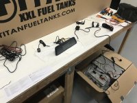
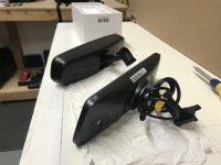
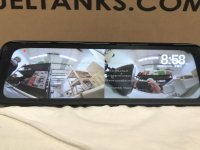
I wanted to run a camera on the front of the truck (grille/bumper area-centered), as well as a rear camera on the back of the camper (as high as possible-centered). The system will have small clean modern matching waterproof cameras. These two cameras will be run off of the aftermarket rearview mirror camera. You can toggle between one screen (front or back camera only), or a split screen for both cameras. It will be nice to see behind the camper (from a high vantage point) for normal/highway driving and also the front lower portion of the truck (ground that can’t be seen over the top of the hood) when wheeling.
You think this would be easy to find considering the number of MFG’s with rearview mirror cams out there, but I could only find one company that had a system that would work (matching waterproof externally mounted cameras that could be tied into a rearview mirror camera, not a dash mounted cam). Unfortunately, it took a lot of digging, many calls/emails and required me to do some additional firmware changes once I received everything.
I will also use a third matching waterproof externally mounted camera on the rear bumper (centered) and it will be tied into the factory dash mounted screen. Another aftermarket journey for all the needed items, as I did not want to use the bulky Ford factory cab chassis backup camera.
I’ll take pics when everything gets installed.
For now, it is: get it in the shop, test it to see if it will work, dry fit it 10 times (hopefully only 10 times), order all the remaining items that you need now that you know the part/parts you just ordered will work, do some more rounds of dry fitting now that just about everything has arrived and finally.................., put it all on the shelf to install it at a later date (a muuuuuuuuuuch later date). What a Fun Game they call building a prototype expedition vehicle.
Sleep Number Mattress:
I will be running a queen size Sleep Number Mattress in the Rig, so Erin and I can have our own cozy sides of the bed. When I initially did all of my research, I based it off of the combo air pump/control unit I saw in the store for the model/mattress I was interested in, as well as the type of fittings that came on the hoses (I needed 90’s on one side of the hoses as my mattress will sit directly on the composite-no bed platform).
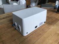

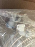

Well, low and behold, they change the pump/control module and hoses depending on what mattress you choose, whether it is comes on a base platform, ……… etc. I can’t tell you how many hours I spent on the phone trying to get the control unit I saw in the store, as well as the associated hoses with 90’s on one end. What they shipped was different. For me, it mattered, because I designed my bed area specifically for the pump/control unit that had the hoses coming out the end of the unit, as opposed to the side of it. The side hose unit is also a different shape and larger (and wouldn’t work for me). If anyone goes the Sleep Number (SN) route and has limited space, know there are two different style pumps.
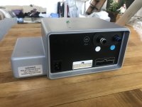
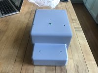
I also share all of this because SN has a mandatory $250 shipping fee, even for just a glorified air mattress (and no you can't go pick it up from the store either). They do have a satisfaction guarantee (full refund, no questions asked), but what they don’t tell you is it does not apply to the $250 non-negotiable shipping fee. Hence, why I just didn’t return everything and had to spend hours (maybe 5-6) trying to find someone that knew anything about their products.
Just trying to save anyone who is going the SN route some potential future pain
 .
.
Time Flies!
I guess I should get some content posted.
I’m going to start jumping all over the place, because that’s how the build has been going
Rear View Mirror Split Camera:
Testing everything out.


I wanted to run a camera on the front of the truck (grille/bumper area-centered), as well as a rear camera on the back of the camper (as high as possible-centered). The system will have small clean modern matching waterproof cameras. These two cameras will be run off of the aftermarket rearview mirror camera. You can toggle between one screen (front or back camera only), or a split screen for both cameras. It will be nice to see behind the camper (from a high vantage point) for normal/highway driving and also the front lower portion of the truck (ground that can’t be seen over the top of the hood) when wheeling.
You think this would be easy to find considering the number of MFG’s with rearview mirror cams out there, but I could only find one company that had a system that would work (matching waterproof externally mounted cameras that could be tied into a rearview mirror camera, not a dash mounted cam). Unfortunately, it took a lot of digging, many calls/emails and required me to do some additional firmware changes once I received everything.
I will also use a third matching waterproof externally mounted camera on the rear bumper (centered) and it will be tied into the factory dash mounted screen. Another aftermarket journey for all the needed items, as I did not want to use the bulky Ford factory cab chassis backup camera.
I’ll take pics when everything gets installed.
For now, it is: get it in the shop, test it to see if it will work, dry fit it 10 times (hopefully only 10 times), order all the remaining items that you need now that you know the part/parts you just ordered will work, do some more rounds of dry fitting now that just about everything has arrived and finally.................., put it all on the shelf to install it at a later date (a muuuuuuuuuuch later date). What a Fun Game they call building a prototype expedition vehicle.
Sleep Number Mattress:
I will be running a queen size Sleep Number Mattress in the Rig, so Erin and I can have our own cozy sides of the bed. When I initially did all of my research, I based it off of the combo air pump/control unit I saw in the store for the model/mattress I was interested in, as well as the type of fittings that came on the hoses (I needed 90’s on one side of the hoses as my mattress will sit directly on the composite-no bed platform).


Well, low and behold, they change the pump/control module and hoses depending on what mattress you choose, whether it is comes on a base platform, ……… etc. I can’t tell you how many hours I spent on the phone trying to get the control unit I saw in the store, as well as the associated hoses with 90’s on one end. What they shipped was different. For me, it mattered, because I designed my bed area specifically for the pump/control unit that had the hoses coming out the end of the unit, as opposed to the side of it. The side hose unit is also a different shape and larger (and wouldn’t work for me). If anyone goes the Sleep Number (SN) route and has limited space, know there are two different style pumps.


I also share all of this because SN has a mandatory $250 shipping fee, even for just a glorified air mattress (and no you can't go pick it up from the store either). They do have a satisfaction guarantee (full refund, no questions asked), but what they don’t tell you is it does not apply to the $250 non-negotiable shipping fee. Hence, why I just didn’t return everything and had to spend hours (maybe 5-6) trying to find someone that knew anything about their products.
Just trying to save anyone who is going the SN route some potential future pain
Last edited:
Vance Vanz
Well-known member
Grey Water Tank & Winches
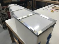
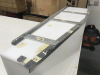
Fabricating the grey water tank frame.
I have a super tight space in the grey water tank compartment, so I had to get creative. My original idea would not work .
.
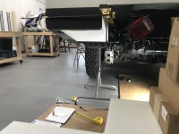
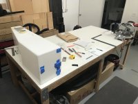
I ended up having to build a frame that had two separate brackets, with some additional bottom cross ties. One side of the frame will need to be installed (bolted to the camper), then the tank will be slid inside it and the other bracket will sandwich the other side of the tank. I also had to use Riv Nuts on one of the brackets, for the cross supports, because there was no room to get a hand/wrench/ratchet on a nut.
Winches:
I don't want to start the "fuse, or no fuse a winch?" debate, but here we go
 . I'm running fuses and isolation solenoids for both the front and rear winch (Warn 16.5Ti's) that will be wired into one of my upfitter switches .
Some info that may be helpful for those who want to run an isolation solenoid/contactor for a larger winch (upwards of 500A).
I wanted to go with a reputable marine grade solenoid/contactor for my very expensive winch. I looked into Blue Sea after checking out what appeared to be the only other available options (Amazon ones that may be hit or miss and who knows if they are actually rated for 500A/the stated ratings). The Blue Sea ones were pricey and I was having some trouble just taking my medicine. So, I started digging and making calls to the engineering departments as opposed to the sales departments.
Come to find out, Blue Sea just buys EGIS contactors and rebrands/labels them. Technically Blue Sea may have something built specific for them, but the option direct from EGIS had higher ampacity ratings and cost less. I was also able to find the EGIS option for the same price as the best rated Amazon option. Sold to the man who likes finding better products cheaper.
They are compact little suckers!

EGIS Contactor, 250 Amp, 12/24 V, Sealed (7021B)
https://www.egismobile.com/shop/7021b-contactor-250-amp-12-24-v-sealed-5449#attr=
NOTE: Although it comes up as a 250A solenoid/contactor (when doing online searches) it is a 400A continuous at 4/0AWG and 500A max for 5-10min. Since I'm running 4/0AWG and should never be cycling the winch on for longer than a few minutes at a time, I have a 500A rated solenoid/contactor for a reasonable price. A quick search will get you pricing lower than the associated link.
Fusing a winch. Since I come from a technical trade background (electrical being a large part of that background) electrical circuits get fuses/breakers/protection. It's that simple for me.
I've got plenty of room to mount the fuse holder for the rear winch, but under the hood for the front winch was a different story. The only place I could find that had some room, and made sense given my wire route and location of my solenoid/contactor, was on the battery bracket.
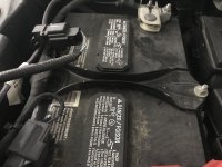
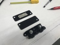
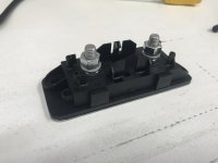
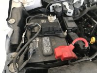
I'll weld the base plate to the battery bracket and get it off to powder coat at some point. On to the next project.
Fabricating the grey water tank frame.
I have a super tight space in the grey water tank compartment, so I had to get creative. My original idea would not work

I ended up having to build a frame that had two separate brackets, with some additional bottom cross ties. One side of the frame will need to be installed (bolted to the camper), then the tank will be slid inside it and the other bracket will sandwich the other side of the tank. I also had to use Riv Nuts on one of the brackets, for the cross supports, because there was no room to get a hand/wrench/ratchet on a nut.


Winches:
I don't want to start the "fuse, or no fuse a winch?" debate, but here we go
Some info that may be helpful for those who want to run an isolation solenoid/contactor for a larger winch (upwards of 500A).
I wanted to go with a reputable marine grade solenoid/contactor for my very expensive winch. I looked into Blue Sea after checking out what appeared to be the only other available options (Amazon ones that may be hit or miss and who knows if they are actually rated for 500A/the stated ratings). The Blue Sea ones were pricey and I was having some trouble just taking my medicine. So, I started digging and making calls to the engineering departments as opposed to the sales departments.
Come to find out, Blue Sea just buys EGIS contactors and rebrands/labels them. Technically Blue Sea may have something built specific for them, but the option direct from EGIS had higher ampacity ratings and cost less. I was also able to find the EGIS option for the same price as the best rated Amazon option. Sold to the man who likes finding better products cheaper.
They are compact little suckers!

EGIS Contactor, 250 Amp, 12/24 V, Sealed (7021B)
https://www.egismobile.com/shop/7021b-contactor-250-amp-12-24-v-sealed-5449#attr=
NOTE: Although it comes up as a 250A solenoid/contactor (when doing online searches) it is a 400A continuous at 4/0AWG and 500A max for 5-10min. Since I'm running 4/0AWG and should never be cycling the winch on for longer than a few minutes at a time, I have a 500A rated solenoid/contactor for a reasonable price. A quick search will get you pricing lower than the associated link.
Fusing a winch. Since I come from a technical trade background (electrical being a large part of that background) electrical circuits get fuses/breakers/protection. It's that simple for me.
I've got plenty of room to mount the fuse holder for the rear winch, but under the hood for the front winch was a different story. The only place I could find that had some room, and made sense given my wire route and location of my solenoid/contactor, was on the battery bracket.


I'll weld the base plate to the battery bracket and get it off to powder coat at some point. On to the next project.
Last edited:
Vance Vanz
Well-known member
Fuel & Water Fills (Housing & Doors)
Here is my initial attempt at getting the fuel fills sorted. Water fills are fine, but the fuel fills are no bueno .
.
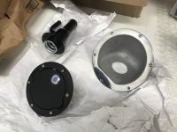
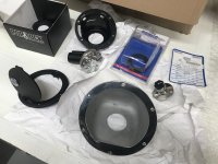
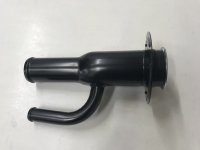
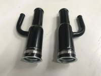
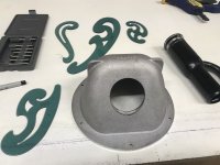
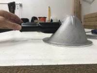
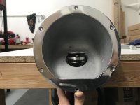
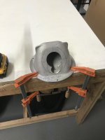
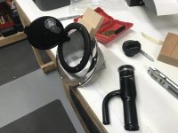
There were also several late night trips to a closed gas station to test all of this with an actual gas pump nozzle.
My fuel fills will be on the side of the camper, fuel lines ran inside of the camper, like ER. I have a very tight space (I think less than 5"s-it's been a while since I was on this project) to get the housing and filler neck to fit at a 90 degree orientation to the side wall of the camper. Long story short, I'm going to have to revisit this.
I think the answer will be to cut and re-weld the filler necks at the exact angle I need. I had other pressing projects, so this went back on the shelf. The crap I'm having to do to get this this build off the ground is insane .
.
NEXT!!!!
Here is my initial attempt at getting the fuel fills sorted. Water fills are fine, but the fuel fills are no bueno


There were also several late night trips to a closed gas station to test all of this with an actual gas pump nozzle.
My fuel fills will be on the side of the camper, fuel lines ran inside of the camper, like ER. I have a very tight space (I think less than 5"s-it's been a while since I was on this project) to get the housing and filler neck to fit at a 90 degree orientation to the side wall of the camper. Long story short, I'm going to have to revisit this.
I think the answer will be to cut and re-weld the filler necks at the exact angle I need. I had other pressing projects, so this went back on the shelf. The crap I'm having to do to get this this build off the ground is insane
NEXT!!!!
Vance Vanz
Well-known member
Heating Pads & Surfboard Rack
I told you we were going to jump around . Who would have thought heating pads and surfboard racks would be in the same post
  .
.
Grey Water Tank & Battery Heating Pads:
This baby will be 4 season, so I gotta keep things warm in the dead of winter.
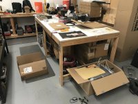
I try and test everything electrical when I receive it (within reason). The heaters have internal stats and I wanted to see if they actually worked anywhere near the range they state. I will also be installing separate inline temp sensors/cut outs to tighten up the temp swing.
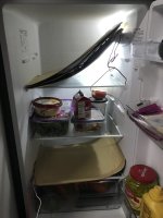
I eventually put them in the freezer as well.
Surfboard Rack:
This was the surfboard rack someone was nice enough to recommend in one of the initial responses to the build thread. Thanks again for that recommendation, if you are still out there. I finally pulled the trigger on it and sorry it just happened to be SEVERAL YEARS later. I'm a slow worker
 !
!
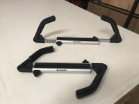
After a ton of research, this was the best lockable surfboard rack I could find that could be (for the most part) universally mounted. I also had to just buy it, in order to get all of the specific dims/specs on it to see if it would work.
The closest thing to an adventure I've had on the build. Some day, some day .
.
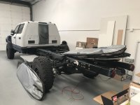
I needed to be able to store a long board and a fun board (stacked and in their bags) on the roof. My short board will go in the gear locker with the MTB's. They just fit .
.
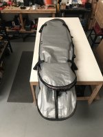
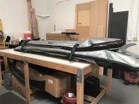
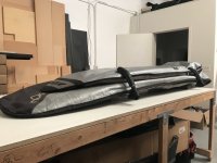
I also took all of the preliminary measurements to figure out how they will be attached to the roof and the exact spacing everything will need to be. It's going to be super tight on the roof. I was originally going to go with basic round cross bars, which would have been super simple, cheap and low profile, but the locking options (locking straps) were not as good of an option as these. I needed something more theft proof than straps that could be cut with a basic pair of wire cutters.
The only negative with these racks, compared to the cross bars, (in relation to where the boards will sit on the rack), is they are wider. The arms will place the surfboards further out into the walkway on the roof, which was already tight/small to begin with. I'll revisit some of this when I start designing the slide out solar arrays.
I told you we were going to jump around
Grey Water Tank & Battery Heating Pads:
This baby will be 4 season, so I gotta keep things warm in the dead of winter.
I try and test everything electrical when I receive it (within reason). The heaters have internal stats and I wanted to see if they actually worked anywhere near the range they state. I will also be installing separate inline temp sensors/cut outs to tighten up the temp swing.

I eventually put them in the freezer as well.

Surfboard Rack:
This was the surfboard rack someone was nice enough to recommend in one of the initial responses to the build thread. Thanks again for that recommendation, if you are still out there. I finally pulled the trigger on it and sorry it just happened to be SEVERAL YEARS later. I'm a slow worker

After a ton of research, this was the best lockable surfboard rack I could find that could be (for the most part) universally mounted. I also had to just buy it, in order to get all of the specific dims/specs on it to see if it would work.
The closest thing to an adventure I've had on the build. Some day, some day

I needed to be able to store a long board and a fun board (stacked and in their bags) on the roof. My short board will go in the gear locker with the MTB's. They just fit


I also took all of the preliminary measurements to figure out how they will be attached to the roof and the exact spacing everything will need to be. It's going to be super tight on the roof. I was originally going to go with basic round cross bars, which would have been super simple, cheap and low profile, but the locking options (locking straps) were not as good of an option as these. I needed something more theft proof than straps that could be cut with a basic pair of wire cutters.
The only negative with these racks, compared to the cross bars, (in relation to where the boards will sit on the rack), is they are wider. The arms will place the surfboards further out into the walkway on the roof, which was already tight/small to begin with. I'll revisit some of this when I start designing the slide out solar arrays.
Last edited:
Vance Vanz
Well-known member
Heat Shielding the Gas Tank
I didn't realize the time . My last post before I get my butt to bed
  . I have a long day of designing tomorrow. Hopefully my gramar and speling have'nt been atracious
  !
!
My little rant...........
I'm always surprised to see when builders (the professionals-I promise I won't name any names) extend/re-route the exhaust pipe on a build, the exhaust pipe ends up being far closer to the gas tank than any OEM section of pipe and they don't heat shield the tank (Especially, when the factory heat shielded a portion of the tank).
OK, rant done now.
Believe me, this is the last thing I wanted to do on the build. I have so many other projects that I need to complete that are more important. I could have just said screw it, and buried my head in the sand, but I'm unfortunately not wired that way. So here we go with the task I think I least want to do on the entire build (besides filling pits and sanding of course).
To all of those damn tasks you just DON'T WANT TO DO .
.
Get the gas out of the tank and try not to blow yourself up while doing it

A little safety net in case it doesn't want to play nice and stay on the floor jack for the duration of the ride.
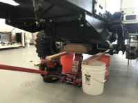
Not so bad. But, why do I hate simple tasks like dropping a gas tank just to install a small section of heat shield on it, SO MUCH?
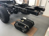
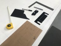
Should I just slap a large rectangle on the tank, press it down and call it good, or take the time to do a template.
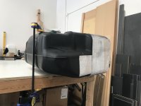
A template it is.
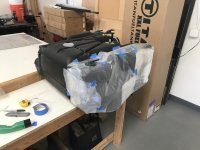
I'm going to make this fun and do the entire thing with one continuous piece.
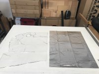
I also foil taped all of the seams (not shown) just to be extra sure everything stays
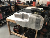
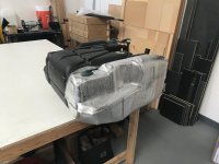
The details that you will never see, but you know are there
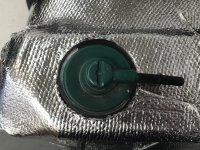
To the completion of the 3rd highest ranked thing on the build that I hated doing the most
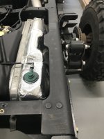
Who said this wasn't fun?
Until next time. Night, Night!
I didn't realize the time
My little rant...........
I'm always surprised to see when builders (the professionals-I promise I won't name any names) extend/re-route the exhaust pipe on a build, the exhaust pipe ends up being far closer to the gas tank than any OEM section of pipe and they don't heat shield the tank (Especially, when the factory heat shielded a portion of the tank).
OK, rant done now.
Believe me, this is the last thing I wanted to do on the build. I have so many other projects that I need to complete that are more important. I could have just said screw it, and buried my head in the sand, but I'm unfortunately not wired that way. So here we go with the task I think I least want to do on the entire build (besides filling pits and sanding of course).
To all of those damn tasks you just DON'T WANT TO DO
Get the gas out of the tank and try not to blow yourself up while doing it

A little safety net in case it doesn't want to play nice and stay on the floor jack for the duration of the ride.

Not so bad. But, why do I hate simple tasks like dropping a gas tank just to install a small section of heat shield on it, SO MUCH?

Should I just slap a large rectangle on the tank, press it down and call it good, or take the time to do a template.

A template it is.

I'm going to make this fun and do the entire thing with one continuous piece.

I also foil taped all of the seams (not shown) just to be extra sure everything stays


The details that you will never see, but you know are there

To the completion of the 3rd highest ranked thing on the build that I hated doing the most

Who said this wasn't fun?
Until next time. Night, Night!
Vance Vanz
Well-known member
Heating System & Auxiliary Alternator
Not the most exciting stuff, but all of the items that just consume a lot of time on the build.
I needed to finalize how I was going to route and support the ¾” x two coolant hoses from the engine compartment to the very back of the camper (for the Rixen System). Not too difficult running down the chassis frame, but in the engine compartment was a different story. I wanted the runs as short as possible and the lines out of the way as much as possible (so servicing anything/everything in the engine compartment didn’t become a problem as a result of the lines being in the way/needing to be drained and removed). The simplest and cleanest way (I decided), was across the top of the firewall. I will also be routing all of the electrical for the aftermarket items/upfitter switches along this same path.
Rather than try and hang everything off of the factory plastic, I decided to use some of the existing studs on the fire wall and add two more mounting points. Everything will be thoroughly supported/hard-ish mounted to the fire wall.
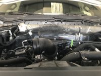
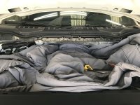
I had to pull up the factory plastic (below the windshield/above the firewall) to make sure the rivnuts would not interfere with the wipers. Plenty of room back there, but getting a rivnut tool to fit required some disassembly of the air intake fittings/lines.

Dry fitting the hoses across and squeezing in one last (soon to be fabricated) bracket so the lines avoid: all of the steering, exhaust, suspension and route cleanly toward the chassis frame and under the cab. (I know that this is a large nut, for a few threads on the steering housing, but this is a dry fit for templating purposes. I'll have more threads for the nut when everything gets installed
 ).
).
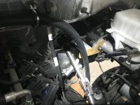
Getting the angle juuuuuust right on the bracket, and to fit/lock against the housing (anti-rotational lock) took a couple of tries.
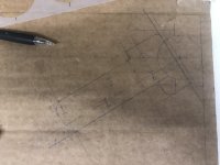
Here is the SS iso valve I will install in the engine to plate exchanger loop. I will wire it to one of my upfitter switches (NO valve). It will allow me to stop flow to/in the loop during the winter, when it is super cold. This way all of the factory engine loop heat stays in the factory loop when I energize the valve. After the truck has warmed up and it is toasty in the cab/windows defrosted, I can de-energize the valve and allow the Rixen/Free heat loop to flow.

Not a huge issue/deal, but in my campervan I hated getting in the truck after a cold day of skiing/mountaineering and it taking forever for the cab to get warm because all of my heat was getting lost in the loop all the way to the back of the van .
.
Part of the jumping around process on all of these various random projects included accounting for everything that will need to be mounted in, and/or ran through, the engine compartment and cab. I wanted to account for every aftermarket item and system that enters/exits the engine compartment and cab, so I could consolidate all of my lines and wiring. I want everything to route together and to do it in one shot. This is why there is a lot of random dryfitting and jumping around. The final install will be clean and cohesive. The dry fit everything and put it back on the shelf process is getting old though ...............
In addition to the process above, I'm also accounting for all of my electrical runs and needed terminals, so I can size all of my wire and make, hopefully, just ONE purchase. Saving some cash on ordering all of my wire and terminals, in one shot, is going to be needed as this beast of a build is getting beastly expensive.
Last shake down on the layout, mounting, routing and wiring before everything gets installed for the auxiliary alternator. Making sure I have EVERYTHING I need.
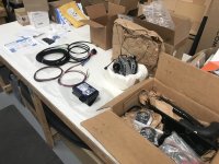
Not the most exciting stuff, but all of the items that just consume a lot of time on the build.
I needed to finalize how I was going to route and support the ¾” x two coolant hoses from the engine compartment to the very back of the camper (for the Rixen System). Not too difficult running down the chassis frame, but in the engine compartment was a different story. I wanted the runs as short as possible and the lines out of the way as much as possible (so servicing anything/everything in the engine compartment didn’t become a problem as a result of the lines being in the way/needing to be drained and removed). The simplest and cleanest way (I decided), was across the top of the firewall. I will also be routing all of the electrical for the aftermarket items/upfitter switches along this same path.
Rather than try and hang everything off of the factory plastic, I decided to use some of the existing studs on the fire wall and add two more mounting points. Everything will be thoroughly supported/hard-ish mounted to the fire wall.


I had to pull up the factory plastic (below the windshield/above the firewall) to make sure the rivnuts would not interfere with the wipers. Plenty of room back there, but getting a rivnut tool to fit required some disassembly of the air intake fittings/lines.

Dry fitting the hoses across and squeezing in one last (soon to be fabricated) bracket so the lines avoid: all of the steering, exhaust, suspension and route cleanly toward the chassis frame and under the cab. (I know that this is a large nut, for a few threads on the steering housing, but this is a dry fit for templating purposes. I'll have more threads for the nut when everything gets installed

Getting the angle juuuuuust right on the bracket, and to fit/lock against the housing (anti-rotational lock) took a couple of tries.

Here is the SS iso valve I will install in the engine to plate exchanger loop. I will wire it to one of my upfitter switches (NO valve). It will allow me to stop flow to/in the loop during the winter, when it is super cold. This way all of the factory engine loop heat stays in the factory loop when I energize the valve. After the truck has warmed up and it is toasty in the cab/windows defrosted, I can de-energize the valve and allow the Rixen/Free heat loop to flow.

Not a huge issue/deal, but in my campervan I hated getting in the truck after a cold day of skiing/mountaineering and it taking forever for the cab to get warm because all of my heat was getting lost in the loop all the way to the back of the van
Part of the jumping around process on all of these various random projects included accounting for everything that will need to be mounted in, and/or ran through, the engine compartment and cab. I wanted to account for every aftermarket item and system that enters/exits the engine compartment and cab, so I could consolidate all of my lines and wiring. I want everything to route together and to do it in one shot. This is why there is a lot of random dryfitting and jumping around. The final install will be clean and cohesive. The dry fit everything and put it back on the shelf process is getting old though
In addition to the process above, I'm also accounting for all of my electrical runs and needed terminals, so I can size all of my wire and make, hopefully, just ONE purchase. Saving some cash on ordering all of my wire and terminals, in one shot, is going to be needed as this beast of a build is getting beastly expensive.
Last shake down on the layout, mounting, routing and wiring before everything gets installed for the auxiliary alternator. Making sure I have EVERYTHING I need.

Last edited:
Vance Vanz
Well-known member
Slide Out Solar Panel Rack/Arrays
I was originally super excited about this project, in the beginning of the build

 . BUUUUT….., now that we are (I am) years deep into this project, I have been contemplating whether to scrap the stacking solar panel slide out racks altogether.
I had to go back to my question, “At the end of the build would you regret not doing it?" Ahhhhhhhhhh SH(

 )IT, this is going to take some time and energy I really don’t have right now. Head down, one foot in front of the other and I’ll eventually figure it out and make it to the finish line.
Here we go………
After many hours of sourcing SS slides, linear actuators and making sure everything is going to preliminarily fit-ish in the tight spaces I have on the roof, I got down to the hard math/the real design process.
Step 1 sorting out the layout of the SS slides and mounting feet
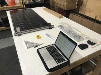
Step 2 where and how to mount the linear actuators
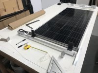
Originally, I was going to keep it simple and do a manual slide out rack, one I would manually lock/unlock and slide out from the roof. The reality of that design, designs I was coming up with, were not going to work. It would have been unsafe to try and lock, unlock and slide the racks given the tight space I have on the roof. Also, the arrays are pretty big, so it would have been a cumbersome process with one person, even if I was able to find a safe way to make it all happen.
So, I had to make it a bit more expensive and involved and go with electric linear actuators. No pneumatics for me, thank you very much, too much maintenance and noise.
Pulling things apart to get the body brackets on
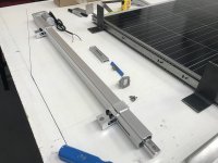
Playing with different ideas on how to mount the actuators
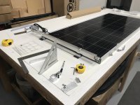
I will have two stacked solar panel array racks on each side of the roof. A two solar panel stacked array for the drivers side (D.S.) and a three panel stacked array for the passenger side (P.S.). The bottom racks will slide and the tops will be fixed. 10 panels total, at 215 watts a piece. Overkill? Maybe to some. For me, I don't ever want to have to stress about power/running the AC if we are parked at an off grid epic surf/adventure spot for 3-4 days at a time. Power and water won't be stressors for this build.
Since I have a few things to work around on the roof (A/C, vent fan, skylight, surfboard rack......), I had to get creative on orienting and mounting the actuators. All four of them could not be mounted in the same orientation. Not that big of a deal, but just more design time and head scratching.
Two of the actuators on opposing racks were close enough to the L track that will be used to mount the surfboard rack, so I just decided to mount everything on one piece of L track that will span the entire width of the roof. This simplified things in some ways, but also added to the design time/re-work time.
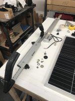
It's going to be tight, but it will just fit with about an inch to spare
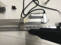
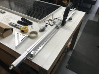
I haven't had to cross between/try and combine using L track and T slot before. At first, I wasn't sure how I was going to mount the surf board racks to L track in a simple/low profile way, considering the provided mounting hardware was designed for T slot. My brain just latched onto, I have to somehow make an L track stud work, or make some custom mount myself. It wasn't until I picked up the provided T slot hardware/mount, while thinking I may be able to grind it down in some way, that I actually tried to slide it in the L track from the side. What DAAAH you know, it slid right in . Silly me!
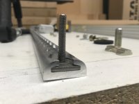
I can't tell you how stoked I was about that; it saved me hours of time not having to reinvent the wheel.
I was originally super excited about this project, in the beginning of the build
I had to go back to my question, “At the end of the build would you regret not doing it?" Ahhhhhhhhhh SH(
Here we go………
After many hours of sourcing SS slides, linear actuators and making sure everything is going to preliminarily fit-ish in the tight spaces I have on the roof, I got down to the hard math/the real design process.
Step 1 sorting out the layout of the SS slides and mounting feet

Step 2 where and how to mount the linear actuators

Originally, I was going to keep it simple and do a manual slide out rack, one I would manually lock/unlock and slide out from the roof. The reality of that design, designs I was coming up with, were not going to work. It would have been unsafe to try and lock, unlock and slide the racks given the tight space I have on the roof. Also, the arrays are pretty big, so it would have been a cumbersome process with one person, even if I was able to find a safe way to make it all happen.
So, I had to make it a bit more expensive and involved and go with electric linear actuators. No pneumatics for me, thank you very much, too much maintenance and noise.
Pulling things apart to get the body brackets on

Playing with different ideas on how to mount the actuators

I will have two stacked solar panel array racks on each side of the roof. A two solar panel stacked array for the drivers side (D.S.) and a three panel stacked array for the passenger side (P.S.). The bottom racks will slide and the tops will be fixed. 10 panels total, at 215 watts a piece. Overkill? Maybe to some. For me, I don't ever want to have to stress about power/running the AC if we are parked at an off grid epic surf/adventure spot for 3-4 days at a time. Power and water won't be stressors for this build.
Since I have a few things to work around on the roof (A/C, vent fan, skylight, surfboard rack......), I had to get creative on orienting and mounting the actuators. All four of them could not be mounted in the same orientation. Not that big of a deal, but just more design time and head scratching.
Two of the actuators on opposing racks were close enough to the L track that will be used to mount the surfboard rack, so I just decided to mount everything on one piece of L track that will span the entire width of the roof. This simplified things in some ways, but also added to the design time/re-work time.

It's going to be tight, but it will just fit with about an inch to spare


I haven't had to cross between/try and combine using L track and T slot before. At first, I wasn't sure how I was going to mount the surf board racks to L track in a simple/low profile way, considering the provided mounting hardware was designed for T slot. My brain just latched onto, I have to somehow make an L track stud work, or make some custom mount myself. It wasn't until I picked up the provided T slot hardware/mount, while thinking I may be able to grind it down in some way, that I actually tried to slide it in the L track from the side. What DAAAH you know, it slid right in

I can't tell you how stoked I was about that; it saved me hours of time not having to reinvent the wheel.
Last edited:
Similar threads
- Replies
- 5
- Views
- 418
- Replies
- 25
- Views
- 2K
- Replies
- 11
- Views
- 938
- Replies
- 2
- Views
- 543
- Replies
- 0
- Views
- 804
