hobietony
Explorer
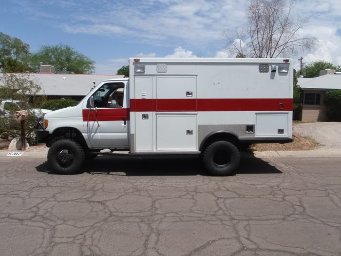
The rig is looking great! Seems like you like that DPTuner, I know I love mine and can't take it off that 80hp setting LOL, no way its going back to stock. About your a/c, the only thing I found that will cool that big ol' box in 100*+ temps is a roof top a/c or similar. I tried making the rear a/c work for weeks and it just can't keep up, even after basicly rebuilding the whole a/c and getting it to work perfectly, the front works great but the rear just doesnt have the capacity to handle all that space at those temps. I finally decided to copy the big rv's and installed the roof top 13,500but unit and let it run off generator cruising down the road just like the big rv's do. I installed an automatic switch so all we have to do is plug in shore power and it goes from generator to shore automaticly and charges my batteries driving down the road.
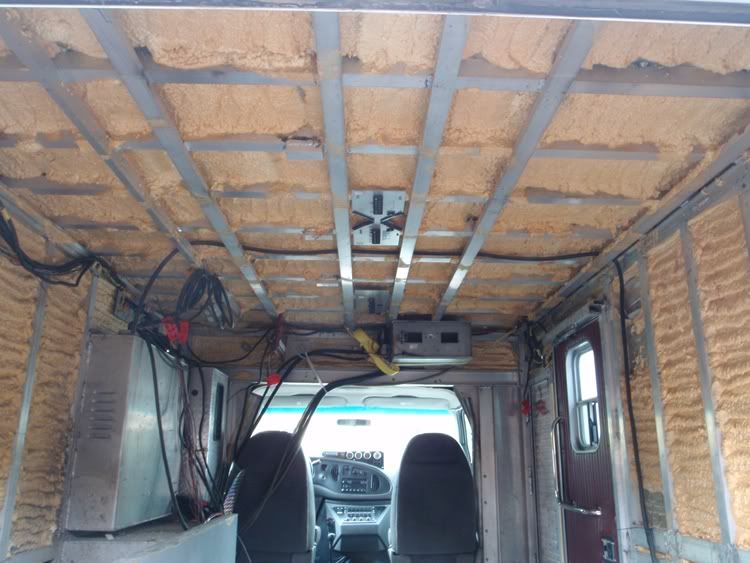
I figure I at least have to have the system functional before I get the AC charged, but yes, I agree that the big hammer solution is going to have the rooftop AC going. I put in 2 big 4d batteries, and a 2000 zantrex inverter, so I think that the AC will work off that while I am driving, without having to run a genny.
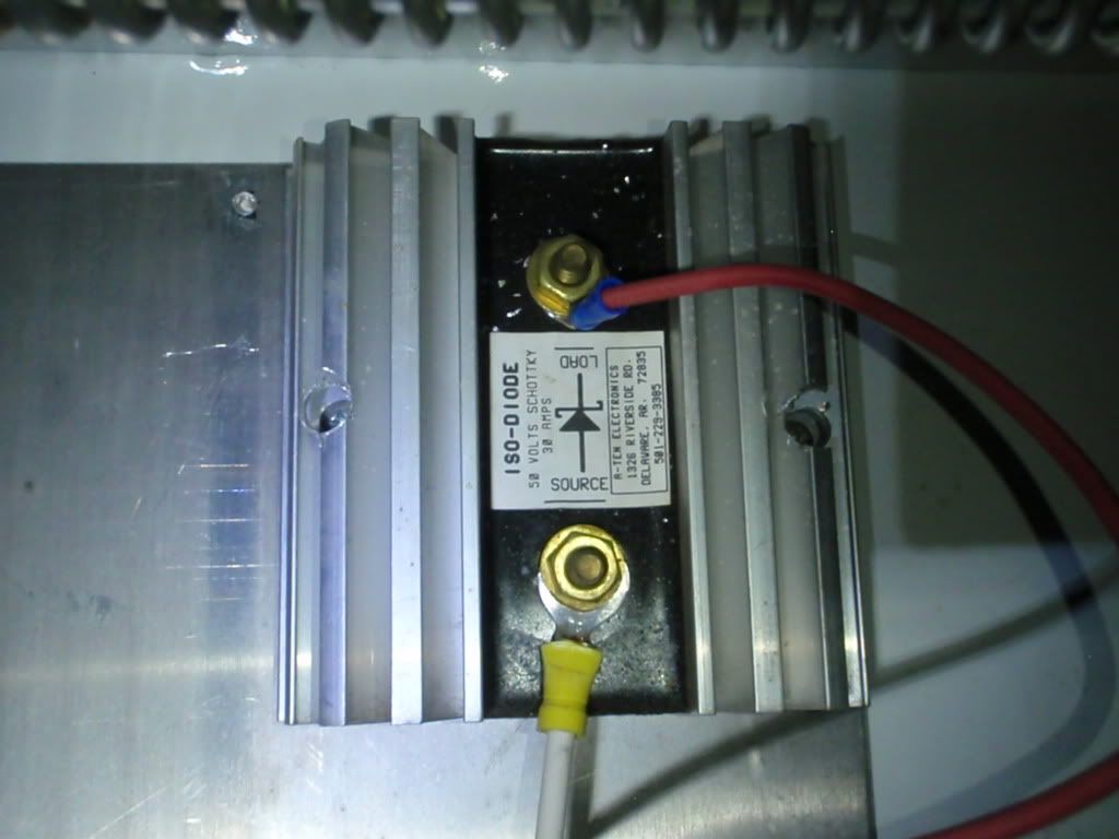
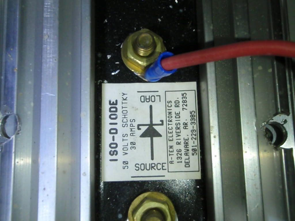
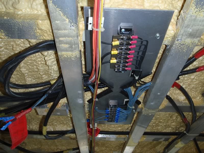
Otherwise, I havent heard any good reason to keep that diode hooked up, so out it goes.