Review: Auxbeam Bluetooth-enabled 8-Circuit Switch Panel
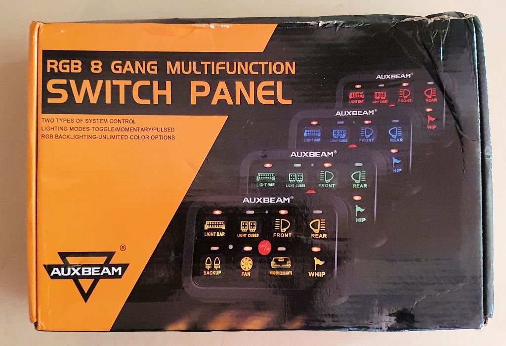
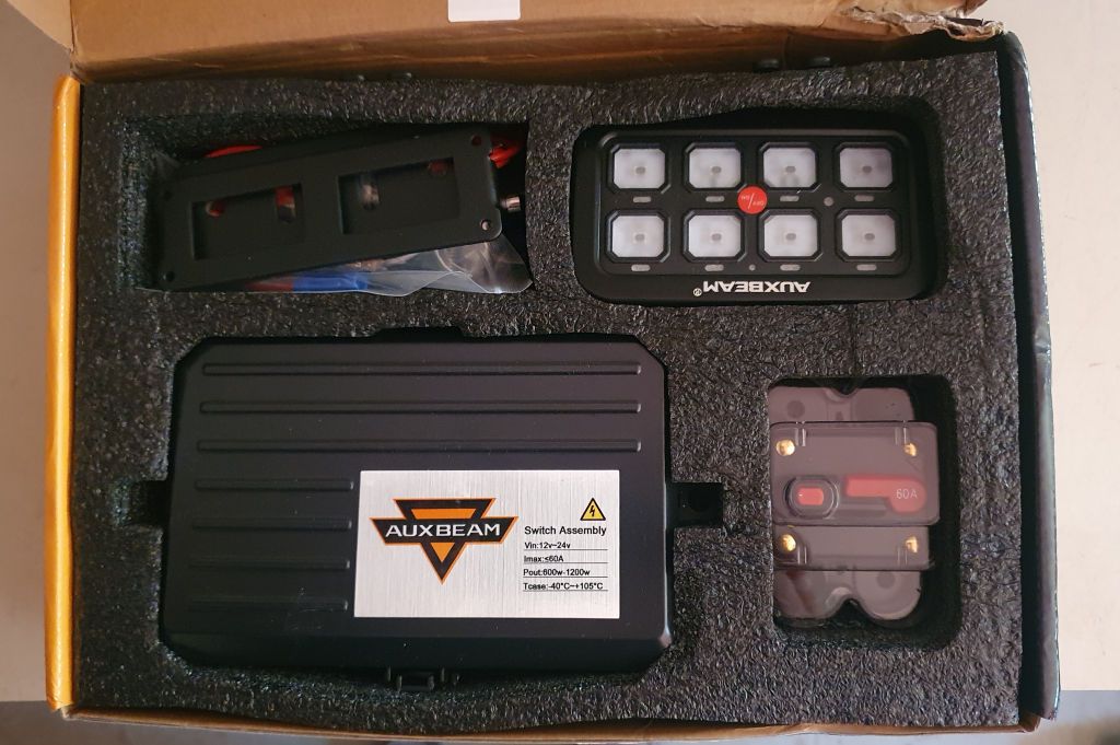
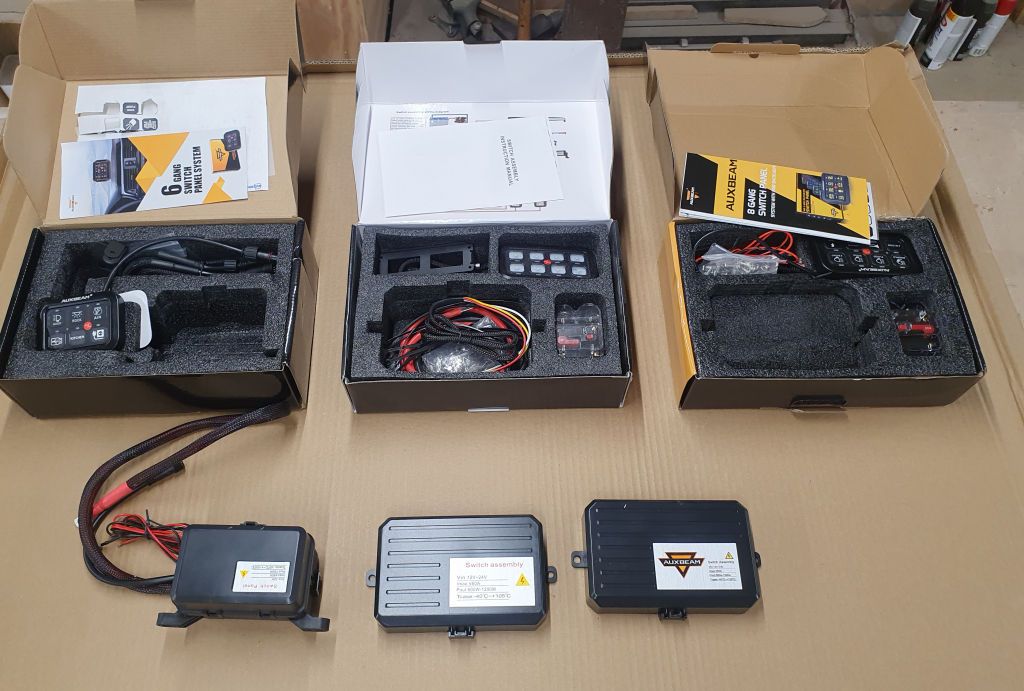
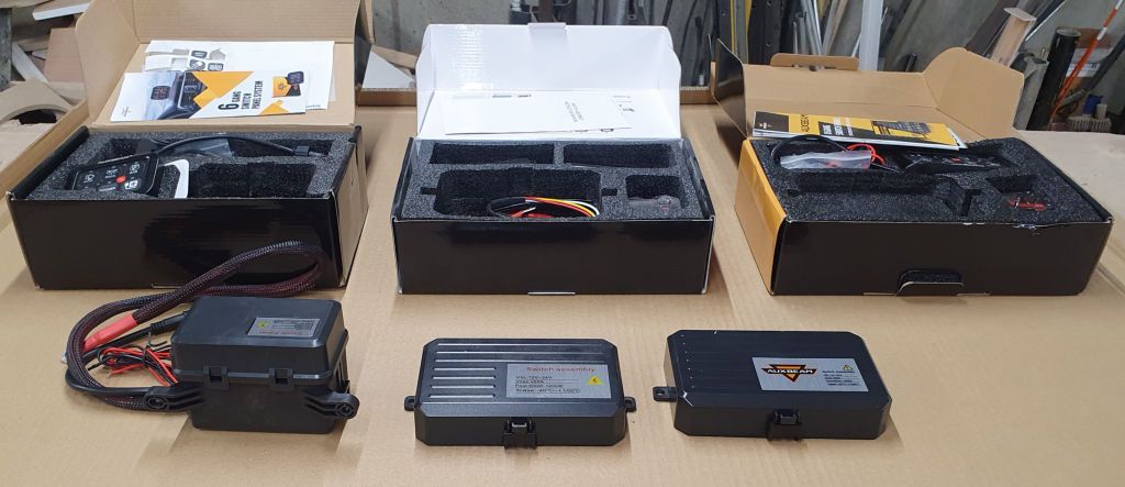
Auxbeam recently released a new Bluetooth-enabled switch panel. It's similar to other Auxbeam switch panels I've reviewed in the past, but this one can be controlled from a smartphone app via Bluetooth and also has configurable color settings for the switch backlights and configurable switch actions. They sent me one to test and review, it arrived the other day:
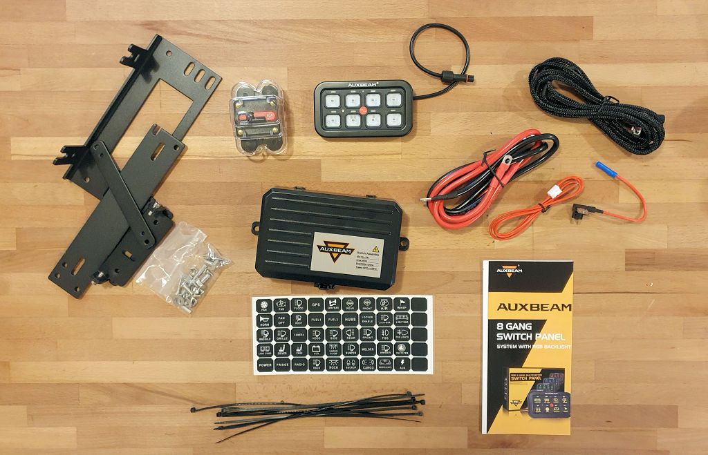
The contents of the kit:
The control unit is in the center of the photo above, and clockwise from top left there's a selection of mounting brackets for various locations, a 60-amp circuit breaker, the switch panel, various wiring components and hardware, instructions, switch faces and a bunch of zip ties.
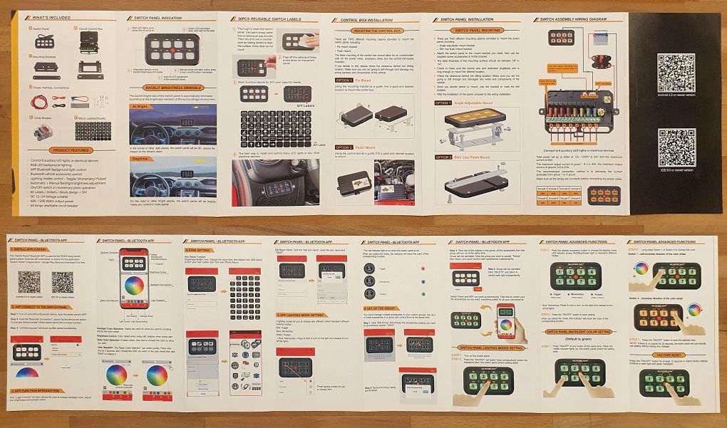
The instructions are thorough:
The QR Codes at the top right of the photo above are links to the app for both Android phones and iPhones. I downloaded, installed and tested both the Android and the iPhone versions.
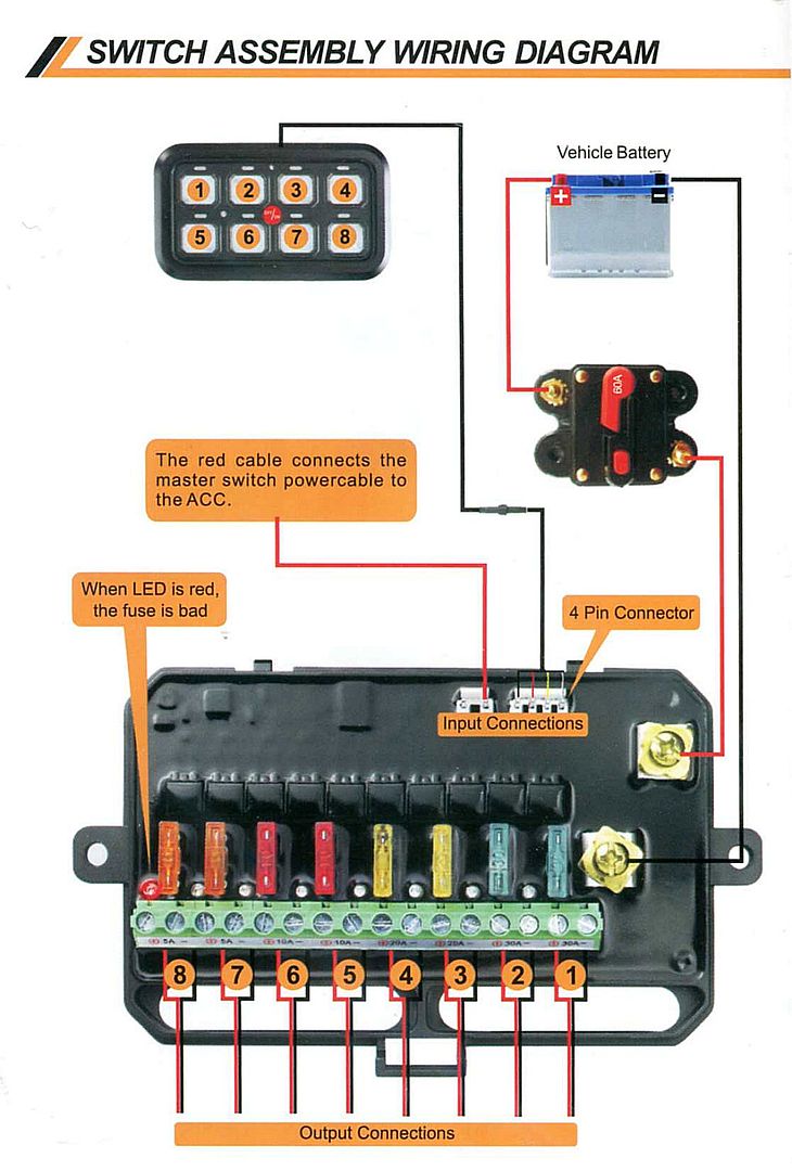
Wiring is straightforward, this is the wiring diagram from the instructions:
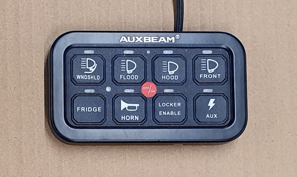
The kit comes with 60 removable switch labels; I put a random selection of them on the panel for this test.
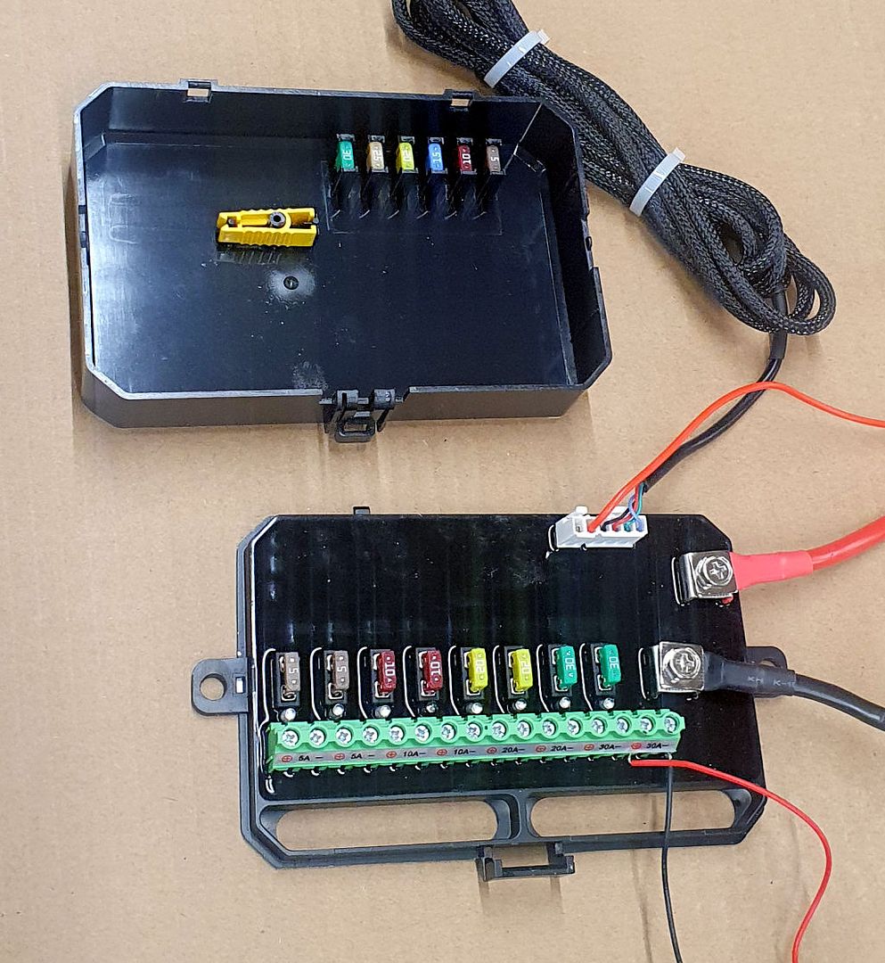
A closer look at the control unit.
The control unit is all solid state and all of the electronics are "potted" to protect them from the environment. There are six outputs, and the total load across all six must total 60 amps or less. The instructions say "the maximum output current of 1 & 2 is 30a and the maximum output current of 3-8 is 20a." They don't say why, but my assumption is that the semiconductors passing the power through outputs 1 and 2 are more highly rated than those on outputs 3-8. A table in the instructions shows the maximum amperage recommended for each output so that information should be followed when assigning devices to the outputs.
I connected everything on the workbench. Instead of an automotive battery for this test, I used a benchtop power supply. I connected a small LED pod to output 1 for this test. One feature I really like is an LED that will light when the fuse in that circuit is blown (see the diagram above). Another nice feature - there are spare fuses and a fuse puller inside the cover of the control unit, so if you're in the field and need a fuse, you've got them. In this next photo circuit 1 is switched on, powering the LED pod. The benchtop power supply is out of the picture to the right:
Auxbeam has a video on their web site showing how everything gets connected, including a demonstration of the unit controlling multiple lights:
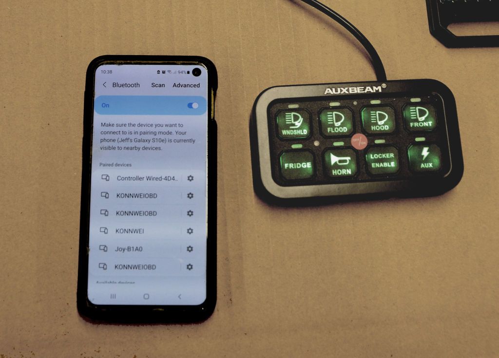
With the initial test done, I tried to use the app to configure and control the switch panel. Initially I had some trouble getting the switch panel app to talk to the switch control. Every Bluetooth device I've ever connected to with my Android phone required that the device be paired with the phone first in order to use it, so I paired the phone with the switch panel but I couldn't get the app to work. This works differently - if you first pair the device with the phone, the app will not be able to connect to the switch panel. The procedure is:
- Turn on Bluetooth on the phone.
- DON'T pair the switch panel with the phone.
- Open the app and tap the Bluetooth icon (left photo below).
- Turn on Bluetooth in the app (center photo)
- When the switch panel appears, tap the word "connect" (right photo).
After getting this to work, I tried the same on the iPhone. Based on what I learned with the Android, I didn't try to pair the iPhone with the switch panel, I just followed the procedure above and the app connected just fine. I've suggested to Auxbeam that they update the instructions to say that pairing is not required - many people, who are accustomed to pairing Bluetooth devices before they use them, will probably pair the device first like I did and will not succeed in getting the app to connect to the switch panel.
With the app working, a quick test controlling one of the circuits from the app:
Features of the app include:
- Turn circuits on or off
- Change the color and brightness of the switch backlighting
- Change the labels and names on the switches on the switch panel image on the phone (but not on the switch panel itself). Photos can be used as switch labels.
- Change the operation mode of each switch:
- On/off
- Momentary (useful perhaps for something like a horn)
- Pulsed (can turn a light into a flasher, perhaps for first responder use)
- Grouping switches. Multiple switches can be grouped to operate together. Useful if the amperage of the devices to be turned on exceeds the capacity of one circuit in the panel.
I went through all the features of the app and was going to do a video showing them all, but the features are shown very well in this video from Auxbeam so I'll link to that instead of doing my own video:
Installation in a Jeep first involves deciding where to mount the switch panel and the control unit. Brackets are provided for both, and they may or may not be needed depending on where you decide to mount things.
One place the switch panel can mount nicely is to the windshield frame trim panel above the mirror. In the left photo below I'm holding it up there in my JKU. Mounting it in the same place in the TJ looks pretty much the same, so I didn't include a TJ photo.
The right photo shows my phone in the holder it lives in when it's in the Jeep. Since the unit can be controlled directly from the app on the phone, one option would be to not mount the physical switch panel anywhere. It probably should be plugged in for all the circuitry to operate properly, but it could be stowed somewhere (under the seat?) and everything controlled from the app on the phone.
Using the phone as the switch control might also be useful for turning things on or off from outside the Jeep - for example, at a camp site. From your chair next to the campfire you could turn on or off the campsite area lighting you've got attached to your roof rack.
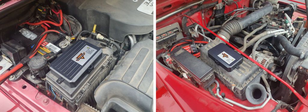
The control unit is probably best mounted under the hood to keep the high power leads short. On the left below, I've set the unit on top of the JK's TIPM. It fits nicely there and clears the hood when closed. On the right, I've set it on top of the air cleaner box. Both of these locations would make for a simple installation, but there may be other places in the Jeep's engine compartment that suit your needs better.
Once the mounting is decided, the wiring is straightforward. A fuse tap is installed in the Jeep's fuse panel to provide switched power, the high power leads are connected from the battery to the control unit through the supplied 60-amp circuit breaker, and the switch panel wires are routed though the dash and connected to the switch panel. Once that's done, devices can be connected to the outputs of the control unit.
I experimented with the different switch modes (on/off, momentary, pulsed) and grouping switches and found the various options to work as advertised. For my use, I probably won't need those options, but I'm sure people will find uses for all of the options.
At about half the price of an SPOD (less than half if you factor in the $135 SPOD Bluetooth option) this switch panel is well worth consideration. And if you don't need the Bluetooth capability, Auxbeam has 6 and 8 switch panels available without Bluetooth that are less expensive (the six switch non-Bluetooth unit is on their web site for about $140 as I write this).
The switch panel can be found at:
https://auxbeam.com/products/ar-800-multifunction-rgb-switch-panel-system-qp008526
On last tip: Customizing the switch panel - if the 60 supplied switch labels don't provide what you need to label your switches, you can make your own labels. Earlier this year I reviewed a six-switch panel from Auxbeam, it doesn't have Bluetooth control and is different in a number of other features, but the switch labels are the same and in that review I described how to make custom switch labels in case you need a label that isn't provided in the kit. The same technique can be used to make labels for this panel:
https://expeditionportal.com/forum/threads/barn-door-for-jk-factory-hardtops.127687/post-2942757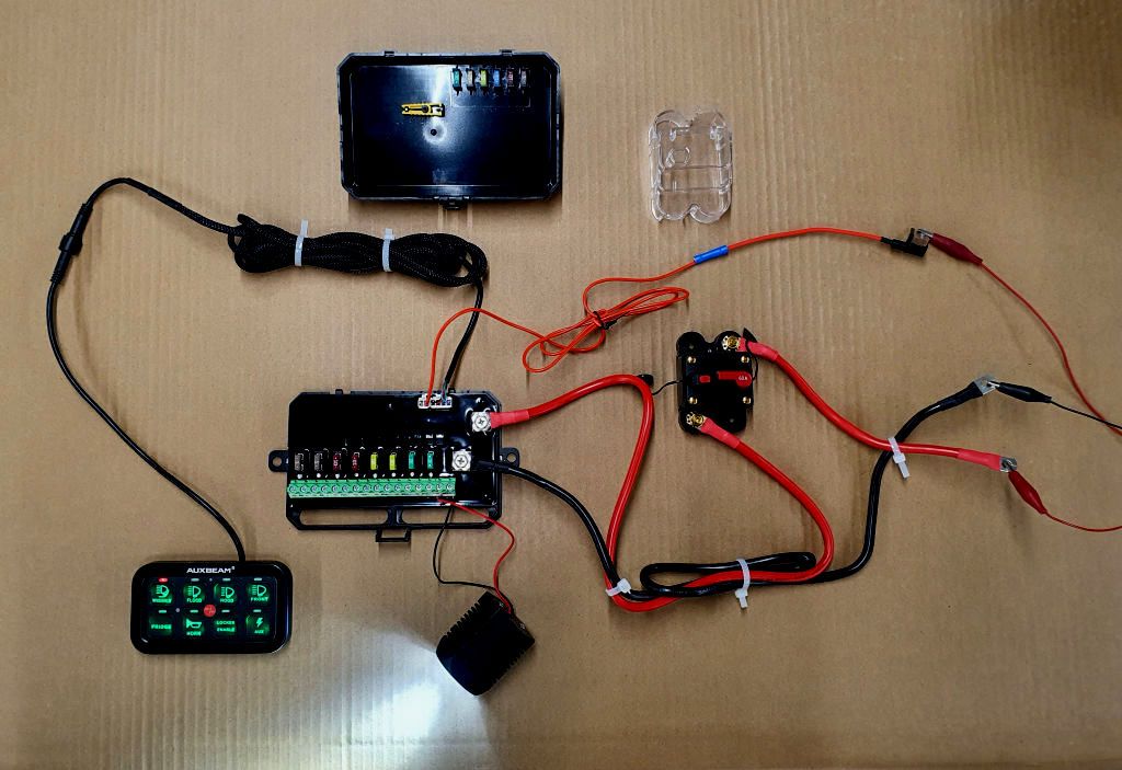
.jpg)
