tacozord
Adventurer
Wow- definitely some nice write ups here. Much to take away.
Thank you. I appreciate the compliment, and I hope that some of this information is of help to you.
Get your tickets to THE BIG THING 2026!
Wow- definitely some nice write ups here. Much to take away.
Nice work! I love how well documented and photographed all of your mods are, not to mention how clean they all are. Any reason you didn't choose to get a swing out tire gate?
I debated this decision for months before making the purchase. On the one hand, I really wanted a swing out to accommodate a tire, gas can and hi-lift. But in the end, I concluded that my wheel base was so long that i didn't want the extra length and mass hanging off the back. I hope I don't regret it.
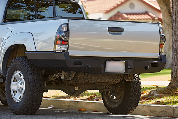
I recently installed my new Pelfreybilt High Clearance Rear Bumper for my 2015 Toyota Tacoma. This was a rather straight forward installation, but you definitely need a helping hand to lift it into place.
I planned on taking a lot more detailed pictures along the way, but due to time constraints, I overlooked many steps. Overall, I think you'll get an idea of what was involved.
-----------
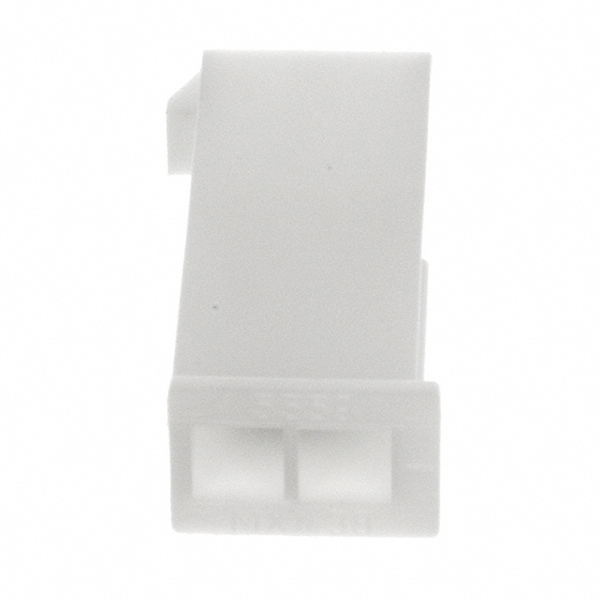
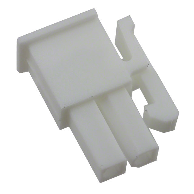
The first step was to disengage the electrical. There were two plugs for the license plate lights. I simply turned them ninety degrees and pulled them out of their light housing. Next, I unbolted the trailer socket and removed. I then cut off all of the wiring harness zip-ties that attached it to the bumper and trailer hitch.
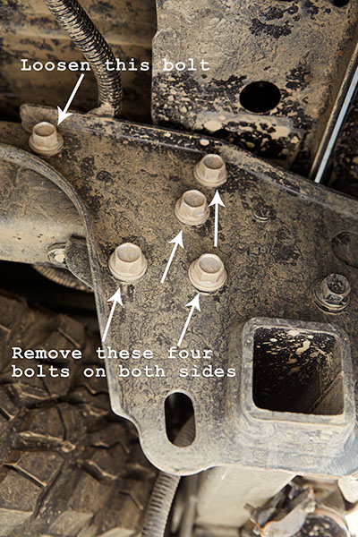
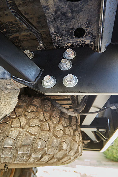
Next, I removed the old bumper. On each side, there were five bolts attaching the bumper and tow hitch assembly. I only removed four and left the top-most bolt loose. I did this to aid in removal of the old bumper as well as installation of the new one.
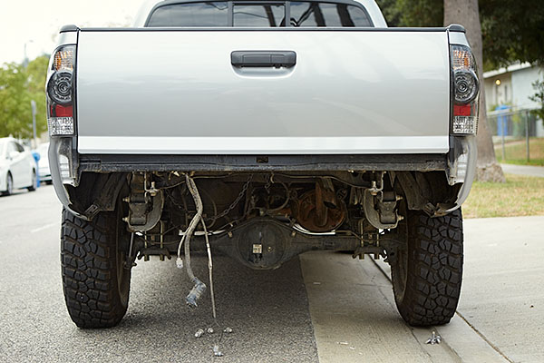
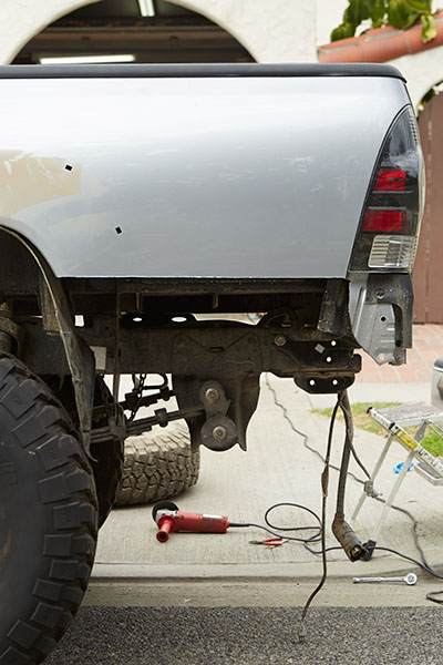
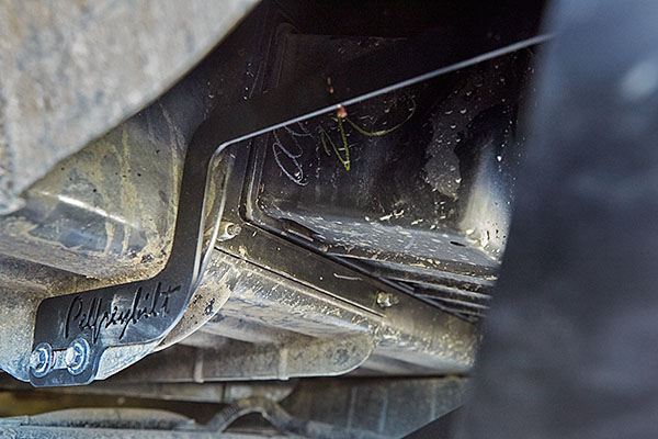
It looked like this before removing the bumper.
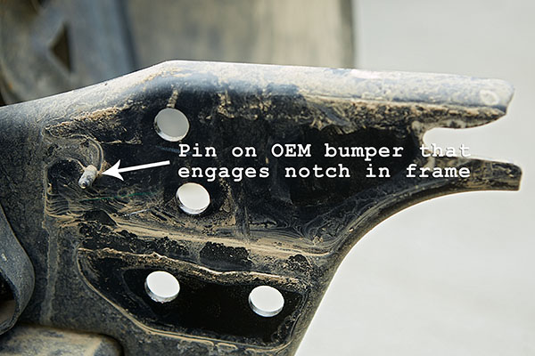
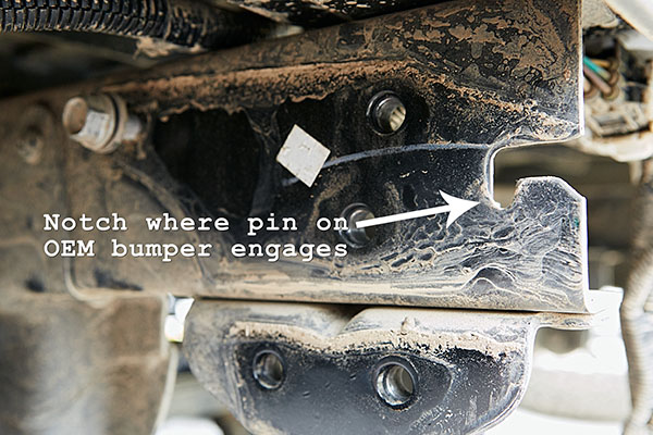
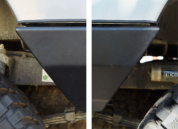
There is a pin on the bumper that engages in a notch on the frame. So in order to remove the bumper, I needed to lift it up and pull towards me on each side.
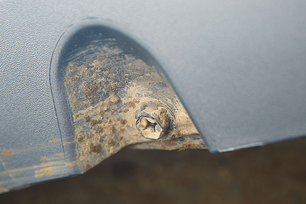
Once removed, you can see the pin on the bumper.
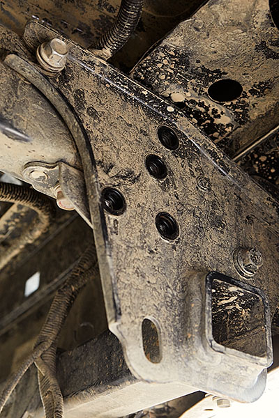
And this was the notch on the frame that the pin sat in.
With the bumper removed, it was time to move on.
The next step was to remove the fender flares. I began by removing the bolts on the underside of the flare that attaches it to the bedsides.
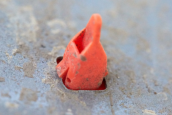
Then, the tricky part. Don't just pull on the fender flare to remove it. You'll easily damage the plastic retaining clips. Instead, I reached up behind the fender flares and removed the plastic retaining clips with needle-nose pliers. I just squeezed the little tabs and pushed them through. The difficult part is reaching them all. All I can say is, "Contorted body positions and strained neck."
By the way, there are two types of clips, orange and blue. The only difference is in their sizing with the orange ones being slightly larger.
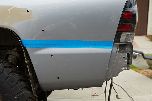
With the fender flares removed, it was time to mark and cut the bedsides. I used blue painters tape and marked a line on it. I measured down from the bottom edge of the bed cap with a flexible tape ruler so that my line was 1/2" below the tail light. This ended up being 16-3/4".
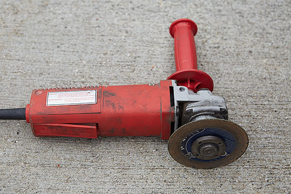
I used the following angle grinder with a 4-1/2" x 1/16" cut-off wheel. If you notice, I used the handle on the back side of the grinder. This was intentional. I held on to this handle and used my knuckles up against the beside as a support guide. I worked slow and steady by first scoring a line and then taking a second pass to cut all the way through.
When done, I had a ton more clearance. Aside from the straight cut, I needed to eye-ball the cut below the tail light. At the back of the straight cut, just below the tail light, the line turns in towards the center of the vehicle for about an inch and then sweeps down in an arc.
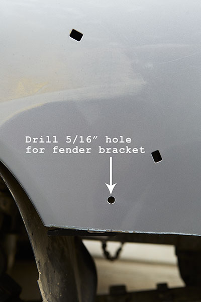
Next, I needed to attach the fender support brackets. I marked and drilled a 5/16" hole.
I used the supplied hardware to attach the bracket. This can be adjusted later to position the bedsides to your liking.
At this point, I installed the bumper temporarily. Lifting the bumper in place is really a two person job. I placed the center-point on a hydraulic jack, lifted it up, and maneuvered it into place with the help of a friend. By leaving the top-most bolt threaded, we used that as a support point while we inserted the additional bolts.
As excited as I was to see the bumper installed, I couldn't torque them all the way. I first needed to evaluate my cut line, which needed a slight trimming. Once satisfied, I removed the bumper, trimmed, and used an 80-grit flap disc to smooth and de-burr the edge.
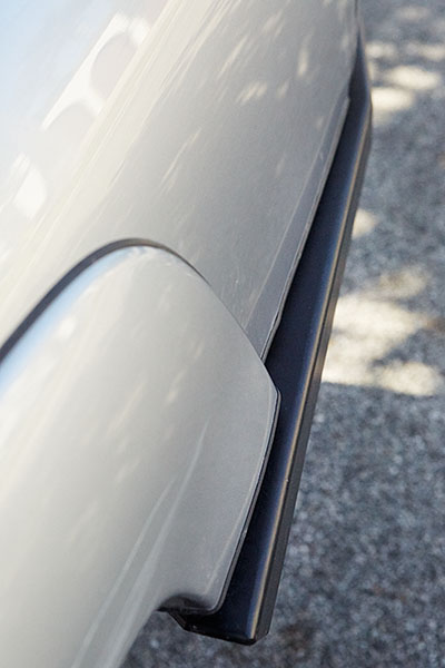
Before re-installing the bumper, I installed the fender flares, marked, and cut them to be in line with the bedsides. Then I painted the exposed edges of metal with primer. At this point, I should have installed the rubber molding, but I made the mistake of installing after the bumper was in place. Although I was successful, it would have been much easier had I done it beforehand.
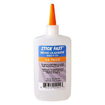
To hold the rubber molding in place, I used Stick Fast CA Glue. I first attempted to use a two-part epoxy, but it would have taken me too long. I had some CA glue available, so I thought I'd try. Luckily, I had the option of thickness to choose from, thin, medium or thick. I figured the thick consistency would be the best. It worked like a charm.
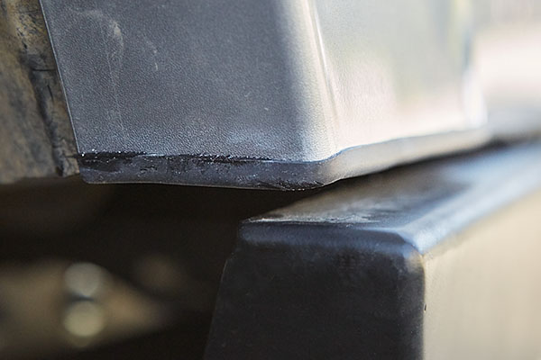
Installing the molding after the bumper was a bit challenging, both to my patience and the final fit. In the end, I made it work and was satisfied with the look.
The instructions stated that the next step was to remove the black plastic trim pieces that wrap around the body below the tail light. I did so, but wonder in hind sight if this was really necessary. It appears that there's enough room to keep them in place.
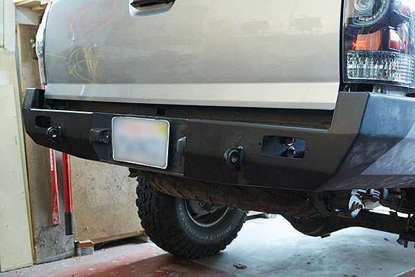
Anyway, it was time to permanently install the bumper. The final installation is relatively easy, but aligning the bumper was a bit frustrating. I really wanted the front point of the bumper to perfectly line up with the fender flare. Unfortunately, I was unsuccessful. This was the best I could to do without cutting the bolt holes on the bumper.
The bumper is designed to stick out from the bed sides to accommodate the fender flares. I adjusted the fender support brackets to align the fender with the outside edge of the front point of the bumper. It just needed to be pleasing.
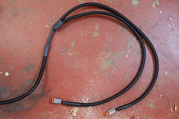
There were several remaining items to complete the job: trim the fender liner, install the license plate lighting, re-connect the electrical connections, and install the flip up license plate holder.
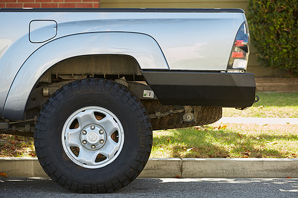
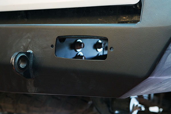
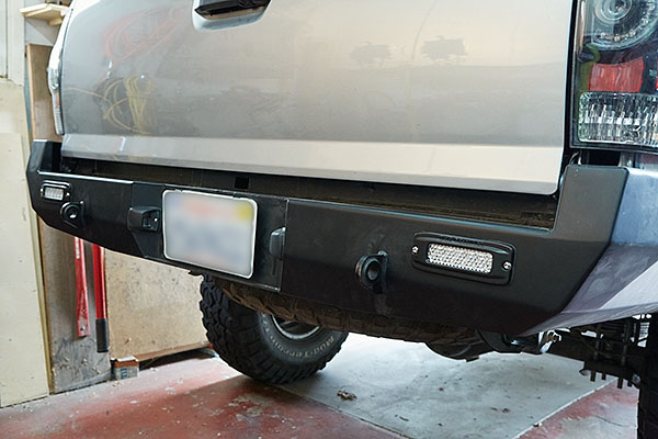
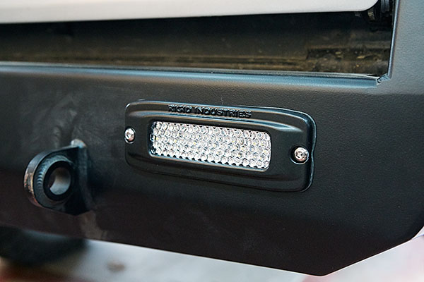
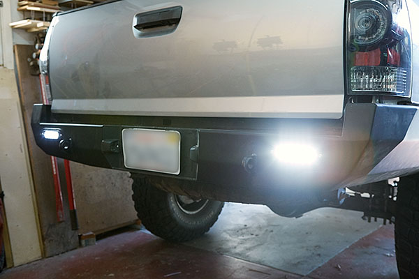
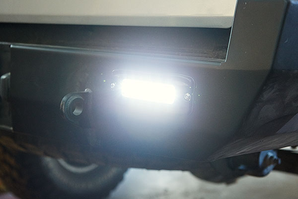
The installation was complete and looks great! If you notice, my bumper has cut-outs to accept rear-facing lights. I'll be tackling this project soon.
Even with the spare tire mounted underneath, there is a lot more clearance than before.
Overall, I'm very pleased with the bumper. Now, it's time to go beat it up.
Looks awesome man, I also didn't install the trim molding when the bumper was off.
My problem was in packaging for some reason it got overlooked and I didn't get it with the bumper.
Satin sent it over night but by that time the bumper was already on.
Can you give me any pointers..? I'll be trying to install my trim molding tonight or tomorrow. Did you use any special tool to slid it in..? Thanks..!!
For me, the high clearance was a must! I had already smashed my trailer harness, bumper, bed side, and tail pipe. I only wish I had it sooner.Just inquiring as I'll be facing a similar decision in the not too distant future. At the moment I'm leaning towards the swing-out for the pure utility. But then again I'm torn between doing a traditional bumper or a high-clearance so clearly offroad prowess isn't #1 at the moment.
I used a combination of a flat head screw driver, a 1" putty knife, and CA glue. The screwdriver was used as a lever to push the molding up and hold it in place. The putty knife was used to open the molding. I would slide this down the slot in the molding as I pushed up with the screwdriver, which is levered off the bumper. Periodically, I'd squeeze in some glue and wait for it to set before moving on. I found the glue was necessary on either side of a corner, because the bend would make it want to pull off. If you go slow, you'll be fine. Just know that it will test your patience.
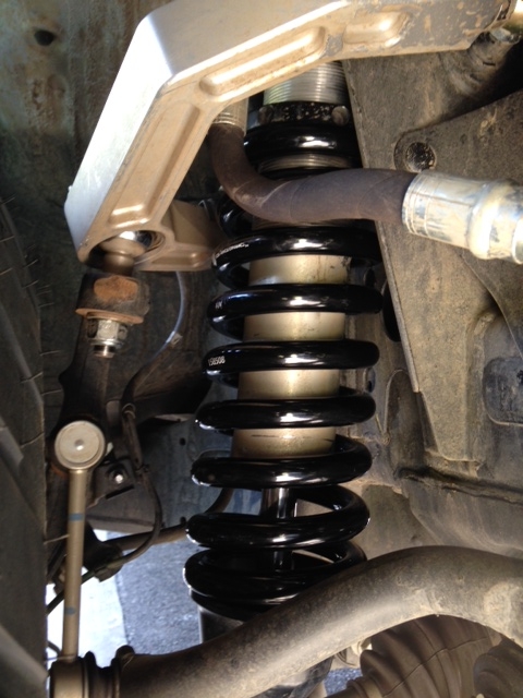
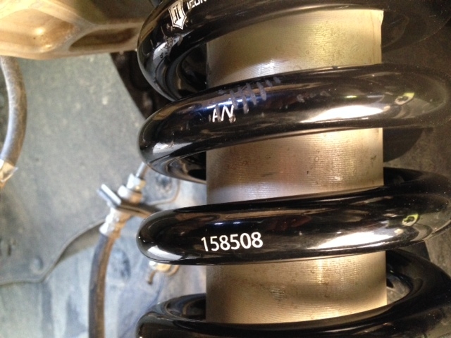
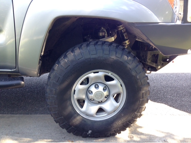
When I ordered my Icon suspension, I requested 700lb springs. However, they were delivered with 650lb springs. Well, I finally got them and installed on 3/4/15.
I'm also thinking of going with this same set up.
I know it was asked but, how do you like the #700 springs now that you've had them for a bit..?
Icon tells me that the truck needs to have more than 200Lbs for the #700 springs.
All I can say is that I don't have a problem with the heavier springs. In fact, there's been several times where I've hit the bump stops when driving fast and hard on a bumpy road.
So...it's given me the correct ride height without preloading the springs and it seems to handle bumpy terrain acceptably despite the few hard hits. I'm happy with them and wouldn't change anything at the moment.