Eighteen...
Eighteen…
(above) Getting another early start… When the work is this fun, it’s hard to stay away…
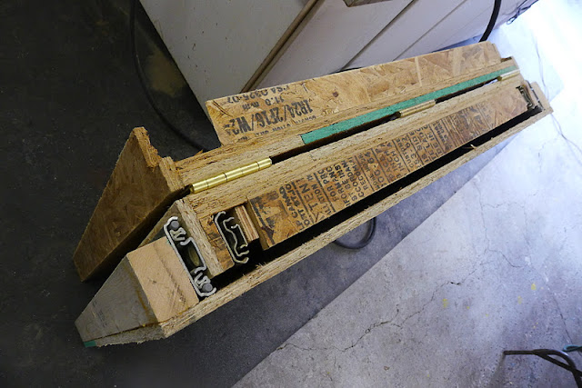
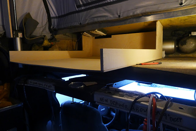
(above) Starting easy, scrub sand the epoxied drawer from yesterday…
(above) Now, time to work on getting the electrical system closer to back up and running…
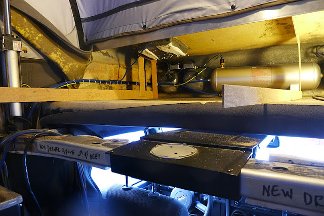
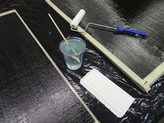
(above) Today’s field of play…
(above) The inverter has the gauge and outlet removed from the unit and they will be relocated to the plywood cabinet… The push-on connectors in the middle of the picture are the 120 volt power leads to the newly extended outlets… I solder 99.9% of all my electrical work… It takes just a bit longer than crimping connections but is without question the better way to make shorter wires longer, or to join two (or more) wires together… I like doing things better…
(above) The inverter is mounted to a piece of plywood… The fit of the plywood to the cabinet with the inverter mounted is tight…
I put the factory yellow face plate on the inverter and it would not swing into the cabinet with it on… Missed by 5/32”… No way, that way…
Take it back to the bench… Remove all fourteen miniature screws that hold the cover plate on, remove and set aside the yellow plastic thing, go back to the Jeep, hold the plywood / inverter close and figure out what’s needed to have it fit… Typical for this kind of work… Frustrating…???… No… You just accept it to be this way and you do what it takes to make it work, whatever…
To have it work, the leads for the gauge and the ‘power out’ need to go out the top of the case…
Bring out the step drill, get a plastic sleeve, get the wires through and test fit, again… Works…
(above) Back to the bench, tape and heat shrink the wires together, then get the cover plate and all fourteen of the fruit fly size screws back into the inverter… Fun, with fingers the size of hot dogs… Just for laughs, try it sometime…
(above) This side of the ‘power lead’ will go into a small screw clamp connector (that I don’t have yet)… I have three sets of wires that will connect together and want a simple way to remove the connection, so the inverter panel can be removed semi-easily if it ever needs to come out… I solder the straight ends of the wires, so the screws in the connectors get a better ‘bite’ into soldered wires… You will not find an un-soldered wire-end in my work…
(above) To get the 120 volt ground back to the inverter case (as it was when the outlet was case mounted) I stripped the insulation off the middle of the green wire, twisted it hard, formed a loop around needle nose pliers and soldered the loop… That’s what you see screwed to the inverter case, the ground wire leading from the outlet mounted to the plywood then going up to the other outlets up high… If you look close you’ll see that this is in the middle of a wire, not just an end loop…
(above) The new wiring harness has multiple soldered connections with shrink tubing insulators, then taped together with friction tape…
The space within the battery / inverter compartment is Tight with a capital T… Loose wires going all over the place are bad, so these minimal wiring connections is something that will be much appreciated later by me putting it back together and to whoever might have to work on it in the future…
(above) Another look at the wiring… Notice the ground lead from the case to the outlet, to the other outlets… What I was talking about above… There is enough loop in the wire for the outlet to still come off the case, but not too much to junk-up the interior…
Again, this is what custom looks like…
(above) I want to put a 12 volt outlet on the back plywood panel as well, but the mounting nut for the outlet is too long given that I’m using 1/2” plywood, so the extra mounting nut is cut away with shears… Once that was done the connection went together easily…
(above) Then it was back to the Jeep to connect the loose ends…
(above) Then the inverter panel was put in place… This is looking down into the compartment…
(above) See what I was saying about tight…???…
(above) Stepping back, you see the new outlets… 120 volt AC and 12 volt DC off the back… Nice to have for when you really want easy power access to the outside… Not part of the original scope of work, but I saw the need and just did it…
The T-nuts are for mounting, without worry, the inverter… Wood screws might loosen and having that thing loose would be bad… Avoid the bad I always say…
For your information, that electrical work took about six hours…
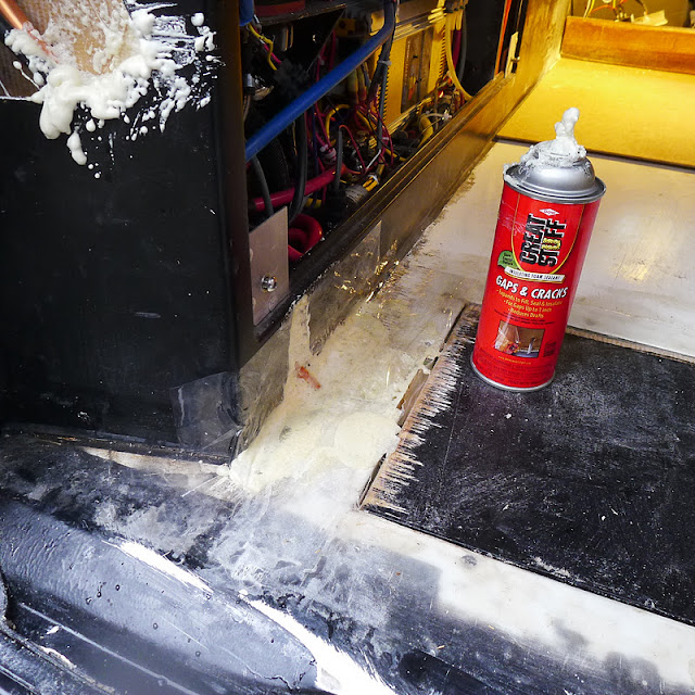
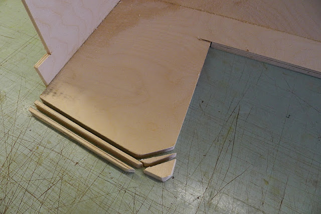
(above) Back inside Jeepster… This just looks wrong… The frayness of it all… So I sanded the fiberglass, wiped it wet, spread some Poly-U adhesive then…
(above) … put this 1/8” plywood and Teak curb in place…
(above) Then it was fiberglassed / epoxied it in place…
Now the back cabin floor is isolated from the front… Forget about water or other stuff rolling forward to fall under the seats… now the rear cabin is like a big shower pan…
It also will be a natural curb for the teak floor (which will be removable) to bump up to… Hit the brakes hard and it won’t shift forward…
I also fiberglassed the floor to cabinet base-line… Now it is waterproof and further makes the new work tie seamlessly to the existing cabin / floor…
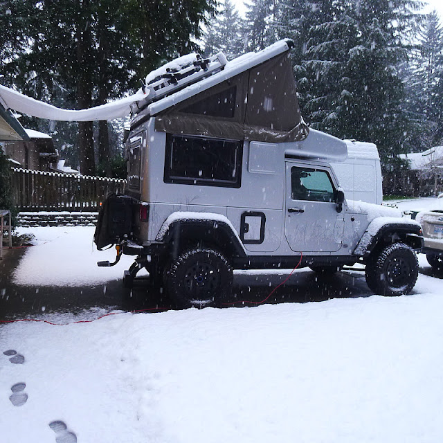
(above) At the end of a long day, a long week, I slowly closed up Jeep Earth Roam Deluxe, and thought about all that happened this week, and smiled a tied smile…
Time for a beer…
More later…


")