FG buildup

dhackney

Expedition Leader
Thanks to everyone who has contacted me regarding the CG / roll center, etc.

I did find an error in my inputs. Once I corrected that input the model lowered the CG to 72.28" / 183.59cm.

I located another model at:
http://www.kettlemorainemotorsports.com/cg.html

I ran the numbers through that model and it returned exactly the same values as the Jeep model.

Unless both models are identically flawed, I am assuming these to be valid for a static 3 point pivot frame, i.e. level load.

I am researching pivot tables that we can put the rig on and get an empirical measurement of the roll angles. I think that is probably the only way we'll ever know for sure where we are at with the 3 point pivot frame against the stops on either side.

I edited the previous "weigh-in" post to correct the values and calculated data points.
 

dhackney

Expedition Leader
Some further thoughts on the CG / roll angle test.

Tom has pointed out to me that if our rig was a solid block of mass, with no voids and of a completely consistent matter, the CG would be about 72”, or halfway up through the mass. This is just one more reason why I find if very hard to believe that our CG is 72” high.

If I make even slight alterations to the Jeep model that allow for even a small portion of the liquid rearward transfer or rearward suspension weight shift during the lift the CG drops to ~60” / 152.4cm and the roll angles increase to > 30 degrees.

My conclusion is that our CG is probably well below 72” / 182.88cm, probably closer to or well less than ~60” / 152.4cm.

I believe that in order for the Jeep model or others to be used accurately a much more rigorous approach must be taken to the test. I tried to be as accurate as I could with the front axle height measurement but I question the validity of the results of this model unless you take the additional steps of eliminating liquid transfer and the insertion of solid rods to eliminate suspension expansion/compression.

Due to the 3 point pivot frame, I believe our roll angles can only accurately be measured on a tilt table. I continue to seek that opportunity and will post the results if I can conduct that test.

I am currently unaware of any expedition vehicle with a 3 point pivot frame that has undergone a tilt table test, but would welcome those results if any are available.


My methodology for the lift was:
1. Locate and mark the horizontal centerline of front axle. This ensured I would always be using the loaded tire radius for the calculations. Since both tires are the same circumference, I didn’t have to worry about averaging those as you would on a race car set up for stagger.
2. When we lifted the front axle by driving it up on the tilt bed, I used the mark on the front axle and a laser level to obtain the lifted front axle centerline height of the loaded front tires.
3. I did not replace the shocks with solid bars to eliminate suspension height change, as this would have been impractical in my circumstances. I made no allowance for the compression of the rear suspension, the corresponding lift of the front suspension and the resulting weight transfer rearward.
4. I made no allowances for the shift of liquids in the tanks, specifically the fuel tanks, which are long and narrow. The estimated 185 lbs. of fuel in those tanks would have shifted towards the rear.
5. I only took one measurement and one weight at one height.


Test conditions:
• Fuel tanks: ~25 gallons. The tanks are saddle tanks located under the garage along the frame rails. Equal amounts in both tanks via a crossover. There are no baffles, so this weight would have all shifted back. That’s 180 lbs @7.2 lbs/gallon.
• Raw water: ~35 gallons. The tank is mounted between the frame rails aft of the garage. No baffles. That’s 291.5 lbs. but since the tank was ~75% full there would have been minimal shifting.
• Fresh water: 33 gallons. The tank is mounted under the dinette, left side of camper centerline, aft of the rear axle. Full load, 100% full. That’s 266.56 lbs.
• Gray water: 0
• Black water: 0
• Front axle centerline, static: 14.375” / 365.13mm
• Front axle centerline, raised for test: 42.875” / 1,089.03mm
• Amount front axle centerline raised for test: 28.5” / 723.9mm
• Front contact patch elevation raised for test: 28.5” / 723.9mm
• Front track: 71.75
• Rear track: 79
• Wheelbase: 154

On the front axle lift amount, I had previously contacted the author of the Jeep spreadsheet and asked if I needed to go higher than 24” since our FG was a longer wheelbase. He responded that any higher lift would not significantly improve the accuracy of the model.

Doug
 

dhackney

Expedition Leader
I adapted the Jeep Center of Gravity (CG) XL model so you can enter weight and weight shift to rear axle data and see the corresponding change in CG / Roll Center / Roll Angles / etc. to our FG data set.

The model demonstrates how relatively tiny amounts of weight shift make a very large difference in the CG.

The model is at:
http://www.hackneys.com/mitsu/docs/CG-model-hackneyFG.htm
 

dhackney

Expedition Leader
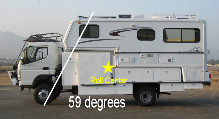
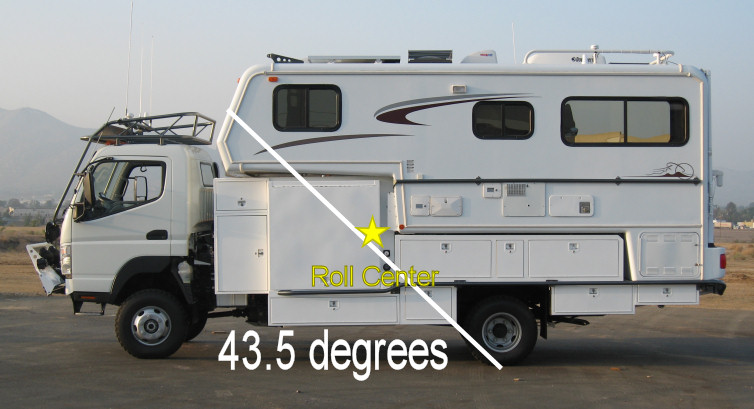
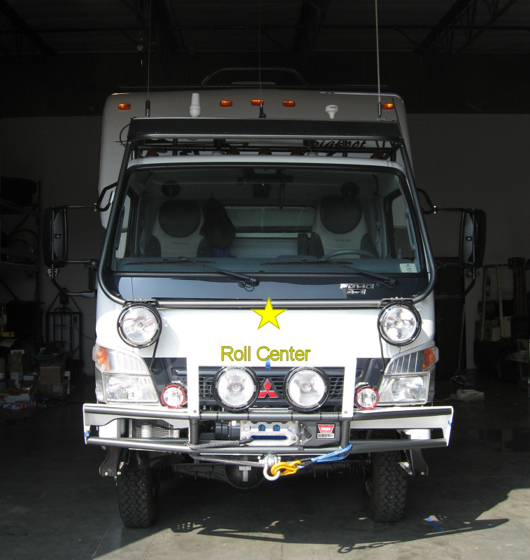
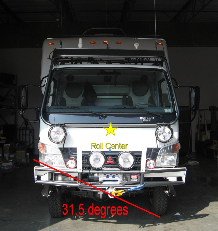
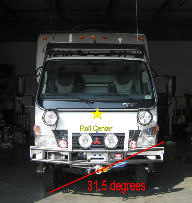
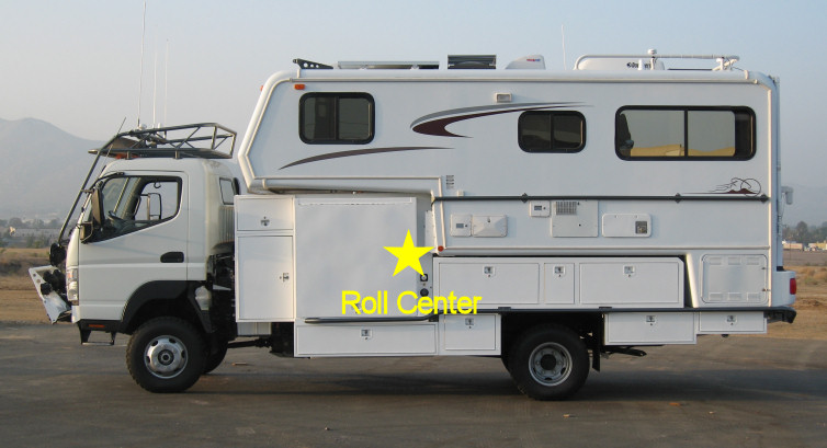
Revised roll center photo comps based on latest estimates of weight shift data.

These revised calcs are based on a very minor (relative to vehicle weight and weight of fluids) allowance for rearward shift of liquids and suspension travel during the tilt test.

CG is probably lower, but I'm going to stay conservative. R&L roll angles are based on front track. Values using the rear track are ~two degrees higher. Due to the 3 point pivot frame for the camper & rear storage boxes, I don't think there's any way to know the real roll angles until we get it on a tilt table.

CG: 58.92" / 149.66cm high, 98.14" / 249.28cm behind front axle centerline
Roll angle left: 31.12 degrees
Roll angle right: 31.56 degrees
Roll angle back: 43.48 degrees
Roll angle forward: 59.02 degrees

roll-center-side-view-02.jpg


roll-center-side-forward-02.jpg


roll-center-side-back-02.jpg


roll-center-front-02.jpg


roll-center-front-left-02.jpg


roll-center-front-right-02.jpg
 

Bob_Sheaves

Observer
Counterpoint from an OEM vehicle dynamics specialist

The above is a perfect example of "a little knowledge being dangerous".

"Roll center" is defined as ( http://en.wikipedia.org/wiki/Roll_center ):

"The roll center of a vehicle is the notional point at which the cornering forces in the suspension are reacted to the vehicle body." -taken from the military (and later SAE) Suspension Engineering Handbook

What is being calculated above is NOT the roll center, but the center of gravity of the vehicle. In a Hotchkiss suspension, as used in the 4x4 Fuso, the roll axis is simply a line drawn through the axle to spring interface from the left to right springs and the particular suspension roll center is where this line crosses the vehicle lateral centerline. Then a line is drawn through this point from the front suspension to the same point for the rear suspension. This resultant line is the actual roll axis for the vehicle. The CG of the vehicle is then connected to the vehicle roll axis by a normal line (not vertical, necessarilly) through the CG. This becomes the moment arm the mass of the vehicle acts upon the vehicle handling dynamics.

There are far more points of failure in the "backyard" method of approximating (and not very accurately, at that) the tipover of any vehicle than this method is capable of determining. See "Multi-Leaf Spring and Hotchkiss Suspension CAE Simulation" at http://www.simulia.com/download/sol...ferences/chassis_mulitleaf_auc02_chrysler.pdf for a more definative answer than is possible here.

The point of this comment is NOT to denegrate this builder, but to point out that there MAY be some very deadly omissions this user is not aware of. Consultation with a professional engineer, trained in vehicle dynamics would have removed all uncertainty, and provided a legal backstop against the shown modifications and potential liability.

Best regards,

Bob Sheaves
CEO
catNET Incorporated
http://www.catnetsolutions.com
 

FusoFG

Adventurer
Bob,

What are you saying?

That that the term Roll Center has been used incorrectly? I agree, but I don't think any claims are being made by the builder about high speed cornering stability.

I assume the builder knows that darting in and out of traffic on the 405 in rush hour at freeway speeds is going to be dangerous.

If by your reference to the wikipedia article you are saying:

"Load transfer is of critical importance for vehicle stability in vehicle such as SUVs...... In a steady state .... is only related to the position of the center of mass above the ground, the track width and the lateral acceleration. SUVs must shift their center of mass lower or decrease their lateral acceleration to avoid tipping...."

I agree with that also.

If by saying:

"There are far more points of failure in the "backyard" method of approximating (and not very accurately, at that) the tipover of any vehicle than this method is capable of determining"

you mean the effects of tire flex, suspension movement, free surface effects of the fluids in tanks, fluid shift between the tanks (I personally don't like the cross connected fuel tanks) and the errors in estimating those effects.

Not to mention the dynamic effects of dropping the downhill wheel in a hole, driving an uphill wheel over a bump and turning uphill to avoid an obstacle while tranversing an off camber shelf road.

I agree again.

But I hope the vehicle manufacture has taken all that into consideration when it said in it's body buider manual "the center of gravity height should not exceed 60 inches ....".

I think the builder is just attempting to determine where his vehicle fits within those requirements.

If you know a more accurate method of measuring the center of gravity I would appreciate hearing it.

I know it's difficult to make changes after the fact, but if there was any concern about the center of gravity height I would:

1. remeasure with all tanks full to eliminate the effects of fluid shift.

2. consider remeasuring with, as some methods suggest, the shock absorbers replaced with rigid links.

3. consider not using the bigfoot water tank (higher) and instead use your in frame water tank (lower).

4. Stow gear if possible to put light things (tp, paper towels, etc) up high and heavy things (pots, pans, tools, etc) down low.

5. consider removing (or moving) any unnecessary or luxury items from the cab roof and camper roof (roof rack, a/c, etc).
 

Bob_Sheaves

Observer
Please see my inline comments.... in bold:
FusoFG said:
Bob,

What are you saying?

That that the term Roll Center has been used incorrectly? I agree, but I don't think any claims are being made by the builder about high speed cornering stability.

The point I was making is, not that the term is being used incorrectly, but rather that the concept of what the gentleman appears to be thinking he is measuring (an assumption on my part, I admit, due to the wording and methodology used) is actually, nothing of the kind. High speed cornering is not the issue either, but rather the side slope ability of the chassis and suspension to keep the vehicle from "turning turtle" on it's own at ANY speed.

I assume the builder knows that darting in and out of traffic on the 405 in rush hour at freeway speeds is going to be dangerous.

If by your reference to the wikipedia article you are saying:

"Load transfer is of critical importance for vehicle stability in vehicle such as SUVs...... In a steady state .... is only related to the position of the center of mass above the ground, the track width and the lateral acceleration. SUVs must shift their center of mass lower or decrease their lateral acceleration to avoid tipping...."

I agree with that also.

Again, speed is not the issue, but the side slope capability is.

If by saying:

"There are far more points of failure in the "backyard" method of approximating (and not very accurately, at that) the tipover of any vehicle than this method is capable of determining"

you mean the effects of tire flex, suspension movement, free surface effects of the fluids in tanks, fluid shift between the tanks (I personally don't like the cross connected fuel tanks) and the errors in estimating those effects.

Not to mention the dynamic effects of dropping the downhill wheel in a hole, driving an uphill wheel over a bump and turning uphill to avoid an obstacle while tranversing an off camber shelf road.

Not only correct, but your list is fairly inclusive. The missing pieces are tire slip angle, tire carcass stiffness (I assume this is what you were aluding to in the comment re: "tire flex"), static weight transfer reaction and dynamic weight transfer reaction in 3 axis measurement.
I agree again.

But I hope the vehicle manufacture has taken all that into consideration when it said in it's body buider manual "the center of gravity height should not exceed 60 inches ....".

That 60" dimension is an overall approximation, given the primary design direction for the vehicle, 80/20 highway/off highway use in commercial service. That is why I say the entire battery of calculations and tests SHOULD be performed to ensure the occupants safety and knowledge of the new design limits of the revised package (vehicle, it's contents, and it's operational considerations).
I think the builder is just attempting to determine where his vehicle fits within those requirements.

If you know a more accurate method of measuring the center of gravity I would appreciate hearing it.

For measuring the CG-no-that is adequate, BUT it is not the only parameter. The moment arm associated with it cannot be measured directly-it can only be calculated by direct measurement of the vehicle suspension roll axis, NOT just the roll axis of the front or rear by itself. That PDF I referenced has more detailed info.

I know it's difficult to make changes after the fact, but if there was any concern about the center of gravity height I would:

1. remeasure with all tanks full to eliminate the effects of fluid shift.

2. consider remeasuring with, as some methods suggest, the shock absorbers replaced with rigid links. ABSOLUTELY CORRECT

3. consider not using the bigfoot water tank (higher) and instead use your in frame water tank (lower).

4. Stow gear if possible to put light things (tp, paper towels, etc) up high and heavy things (pots, pans, tools, etc) down low.

5. consider removing (or moving) any unnecessary or luxury items from the cab roof and camper roof (roof rack, a/c, etc).

As I stated before, I am NOT trying to say anyone did something "wrong", I am saying that not enough research and calculation, as well as understanding of the operating parameters, was done, not through intent, but rather, a lack of knowledge of what it takes to design a vehicle.

Best regards,

Bob Sheaves
CEO
catNET Incorporated
http://www.catnetsolutions.com
 

dhackney

Expedition Leader
Bob,

Thank you very much for your informed and detailed comments.

My goal with this thread and our web site is to leave a trail that others may follow, specifically to learn from our mistakes as complete novices heading into this project.

I agree that I was under-researched for this project. I believe that a minimum of 24 months would be required for an undetaking of this nature. Due to our last minute switch from a sailboat and our resulting timeline requirements I only had about 90 days from "we need to use a four wheeled land vehicle" to selecting the FG/camper design.

I was unable to identify any qualified resources to perform an engineering analysis of the type you describe before, during or after this project. I would welcome your referral to any resources who are capable of the measurements and calculations you mention and recommend.

Specifically, I am interested in getting the vehicle on a tilt table so we can accurately determine our ultimate CG/roll angle/whatever the correct engineering term is with the 3 point pivot frame in operation.

During our tests we had the vehicle reviewed, including test driving off road, by an experienced expedition vehicle consultant, who has extensive experience in the design and implementation of current market vehicles. I encourage this step as a minimal process for those doing custom builds. We made several design changes based on our consultant's input, all of which dramatically improved our vehicle's on- and off-road handling characteristics.

I applaud your efforts to shine some light of knowledge and experience into this area. Those of us who are forced to, through lack of available market offerings, or choose to create our own vehicles of this type could profit greatly from knowing more about the parameters you describe.

In our project we attempted to keep as much mass as we could as low as possible and located between the frame rails if possible. The execptions to this design goal, which will be typical systems in projects such as this, include the diesel genset and two of the house batteries.

We were also limited by the factory camper we ended up with, as we lacked the opportunity of optimally locating systems for a lower center of gravity, etc. that those who build a custom camper box are afforded.

Thanks again for your input. I believe your comments to be valid and continued input of this type can only serve to make future projects better engineered.

Doug
 

dhackney

Expedition Leader
FusoFG said:
fluid shift between the tanks (I personally don't like the cross connected fuel tanks)

Tom,

The cross connect line between the fuel tanks includes shutoff valves on each tank. Our methodology is to shut those valves when we are heading off-road.

The dual tanks enabled us to keep our fuel load as low and as close to the center line of the vehicle as possible, while also offering the opportunity to keep the fuel load equally spread on the chassis.

For dynamic effects while the valves are open the fuel load shift is limited by:
- valve state (i.e. closed, partially open, fully open - normal is fully open, partially open would achieve our purpose of fuel capacity and dual side filling while limiting fuel load shift)
- size of the cross connect line
- amount of air space in the receiving tank (air will compress)
- size and throughput capacity of the breather lines for both tanks (one sucking air in as fuel drains, the other expelling air as the fuel flows in)

For transients, I believe the effects of the cross connect line to be minimal. For extended exposure on a side hill, with the potential effects of downhill wheel drop into a hole, uphill wheel on a rock, etc. that you mentioned, I believe the effects could be significant depending on the factors cited above.

Doug
 

Bob_Sheaves

Observer
Please see comments inline...in bold:
dhackney said:
Bob,

Thank you very much for your informed and detailed comments.

No problem, I love working on trucks and vehicles of all kinds....so much it's been a career that is so intense I am STILL far from a "know it all"....LOL.

My goal with this thread and our web site is to leave a trail that others may follow, specifically to learn from our mistakes as complete novices heading into this project.

Very commendable, I am sure many will learn from your site.

I agree that I was under-researched for this project. I believe that a minimum of 24 months would be required for an undetaking of this nature. Due to our last minute switch from a sailboat and our resulting timeline requirements I only had about 90 days from "we need to use a four wheeled land vehicle" to selecting the FG/camper design.

As a sidebar here, it takes most OEM's about 3-4 years to fully design and develop a commercial cab and chassis...no joke. There actually IS that much work to ensure "it" is a safe and economical vehicle that meets the customer's needs. SOmetimes we miss, sometimes we hit the target exactly.

I was unable to identify any qualified resources to perform an engineering analysis of the type you describe before, during or after this project. I would welcome your referral to any resources who are capable of the measurements and calculations you mention and recommend.

I will not recommend myself, as I feel it is unethical for me to solicit business on a hobby board. Therefore, I would recommend using Google search terms " vehicle suspension consulting engineer" which will return the names of many individuals and companies that provide this very service. Some are Mr. Herb Adams in Detroit, Mr. Andre Reynard, and others.


Specifically, I am interested in getting the vehicle on a tilt table so we can accurately determine our ultimate CG/roll angle/whatever the correct engineering term is with the 3 point pivot frame in operation.

Ohio TRC (Transportation Research Center), NATC (Nevada Automotive Test Center), and others all have commercially available test centers for just this type of work. Not cheap, but you would get the same service that the OEMs receive.These centers are quite well versed in this type of analysis, especially NATC (I had a lot of fun there when I was working with the military vehicles for AMGeneral).

As a sidebar to this, if you are looking to determine what the amount of frame twist is in the FG, you should ask about a wave course test-this is a test where the vehicle is driven over a series of concrete half cones in the roadway that are 3' tall at the outside edge opposite the next cone. The purpose of this is to make the axles and suspension travel to the jounce (upper travel limit) and rebound positions opposite at each end of the vehicle. In other words, the left front tire would move to it's lowest position in travel, the right front would be in it's highest position, the left rear tire would be in it's lowest position, and finally, the right rear tire would be in it's highest position. What this twist does is to maximize the amount of travel the frame flex and suspension is capable of, without turning the vehicle over (ideally, if the design is correct, the body will be perfectly level in this position). If the body is not level in this test, you can see directly where the "binding up" of the vehicle is occuring.


During our tests we had the vehicle reviewed, including test driving off road, by an experienced expedition vehicle consultant, who has extensive experience in the design and implementation of current market vehicles. I encourage this step as a minimal process for those doing custom builds. We made several design changes based on our consultant's input, all of which dramatically improved our vehicle's on- and off-road handling characteristics.

I applaud your efforts to shine some light of knowledge and experience into this area. Those of us who are forced to, through lack of available market offerings, or choose to create our own vehicles of this type could profit greatly from knowing more about the parameters you describe.

Thanks for the kind words, but remember that even with 30 years of doing this job, I STILL do not know everything. That is why I can design and predict in a computer (experience tells me what is generally valid) BUT testing is ALWAYS required to verify what I thought would work, actually does.

In our project we attempted to keep as much mass as we could as low as possible and located between the frame rails if possible. The execptions to this design goal, which will be typical systems in projects such as this, include the diesel genset and two of the house batteries.

We were also limited by the factory camper we ended up with, as we lacked the opportunity of optimally locating systems for a lower center of gravity, etc. that those who build a custom camper box are afforded.

Thanks again for your input. I believe your comments to be valid and continued input of this type can only serve to make future projects better engineered.

Doug
Best regards,

Bob Sheaves
CEO
catNET Incorporated
http://www.catnetsolutions.com
 

dhackney

Expedition Leader
Joaquin Suave said:
I can only bite my tongue for so long.

Doug wrote


What is the use!

Other are as likely to listen to you...As you were likely to listen to me!

Joaquin wrote last November:


Maybe its time to go use your truck rather than obsess over the fact that you overbuilt! All the calculations in the world are not going to change that fact. Better luck next time.

Joaquin,

When you made your post we did have a thumbnail weight, and a series of weight slips from scales. We made continuous design changes throughout the project regarding systems and materials based on the results from component, system and vehicle tests.

As to your advice, with all due respect, if we took every single piece of advice we've received on this project we'd have ended up with a camel, a.k.a. a horse designed by committee. We had a design goal and a set of criteria that can be very hard for others to relate to. While we have been open to input, and have incorporated much input from many parties, it was necessary to stick to the essential criteria, else we could have ended up with something cobbled together that led nowhere.

I'm sure we'll end up like you, shedding gear as we go along. You'll probably be able to locate us by following the trail of discarded items.

The CG testing, data gathering and calculations have been included in our project plan since day one. The purpose is to know, to the greatest extent possible, what the operational parameters of our rig are. Do you know where your CG is, or the roll angle limits for any dimension of anything you've ever built, are building or plan to build? I think those things are good to know, especially with a 3 point pivot frame that dynamically changes those parameters as you are moving. If you feel knowing that data has no value, then we will need to agree to disagree on that point.

My goal with this thread and our web site remains the same: that others can learn from what we've done right and from our mistakes. I believe it adds value to the community to openly share all the aspects of the project, including all the screw-ups. I think people learn more from what didn't work out than from a carefully edited compilation of all the things done right. If you feel that goal is of no or little value we will have to agree to disagree on that point.

I believe the people with experience and expertise who have regularly provided input into this thread during the duration of the build have added tremendous value to this project and to those that will follow. Comparitively, I see much less value in a solitary post near the beginning of the project followed by a 20/20 hindsight / Monday morning quarterback post in the closing days.

Specifically related to your assertion, if you felt so strongly that we were overbuilding, why were you not regularly posting that opinion or emailing me with your opinions? You've obviously got a wealth of experience and hard earned knowledge. Why not share it regularly and repeatedly, especially with rookies and neophytes? You are in a position to greatly aid those who are entering this field of interest. I hope you have the opportunity to do so in the future.

And better luck next time to you, as well, on your new project, and I am not saying that in a negative way. I hope you are successful in applying all of the lessons you have learned over the years and that your new rig fulfills everything that you feel your previous attempts lacked.

As to using the rig, you would be hard pressed to find anyone who is more anxious to get going than we are. We're not just parked here twiddling our thumbs. As John Prine said, "if lighting were desire, this house would have burned down a long time ago."

Be well,
Doug
 

Forum statistics

Threads
188,394
Messages
2,904,139
Members
230,274
Latest member
mbauerus1
Top