Isuzu npr 4wd

gator70

Well-known member
I do some composite failure analysis as part of my day job. Part of this is interfacing composite parts with traditional metal structures. I can say with certainty that many failure modes are not intuitive, even to engineers with classical training. Load transfer is also highly dependent on the composite panels stiffness in each loading direction. Paying for good engineering is often worth the cost. Unfortunately this isn't an area where you can just do a high level copy of something that "works". The first step in a decent design is good data on the composite panels. This includes the stiffness (modulus), allowable strain in each loading type, thermal expansion characteristics, and concentrated load allowables. Once you start asking, you will find many composite panel suppliers do not have most, or any of this data. Ideally from actual qualification testing, but conservative numbers from basic calculations can substitute.

All that said, adding additional material (increasing the stiffness) of an attached metal structure can be counter productive, resulting in higher peak/concentrated loads. This isn't something I would want some recent engineering grad working on, thats for sure! In fact its often best to design a attachment with weak points. Better to have a bolt shear or fail in tension, then have a composite panel fail in buckling or pure bending. Of course the failure modes need evaluated for safety.

Depending on the stiffness of the box/composite, and its allowable ultimate loads, a subframe can be made quite light. Say a 14ft box in the 5,000-7,000lb range could be less than 400lbs. In these cases the subframe serves as a locator, and it spreads out loads. With the box itself providing the vast majority of the structure. This is the most efficient way, as a good composite panel will have much higher specific stiffness.

Most if what you say is correct. In the four season designs the weight is greatly increased by all heavy items installed within. (my panel thickness is 55mm)

And with the background you state, I would love to see delamination tests if available. As the xps core is not that strong.

Other builders use marine plywood and attach the material in the core, then with blind fasteners try to feel good about subframe attachment, with about 4000lbs of eight foot wind sails.

Where I live we have 70 mph crosswinds. (Santa Ana winds)
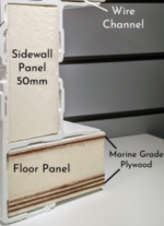
1761271595583.png
 
Last edited:

luthj

Engineer In Residence
And with the background you state, I would love to see delamination tests if available. As the xps core is not that strong.

Every manufacturer has their own secret sauce so to speak. So any data, even if I had it for your approximate material, isn't going to line up with the specific panel you have. If you want that data, get it from your panel supplier. I don't work with vehicle panels like the one here (aerospace is my area of expertise). However even if I did, sharing such information with someone who doesn't appear equipped to use it... That would be irresponsible.

Foams can have their density adjusted to easily provide 40-100psi of tensile strength. Bonded plywood will spread a fastener point load out over a large area. It would not be difficult to design a setup where the limiting factor is the fastener, not the foam or adhesive bond.

The strength of the foam matters, but having a stiff bonded skin transfers the load over a large area. The amount of area the load is effectively spread over is a function of the sandwich stiffness. Failure can be from adhesive shear-out, tensile failure of the foam, or buckling.

You repeatedly talk trash about builders using blind fasteners and plywood (probably total composites), but have yet to post a single bit of math or testing. Forgive me if I don't take such claims seriously.

Without knowing the specifics of the materials I will refrain from comment of feasibility, except to say I can easily see a number of situations where the setup you so deride, would be more than sufficient for vehicle loading. In fact the way you talk about this subject indicates to me that you lack fundamental understanding of how to perform dynamic design analysis.

Analyzing a bolted joint in composites isn't rocket science (well, except for when it is, but I digress).
 

rruff

Explorer
And with the background you state, I would love to see delamination tests if available. As the xps core is not that strong.
XPS...who?

Other builders use marine plywood and attach the material in the core, then with blind fasteners try to feel good about subframe attachment,
Again, who? If that's TC they have a square FG tube bonded inside the panel, and the bolts blindly fasten to a thick steel plate.
 

gator70

Well-known member
I'm pretty happy with these discussions. As there is no once source to locate perfectly accurate information.

Looking back on my engineering decisions, and the information I can gather. For me, I made the right decisions.

My adult son who is a PHD in structural engineering from a German University helped me too.
 
Last edited:

mog

Kodiak Buckaroo
Other builders use marine plywood and attach the material in the core, then with blind fasteners try to feel good about subframe attachment, with about 4000lbs of eight foot wind sails.

Where I live we have 70 mph crosswinds. (Santa Ana winds)

View attachment 899496
Your ignorance lack of full knowledge shows. The used (without authorization photo) tccr.png
does not show the attachment method, which DOES NOT rely on the plywood for attachment. There (in my case) is 3 inch steel square tubing bonded in the floor with full length 1/4 steel plate inside running the full width as anchor points. TC has 'extra' plywood in the floors as their bodies are also used in commercial applications and rolling a hand truck with a refrigerator across it certainly is more stress then an 'overlander' walking to the galley to make a sandwich. (Disclaimer, I don't have a Phd in engineering, so just a guess)

Your time/focus might be more productive completing your Chinese box and getting on the road to test your designs, instead of trying to slam other individuals or companies to make you feel better about your design/product.
 

gator70

Well-known member
My welder seems to do really good work. I would love to learn more about this so I can check the work. Does anyone have resources for me to get educated on this? Not as a professional, more to be a good quality control person. My need is to look for issues that might fail later.
 
Last edited:

SkiFreak

Crazy Person
My welder seems to do really good work.
Welders get certified by proving that the welds that they do meet the specified standards required. This is usually done via x-ray or destructive testing as part of the certification process.
With most welding it generally comes down to penetration, which cannot be seen by simply looking at the weld. However... I have seen many welds that I could pretty much guarantee were crap!
Contamination within the weld is another issue, if preparation is poor. This too cannot be easily seen by the naked eye.

If you are getting structural welding done by anyone that is not a certified welder in that specific area of welding, be it on your own head.

Does anyone have resources for me to get educated on this?
How can you become a welding QA person?
Start by spending many years in the welding trade, so you have an idea of what you are looking at.
 

SkiFreak

Crazy Person
My adult son who is a PHD in structural engineering from a German University helped me too.
As much as there are numerous crossovers, structural engineers focus on static, stationary structures, while mechanical engineers design systems that involve motion.
Just saying...
 

gator70

Well-known member
As much as there are numerous crossovers, structural engineers focus on static, stationary structures, while mechanical engineers design systems that involve motion.
Just saying...
His PhD thesis was about design techniques for offshore wind turbines that are evaluated and discussed, with a focus on two primary types of structural failures: fatigue and ultimate strength.

So moving parts.
 

gator70

Well-known member
Welders get certified by proving that the welds that they do meet the specified standards required. This is usually done via x-ray or destructive testing as part of the certification process.
With most welding it generally comes down to penetration, which cannot be seen by simply looking at the weld. However... I have seen many welds that I could pretty much guarantee were crap!
Contamination within the weld is another issue, if preparation is poor. This too cannot be easily seen by the naked eye.

If you are getting structural welding done by anyone that is not a certified welder in that specific area of welding, be it on your own head.


How can you become a welding QA person?
Start by spending many years in the welding trade, so you have an idea of what you are looking at.

I very much appreciate the information

When I worked in NASA engineering I learned even the most analyzed engineering required, "redundancy"
 

gator70

Well-known member
Boy do these rigs need a long list of equipment to be stored. Do I really need a expensive 12v air system, as originally planned? I have a small 110 VAC 100psi compressor.
 

mog

Kodiak Buckaroo
Boy do these rigs need a long list of equipment to be stored. Do I really need a expensive 12v air system, as originally planned? I have a small 110 VAC 100psi compressor.
You probably should do some testing ahead of time. Being 110 VAC you will not even need it mounted on your rig. There is a big difference between running one tire up from being low at 20psi to 38 psi (or whatever your 'road psi' is) and trying to fill 4 tires you deflated to 15 psi up to that same pressure. Most small electric pumps (AC or DC) will overheat after X amount of use and will need a long cool down period. Also tire size is a huge factor. Even using my semi-huge shop compressor there is a significance difference between airing up the 35s on my F-250 and the 40s on my Ram.

While not a recommendation, I use the MorrFlate TenSix and they have quite a bit of information on their page regarding CFM, duty cycle, tire valve style/limitations, etc, that you might find informative. LINK
 

gator70

Well-known member
You probably should do some testing ahead of time. Being 110 VAC you will not even need it mounted on your rig. There is a big difference between running one tire up from being low at 20psi to 38 psi (or whatever your 'road psi' is) and trying to fill 4 tires you deflated to 15 psi up to that same pressure. Most small electric pumps (AC or DC) will overheat after X amount of use and will need a long cool down period. Also tire size is a huge factor. Even using my semi-huge shop compressor there is a significance difference between airing up the 35s on my F-250 and the 40s on my Ram.

While not a recommendation, I use the MorrFlate TenSix and they have quite a bit of information on their page regarding CFM, duty cycle, tire valve style/limitations, etc, that you might find informative. LINK

Yea, I evaluate the small 100 psi 110 vac compressor. Normally costs $60 new. Fits in my storage compartment. And my habitat has an external 110 vac outlet. I had planned a two piston 12v compressor. Mostly priced at $200. Now I look at this alternative. I already own the two tire tube(s) and filling gauge. Thanks for the comments - I'm A newbie with the needs of onboard air.

Note: I have a big expertise with motors in equipment from China (90% of all goods). The brush's on the motor armature wear out in six months on all motors then lose power. Whether that is vacuum, a air compressor or most motor based China equipment, they all have this problem.
 
Last edited:

Forum statistics

Threads
190,565
Messages
2,929,227
Members
234,224
Latest member
V45W_Proto2.5
Top