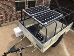
I built a 3 axis coupler. I had a design brewing in my brain that used 3 point hitch parts, specifically, the pins since they are so strong. Then I ran across jscherb’s post and his design. Yeah, his is a lot better.
I used a little bit of my design, most of it is his, but I changed a couple things on his that might be better/easier? You can judge.
I used a 1 1/4” pin as my hitch pin, instead of Jeff’s 1” bolt. Not sure I’d do it again, but it was my design, so I wanted to try it. It’s strong. Stronger than any ball since the diameter is larger than any ball shaft. I had to open up the hitch hole to fit the pin. I welded a thick collar to the bottom as my plate to take the friction of turning. As it wears down, I can just adjust the height of the pin with the bolts.
Iused a 1 1/4” bushing drilled through the 2x2 square tubing. To house the pin. The height of the pin is adjustable to be flush with the pin that keeps it on.
I opted for a 1” pin holding the shaft to the hitch. I just felt better about the strength of it. Plus, my mig gun had a problem and I had to TIG it. I’m not very good at TIG yet and wanted a bigger pin to weld to.
The two areas I deviated from Jsherb’s idea was the ball to the 2x2 tubing. Instead of grinding the ball to fit, I heated up the tubing and flared it out to accept the ball. I’m sure it’s just as easy/strong to do it his way.
I also think he set up his 1” bolt with the head still on it. Slide all parts on before you start welding. I cut the head off, welded that end to my 1” bushing and slid the parts on one at a time. When I was done, I snugged the nut down to where the ball just moved Freely, then welded the nut to keep it from spinning off.


