You are using an out of date browser. It may not display this or other websites correctly.
You should upgrade or use an alternative browser.
You should upgrade or use an alternative browser.
Pretty Ugly... 1835, The Build Begins
- Thread starter Madoxen
- Start date
joeblack5
Active member
Best wishes for Jemima, it is ashame that that happened while working on a project together. My wife once jumped out of the bed of our truck, while helping me unload, landed twisted and tore her ACL.
I am very curious how you are measuring the location of the several pivot joints on your truck..
Johan
I am very curious how you are measuring the location of the several pivot joints on your truck..
Johan
Madoxen
Active member
J is doing well but life is hard with only one arm working properly . She is tough and getting on with what she can untill it can be fixed.
Hope your wife healed quickly after doing her ACL.
It took me a very long time when i broke my cruicia ligament in my knee just aboit wrote off a year for that blunder.
Hope your wife healed quickly after doing her ACL.
It took me a very long time when i broke my cruicia ligament in my knee just aboit wrote off a year for that blunder.
joeblack5
Active member
Not quickly... Acl was replaced ..but not as good as the original...
Is the cab of the truck a three point being as short as the cab part is?
I can not find a lot of literature about these design. Sofar only " overland camper" by Steve Wigglesworth.
It would seem that the connection points change slightly depending on the load on the frame itself.
Looking forward to seeing your approach.
Johan
Madoxen
Active member
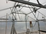
Well so close yet still along way to go before i can get the truck in here . Managed to get the legs all concreteted and the vent racks cut back so they dont turn the truck into a shiesh cabab
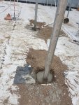
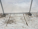
Still need to move the 4 vent motors and wireing. Make a 4mtr tall 3mtr wide door. And tidy up all loose ends.
Oh and white was the walls and roof to stop some heat and light as it truely is blinding in there with the sun in full force.


Still need to move the 4 vent motors and wireing. Make a 4mtr tall 3mtr wide door. And tidy up all loose ends.
Oh and white was the walls and roof to stop some heat and light as it truely is blinding in there with the sun in full force.
Madoxen
Active member
Got a little closer to getting Pretty Ugly under cover this week. But having a much needed weekend off from any kind of work.
Had to weld up some extra supports for thw skin and doors to hang on.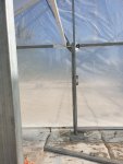
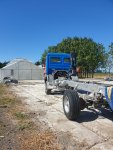
Then we used the little forklift to lift up the rear end of the truck and push it about 200 meters so it was next to its future home
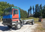
Here she is looking at her new home but unfortunatly we can open up the front wall untill i have buult the doors to seal it otherwise a good wind woyld destroythe rest of the skins
Had to weld up some extra supports for thw skin and doors to hang on.

Then we used the little forklift to lift up the rear end of the truck and push it about 200 meters so it was next to its future home

Here she is looking at her new home but unfortunatly we can open up the front wall untill i have buult the doors to seal it otherwise a good wind woyld destroythe rest of the skins

Last edited:
Madoxen
Active member
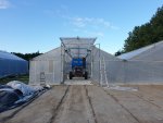
Well after one last push on the doors of the new work shop i managed to get the truck under cover but it was very tight through the door frame, so tight in fact that i ended up removing both the side mirrors although this was partly to do with having almost no control of the truck which was being moved by the little forklift.


Madoxen
Active member
well it has been quite a while, Covid has nearly destroid us twice financially and came with in a nats whisker of having to sell alot of stuff we would not want too.
that asides we are all well and healthy baring shoulders and shingles lol.
All of that is not why you are here, Pretty Ugly has sat there for quite a while gathering cobwebs :-( and looking unloved but we have now had a little time away work to do some more on her.
1st up was lots of graphity on the chassis marking out where the frame and hab box etc needed to go along with exact points for the pivot and fixed points.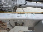
then I finished making up the moc sub frame pivot points and outer rail.
This was to allow me to get within the ball park for the longatudinal line the pivot points will follow and also to give me an idea where the Floor of the habitat box will go whilst being pivoted

and with the rails

one this was done and both the pivot points had been drilled at dead center of the chassis I cleard out an access path to the rear of the truck and used the forklift to lift the rear left wheel to simulate the torsional twist

Slowly all the way to 530mm with both pivots in the middle point.
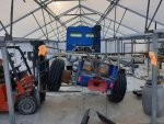
It all looked good at this point and we thought we had nailed it 1st try to we dropped the truck back down to the ground and removed the rear pivot pin and lifted the truck again to see if there would be any change...
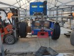
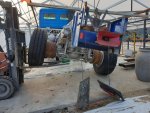
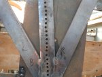
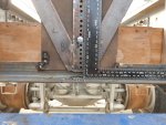
In the above image once we took the pivot pin out as you can see the hole was 25mm out of line which would most definitely end in breakages.
with the above photo we needed to drop the rear pivot by 12 holes (the whole that intersected the center line of the back plate) which ment the pivot was going to be below the bottom of the chassis. after a little head scratching we decided to lift the middle pivot point by 6 holes and drop the rear point by 6 holes and start again see =ing how close this would get us to the longitudinal pivot line.
all was going well untill there was a massive pop and twang, so I jumped off the forklift and checked everything over which turned out to be one the the spot welds on the rear right corner letting go. I scratched my head again and looked about untill I had one of those DUH moments yes I had dropped the rear hole by 6 holes drilled it and put a new pin in but in my hast I had forgotten to remove the original pin lol 2 pins led to a fixed rear pivot point and an exploding spot weld. well the system works as if it dont pivot right even when only 200mm lifted at the rear wheel it pops welds. anyhow I removed the extra pin and re-welded the busted spot.
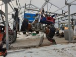
The end result after multiple lift and drops is a longitudinal line that is near enough there to give me a starting point to weld up the frame and be close enough to fine tune the height of the pivots
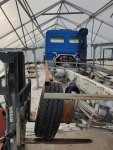
The last few lifts were just Over 600mm high from the right side center ( left tyre )of the bottom of the rubber wheel from the ground.
this still left alot of space (failed to measure it but visually looked like 40mm or so)before the subframe would interfere with the top of the chassis rail.
that asides we are all well and healthy baring shoulders and shingles lol.
All of that is not why you are here, Pretty Ugly has sat there for quite a while gathering cobwebs :-( and looking unloved but we have now had a little time away work to do some more on her.
1st up was lots of graphity on the chassis marking out where the frame and hab box etc needed to go along with exact points for the pivot and fixed points.

then I finished making up the moc sub frame pivot points and outer rail.
This was to allow me to get within the ball park for the longatudinal line the pivot points will follow and also to give me an idea where the Floor of the habitat box will go whilst being pivoted

and with the rails

one this was done and both the pivot points had been drilled at dead center of the chassis I cleard out an access path to the rear of the truck and used the forklift to lift the rear left wheel to simulate the torsional twist

Slowly all the way to 530mm with both pivots in the middle point.

It all looked good at this point and we thought we had nailed it 1st try to we dropped the truck back down to the ground and removed the rear pivot pin and lifted the truck again to see if there would be any change...


In the above image once we took the pivot pin out as you can see the hole was 25mm out of line which would most definitely end in breakages.
with the above photo we needed to drop the rear pivot by 12 holes (the whole that intersected the center line of the back plate) which ment the pivot was going to be below the bottom of the chassis. after a little head scratching we decided to lift the middle pivot point by 6 holes and drop the rear point by 6 holes and start again see =ing how close this would get us to the longitudinal pivot line.
all was going well untill there was a massive pop and twang, so I jumped off the forklift and checked everything over which turned out to be one the the spot welds on the rear right corner letting go. I scratched my head again and looked about untill I had one of those DUH moments yes I had dropped the rear hole by 6 holes drilled it and put a new pin in but in my hast I had forgotten to remove the original pin lol 2 pins led to a fixed rear pivot point and an exploding spot weld. well the system works as if it dont pivot right even when only 200mm lifted at the rear wheel it pops welds. anyhow I removed the extra pin and re-welded the busted spot.

The end result after multiple lift and drops is a longitudinal line that is near enough there to give me a starting point to weld up the frame and be close enough to fine tune the height of the pivots

The last few lifts were just Over 600mm high from the right side center ( left tyre )of the bottom of the rubber wheel from the ground.
this still left alot of space (failed to measure it but visually looked like 40mm or so)before the subframe would interfere with the top of the chassis rail.
Last edited:
Madoxen
Active member
Madoxen
Active member
I did not get a chance to put the forklift back to the truck to float the center pivot yet but i have been trying to work things out in my head...
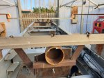
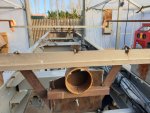
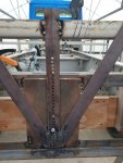
In the below picture you can see by the markings T M B on both the horizontal frame and the vertical pivot holes that depending on where the pin is it will force the subframe to either travel more or less in the horizontal plane when the frame rail hits the chassis stop. The top pivot moves the least and the bottom pivot moves the most.
Now think about the fact the middle pivot joint is set at the T position and the rear pivot is at the B position which should result in the frame bowing in the center to the left but instead it is bowing ever so slitely to the right.
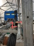
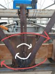
My thoughts on this are that i am not on the nutral pivot point. And that the rear pivot is moving the the lower pin to the left ( its below the nutral point) as the hole chassis twists and the middle upper pivot is moved to the right as its above the nutral point. Both of these movements are enough to offset the travel of the frame from the 1st part above.
Illustrated in the below thumbnails
As a sidenote from the above i have found out that the average amount of twist needed for an expedition vehicle is 3 degress per peter of chassis measured from the fixed point to the end rocker/pivot point so 16.5 degrees for a 5.5mtr chassis.
In the below picture you can see by the markings T M B on both the horizontal frame and the vertical pivot holes that depending on where the pin is it will force the subframe to either travel more or less in the horizontal plane when the frame rail hits the chassis stop. The top pivot moves the least and the bottom pivot moves the most.

Now think about the fact the middle pivot joint is set at the T position and the rear pivot is at the B position which should result in the frame bowing in the center to the left but instead it is bowing ever so slitely to the right.
My thoughts on this are that i am not on the nutral pivot point. And that the rear pivot is moving the the lower pin to the left ( its below the nutral point) as the hole chassis twists and the middle upper pivot is moved to the right as its above the nutral point. Both of these movements are enough to offset the travel of the frame from the 1st part above.
Illustrated in the below thumbnails


As a sidenote from the above i have found out that the average amount of twist needed for an expedition vehicle is 3 degress per peter of chassis measured from the fixed point to the end rocker/pivot point so 16.5 degrees for a 5.5mtr chassis.
Last edited:
Dear Madoxen, my two cents:
I think you are doing it wrong, sorry. The fixed tandem points should be in the center and the longitudinal pivots one in the front and one in the rear end, as the original and proven diamond shape. Twisting the frame will always lead the precious and elusive central pivoting line to the sides, the farther you go, the more the gap between a straight desired line and reality. Shortening the distance between the fixed points and the longitudinal pivots will shorten the gap. You will never find a perfect center pivoting line, but you can get close to it if doing so.
You can also expect some up and down and side to side movements in the central fixed points, and that is why they are sometimes mounted in rubber. I think it is a good idea, but I have also seen many trucks without rubber interface and they go pretty well.
In addition, it seems better to have two rougher connections of the Box right on top or near the rear axle to cope with the axial dynamic loads.
Just give it a try profiting that the gear is right there.
Cheers and keep going.
Pairoa
Madoxen
Active member
Hi Pairospam, please dont be sorry, i welcome all thoughts ideas and theories.Dear Madoxen, my two cents:
I think you are doing it wrong, sorry
The fixed tandem points should be in the center and the longitudinal pivots one in the front and one in the rear end, as the original and proven diamond shape.
This is how i really want it but due to the gearbox and drive shaft location being very high( 50mm over the top of the chassis) i just can not seem to make it work.
How ever i have spent this afternoon lifting and twisting again on the chassis to fine tune the longatudal pivot point and have managed to locate that nutral pivot point on the current layout, ie front fixed and 2 left right pivots middle and rear.
With how this pivot point seems to be located ie lower on rear and higher on middle there is a chance i might be able to make the front pivot on a diamond sytem high enough to make it work but the front will need to be just behing the gearbox above the drive shaft.
In addition, it seems better to have two rougher connections of the Box right on top or near the rear axle to cope with the axial dynamic loads.
I am not sure what u mean by rougher connections of the box.
Thank you for your input, it is always nice to have comments and feed back it helps soo much with motivation.
Similar threads
- Replies
- 51
- Views
- 9K
- Replies
- 8
- Views
- 1K
- Replies
- 16
- Views
- 3K
- Replies
- 18
- Views
- 4K
- Replies
- 21
- Views
- 895

