Range Rover axles on Series IIa

Snagger

Explorer
Thanks for that!
I do have the one-ton shackles, and yesterday I compared them to my LWB shackles and they are only about 30 to 35mm longer. I was a bit surprised, like you I expected them to be 45-50mm longer.

I did some research yesterday on the Rangie axle conversion and I found a forum on which this guy had done just that. He used para's, a 20mm spacer block and one-ton shackles. It looked really neat.
So I decided to to the same thing.

( I saw your name a couple of times as well on some forums)

Anyway. I should get the front springs in somewhere this week. And as I have to work coming sunday I can only start next monday.
Make sure you compare front shackles with front, rear with rear - they're not the same lengths at each end. I guess that the measurements may be affected by the fact that standard shackles sit back at a severe angle, maybe 45 degrees, while 1-ton shackles are near-vertical. That would mean that just rotating the shackle's orientation would account for part of the 40mm, so the actual length difference would be less because of simple geometry.
 

Toy-Roverlander

Adventurer
Make sure you compare front shackles with front, rear with rear - they're not the same lengths at each end. I guess that the measurements may be affected by the fact that standard shackles sit back at a severe angle, maybe 45 degrees, while 1-ton shackles are near-vertical. That would mean that just rotating the shackle's orientation would account for part of the 40mm, so the actual length difference would be less because of simple geometry.

I did compare front with front and rear with rear. I didn't measure them, but estimated that they'rea bout 30-35mm longer.

All the rear shackles I've seen, on Landy's with good springs, are on a slight angle. Certainly not 45 degrees. That's how they are on mine, with absolutely flat springs. That's not how they are supposed to be. Ideally, they should be at a 90degree angle with the main-leaf. This is not often the case though.

I do understand what you mean with the geometry. The angle will get a bit less with one-ton shackles, and that will effectively 'make them longer'.

Mind, I'll only be fitting them to the front, not the rear.
 

Snagger

Explorer
With standard springs and mountings, the rear shackles should be on a fair slope - it's only when talking about 1_tons or parabolics that they should be near vertical.
 

Toy-Roverlander

Adventurer
With standard springs and mountings, the rear shackles should be on a fair slope - it's only when talking about 1_tons or parabolics that they should be near vertical.

I'll keep an eye on this. Next time when I see a Series I'll be having a look :sombrero:
 

Toy-Roverlander

Adventurer
Well. Today I finished fitting the rear axle.

Quite a lot of work to:
- remove old axle and leafsprings
- fit springs to RR axle
- fit new axle and springs
- adjust u-joint angle af diff and tag the springmounts
- remove axle and fully weld the mounts and shockmounts
- refit axle

It looks a bit like a hotrod now, the backend is sitting quite high.

I measured the distance from the top of the wheelarch to the ground before and after. Before was 84.5cm, after......a staggering 93cm..
So it has a 9cm lift, and to top it off....the wheels stick out a fair bit... hmmm...

here's some piccies.

PICT0539.jpg


PICT0541.jpg


PICT0543.jpg


PICT0544.jpg


PICT0551.jpg


PICT0554.jpg


PICT0555.jpg


PICT0549.jpg
 

Snagger

Explorer
Excellent work, Koos!

Parabolics really do give a huge lift, but they settle down after a short while. They'll end up about 50-70mm taller than before.

I'm looking forward to seeing you tackle the front end - I had already planned to do the rear eaxactly like you have (except with a 300Tdi/Td5 Salisbury axle), but it's the front one that has me worried, with concerns over clearing the track rod from the springs. I'm not keen on losing too much height with tall spring seats, and am wondering how slim they can be made while retaining the 3 degree castor angle and enough clearance from the springs at full articulation and allowing for axle wrap.
 

Toy-Roverlander

Adventurer
That looks good. My U-joint angle is quite different. Als my shackles are leaning back far more than on his. I guess my front end is a fair bit heavier due to the Toy engine and gearbox.


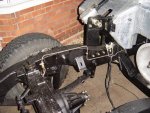
Anyway. The front axle is fitted..finally!
I had a fair amount of setbacks with this one..

People say that you need a 22-25mm spacer between the axle and the spring. Well, is that with or without the mount??? I found out, the hard way, that that is without the mount.

Add 25mm to the 20mm (more or less) thickness of the mount and you get 45mm, I made the mount 50mm. Bad move... After lots of fiddling, measuring, grinding and welding I lowered the front end back on its wheels and......it sat incredibly low. I could only put about 3 fingers between the top of the wheel and the wing.. It sat about 1.5cm from the bumpstops.. Not good!

So, after more ,measuring, swearing, grinding, welding, grinding, measuring, more swearing I made the springmount 25mm high, just like in the back.
Fitted the axle and guess what. The trackrod cleared the springs..just.. But, that's all I needed.
Castor angle is now set at 5degrees. I did this because it lowers the diffnose a bit, the propshaft comes awefully close to my oilfilter. But I've already ordered a smaller one. This one is 140mm tall, the new one only 100mm.
And I don't think the extra 2 degrees of castor angle will do that much.

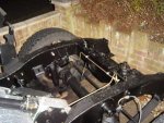
It's looking good. I'm happy. Making the mount less tall raised the front end again. The left side got raised by 2cm compared to before. The other side sits higher. The Landy is leaning to the left, always have done. Must be because of the heavy engine and gearbox that's offside to the left. Plus the tray with 3 batteries on the place of the underseat tank..

Anyway, here's some pics.


PICT0564.jpg


PICT0565.jpg


PICT0569.jpg


PICT0570.jpg


PICT0571.jpg


PICT0572.jpg


PICT0573.jpg


PICT0574.jpg


PICT0576.jpg


PICT0577.jpg
 

Toy-Roverlander

Adventurer
looks like it has plenty of caster.

up travel before the bump stops looks pretty short?


Yup it's got 5 degrees. More than enough..

Up travel is indeed not much. The front end has lifted about 2cm compared to with the old axle and springs. It sits at or just under 2 inches from the bumpstops
Not much I can do here. Either the springs are too soft or the Toyota engine and gearbox is so much heavier...dunno..

Also, the bumpstop on the axle is on an angle and pointing upwards with one point, that doesn't help either.

I might do something about that in the future.
 

Snagger

Explorer
The ride height looks good. To increase the articulation, don't worry about altering the spring seats or shackles, just removve, trim and re-attach the bump stops on the top of the axle tube so that the top face is parallel to the rubber bump stops and their undersides are in direct contact with the axle tube, rather than well spaced away from the axle as they currently are (take a look at the stops on the old axles).

Koos, how high are your spring seats, from spring top to the axle tube at the central point, please? I intend to use 3 degrees castor (standard for SIII and Defender), which should give slightly more track rod clearance for the same size seat, and I think you set your seats just right, by the look of things.

Would you mind photographing the brake lines - I'd like to see how you plumbed in the double hoses, if you don't mind me copying your efforts (immitation being the highest form of flattery and all that...):ylsmoke:.

Well done - enjoy the drive!:wings:
 

Toy-Roverlander

Adventurer
The ride height looks good. To increase the articulation, don't worry about altering the spring seats or shackles, just removve, trim and re-attach the bump stops on the top of the axle tube so that the top face is parallel to the rubber bump stops and their undersides are in direct contact with the axle tube, rather than well spaced away from the axle as they currently are (take a look at the stops on the old axles).

Koos, how high are your spring seats, from spring top to the axle tube at the central point, please? I intend to use 3 degrees castor (standard for SIII and Defender), which should give slightly more track rod clearance for the same size seat, and I think you set your seats just right, by the look of things.

Would you mind photographing the brake lines - I'd like to see how you plumbed in the double hoses, if you don't mind me copying your efforts (immitation being the highest form of flattery and all that...):ylsmoke:.

Well done - enjoy the drive!:wings:

Yup, ride height is not that bad. It does lean forwards though. And it leans to the left, as it has always done...

I haven't altered the bumpstops on the axle yet, I'll do that another time.
I still have to lower the ones in the back.. Too many things to do :)

My springseats are 25mm tall, and with 5degrees castor it gives just enough clearance for the trackrod. So with 3 degrees castor it will be even better.
The one on the diffside is the most difficult one to make due to the strange shape.

You're lucky. I did (nearly) all the brake stuff today. I fitted the new brake pedal with booster and everything, new clutch M/C and most of the brake pipes.

All the plumbing is exactly the same as on a Range Rover. Unlike some people, who do a single line to eacht wheel with a T-piece, I've got dual copper pipes going to each front wheel. So I've got a dual circuit. 2 of the pistons from each front caliper are connected to the rear axle, and the other circuit are the remaining 2 pistons on each front caliper.
I fitted the brake pressure regulator/connecting block to the wing as you can see in the pics.

PICT0580.jpg


PICT0581.jpg


PICT0582.jpg


PICT0586.jpg


PICT0588.jpg


PICT0589.jpg
 

Snagger

Explorer
Great!

I already have a Discovery front axle (identical to a RRC's) and also the brake master cylinder and servo from the same vehicle. I'll be getting a Salisbury rear axle, but that's irrelevant - the brake callipers are the same as on the RR/Discovery axle.

I'm debating whether to use the RR/Discovery brake arrangement like yours, where the large capacity end of the master routes to the rear callipers and one pair of opposing pistons on each front, or to copy the Defender system which has the large side of the master run all the front pistons and the small side run the rear brakes, like on a dual circuit SIII 109 (the system I currently have).

Since the pistons are the same in all the callipers, the capacities of the master will work either way. I may use the defender scheme from the master to brake failure shuttle valve (mounted on the chassis, and slides when there is a pressure differential between front and rear brakes, signifiying a leak, activating a dash warning light).

That shuttle valve has two inlets and thre outlets - one to the rear and two to the front. I currently only use one of the front outlets, the other being blanked - I copied the original piping on my 109 but used all new components, and the single front line runs to a T on the front cross member to run to each front flexible hose and wheel. i could run a second parallel system fromt he redundant failure valve outlet, using a second pair of hoses like you have, rather than having a single line and T's at the swivels to run both halves of the callipers.

One question - what's the cylindrical component with the two pipes in the top attached to the inner wing?
 

Toy-Roverlander

Adventurer
Great!

I already have a Discovery front axle (identical to a RRC's) and also the brake master cylinder and servo from the same vehicle. I'll be getting a Salisbury rear axle, but that's irrelevant - the brake callipers are the same as on the RR/Discovery axle.

I'm debating whether to use the RR/Discovery brake arrangement like yours, where the large capacity end of the master routes to the rear callipers and one pair of opposing pistons on each front, or to copy the Defender system which has the large side of the master run all the front pistons and the small side run the rear brakes, like on a dual circuit SIII 109 (the system I currently have).

Since the pistons are the same in all the callipers, the capacities of the master will work either way. I may use the defender scheme from the master to brake failure shuttle valve (mounted on the chassis, and slides when there is a pressure differential between front and rear brakes, signifiying a leak, activating a dash warning light).

That shuttle valve has two inlets and thre outlets - one to the rear and two to the front. I currently only use one of the front outlets, the other being blanked - I copied the original piping on my 109 but used all new components, and the single front line runs to a T on the front cross member to run to each front flexible hose and wheel. i could run a second parallel system fromt he redundant failure valve outlet, using a second pair of hoses like you have, rather than having a single line and T's at the swivels to run both halves of the callipers.

One question - what's the cylindrical component with the two pipes in the top attached to the inner wing?

What system you use is ofcourse up to you.
Why did you blank off that outlet and have a single line with a T-piece instead of using that outlet for the other wheel cylinder(s) at the front?

That cilindrical thing you mention is the brake pressure regulator/shuttle valve (with electrical connector for dash mounted warning light) and also the rear brakeline connects to this block. What you can't really see in the photo is that there's another brakepipe underneath that cilindrical thing. I reckon it connects 2 seperate chambers inside together or something.
It's a bit of a complicated dual circuit, but it does make sense:coffee:

Basically, the brakepipes go like this:

Master cylinder has 2outlets with dual connections. (see pic)

The 2 rear outlets on the M/C are for 2 pistons at each front caliper

The front outlets:
- 1 goes to a front caliper for the remaining 2 pistons
- other one goes to that block, on the bottom left.

From that block, one outlet the one on the bottom right, goes to the other front caliper.

The one outlet on the rear of that block, with the red plug in it, goes to the rear axle.

This thing regulates pressure to the rear axle. And it has that shuttle valve in it. It's hooked up exactly as it was on the Range Rover. Except that i might have swapped brakepipes going to the left or righ caliper but that doesn't matter.

I like having it like this as I know this is a matched system. It's all designed to work together, albeit on a different vehicle.

Great idea actually to use a Sals axle with discs, much stronger I would say. But it has a 3.54 ratio, what engine do you have? And what diffs are you running at the moment?
 

Snagger

Explorer
I didn't plug the redundant outlet in the shuttle valve - the original was that way from the factory, with a single pipe running to the rear axle and another single pipe to the front cross member. The new valve arrived with a plug in the same port, and since I already had all the original T pieces, I decided dimply to rebuild the brakes to the original schemeatic just using brand new cylinders, copper-nickel pipe and braided hoses.

I'm using a Tdi engine, so it'd pull 3.54 diffs, but I don't want it geraed that high - it's between 35 and 40% higher final gearing than standard and is n ot only non-selectable, but also screws up low range. I have a Roverdrive which raises gearing by 28%, which is a bit less than I'd like for the engine, but it will have to do. I'll be swapping the 4.71 diff from my spare SIII Salisbury axle to the new rear axle before fitting it. A fiddly job, but I have the manuals and an accurate digital vernier, so should cope - I will be building up the new axles before the swap, so the vehicle should only be on stands a short time.

From what you said, it sounds like the small end of your master does one half of each front calliper, while the large end does the other half of the fronts, with the rear brakes plumbed into that large cicuit via that balancing/warning valve. My master looks alittle different, as does the Discovery's differntial pressure valve (I don't have that yet). I don't think the Discovery uses a balancing valve, though - I'll have to take a closer look.
 

Snagger

Explorer
Here are a couple of relevant pictures of the brake system during the rebuild. The pedal box hadn't been fitted yet, but the two master cylinder outlets ran parallel to each other from the master to the failure valve. They cross over on the exit from the valve because the higher capacity end of the master has to be connected to the front brakes. It's neat, simple and original to the 1982 donor vehicle.
 

Attachments

  • brakelinesA500.jpg
    brakelinesA500.jpg
    46.5 KB · Views: 70
  • Jan05-015.jpg
    Jan05-015.jpg
    27.8 KB · Views: 65

JSBriggs

Adventurer
Snagger, It depended on what front calipers you are going to run. The defender and Disco calipers have a single port, while RRC's have a dual port.
Here are a couple manual pages that explain the differences.


Disco
attachment.php


attachment.php


RRC
attachment.php


attachment.php


-Jeff
 

Attachments

  • Disco brakes.jpg
    Disco brakes.jpg
    57.9 KB · Views: 328
  • Disco brakes 1.jpg
    Disco brakes 1.jpg
    97.7 KB · Views: 315
  • RRC brakes.jpg
    RRC brakes.jpg
    36 KB · Views: 323
  • RRC brakes 1.jpg
    RRC brakes 1.jpg
    63.7 KB · Views: 313

Forum statistics

Threads
188,464
Messages
2,905,357
Members
230,428
Latest member
jacob_lashell
Top