Rango.....1942 Willys MB

Metcalf

Expedition Leader
A bit of fun tonight....

100_0951.jpg


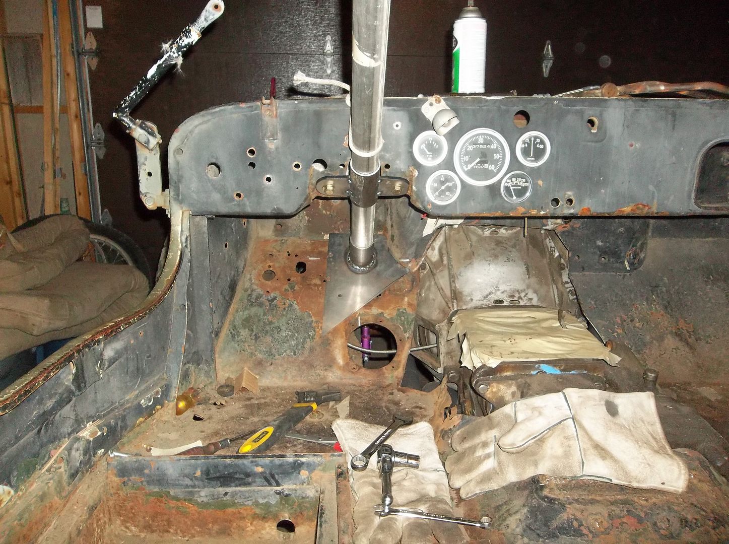
I got the steering column mounts finished up. I still need to stick a few more mounting bolts for the bottom mount.....

100_0952.jpg


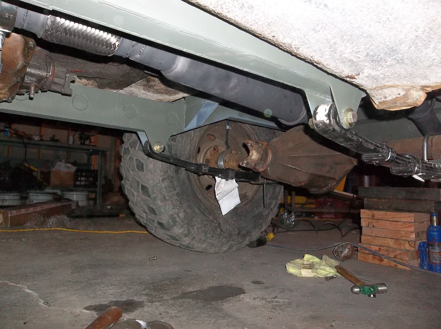
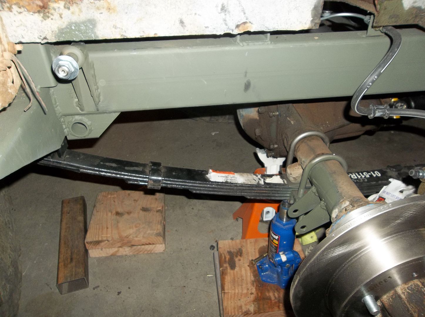
I think I need to trim down my spring pins down a bit. I added 6 degree shims to the rear. Time to stick in the rear driveline tomorrow!

100_0953.jpg


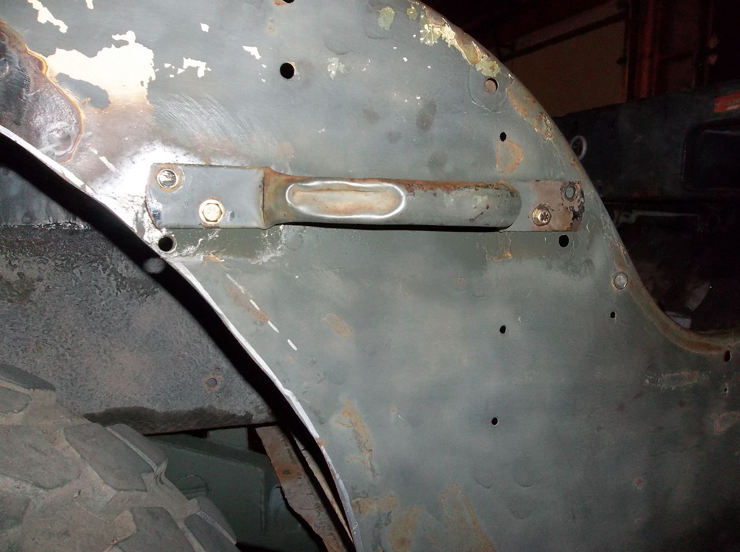
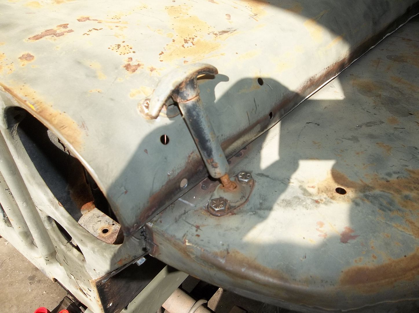
My handle flip idea is going to work well with the larger wheel opening....
 

Metcalf

Expedition Leader
Thanks.

It's coming together pretty neat. Its fun to build something you don't HAVE to drive every day. I still say its basically like a big kids go cart you can drive around on the road......
 

Metcalf

Expedition Leader
Just a few pics...too busy working!

100_0954.jpg


Steering column and steering shaft are in. Tomorrow I might build the drag-link and tie-rod so I can steer!

100_0957.jpg


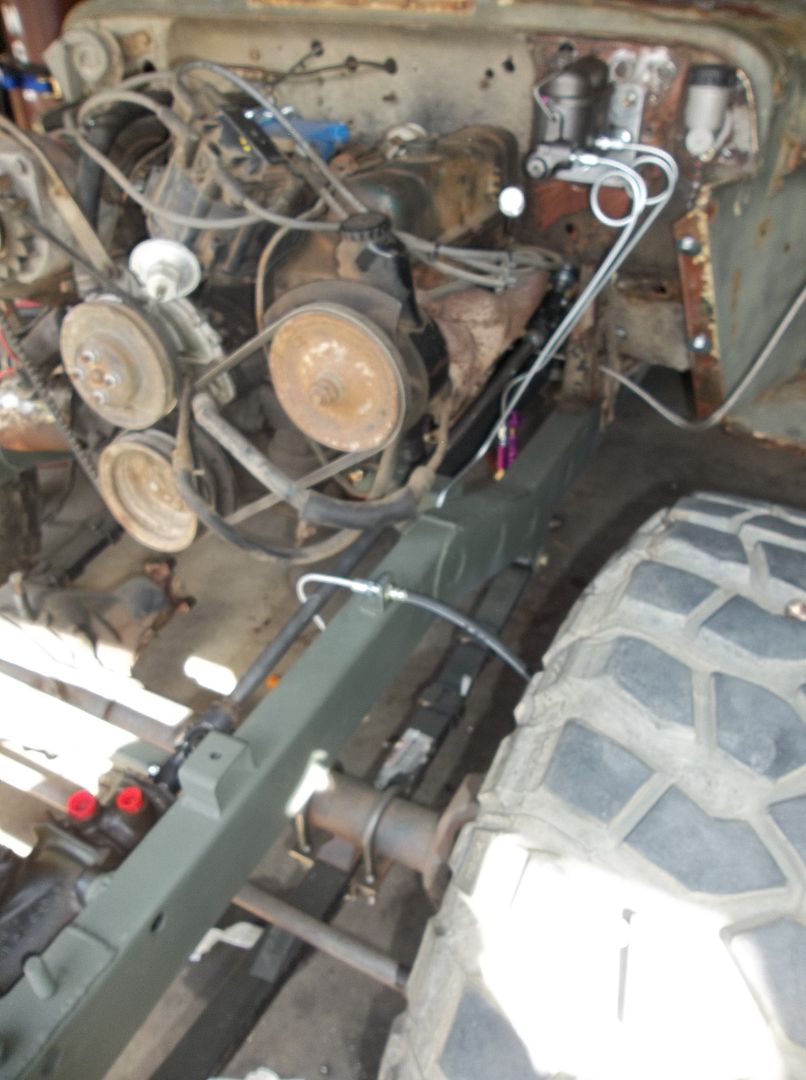
I bolted on the front clip to help plan for the shocks. This this is TIGHT in the engine compartment with the raised fenders! I will have to redo the front brake line to the T-fitting, not a huge deal, but still a pain.

100_0958.jpg


I did a few little things like re-positioning the hood hold downs in the front. Little stuff like this always takes time....

100_0956.jpg


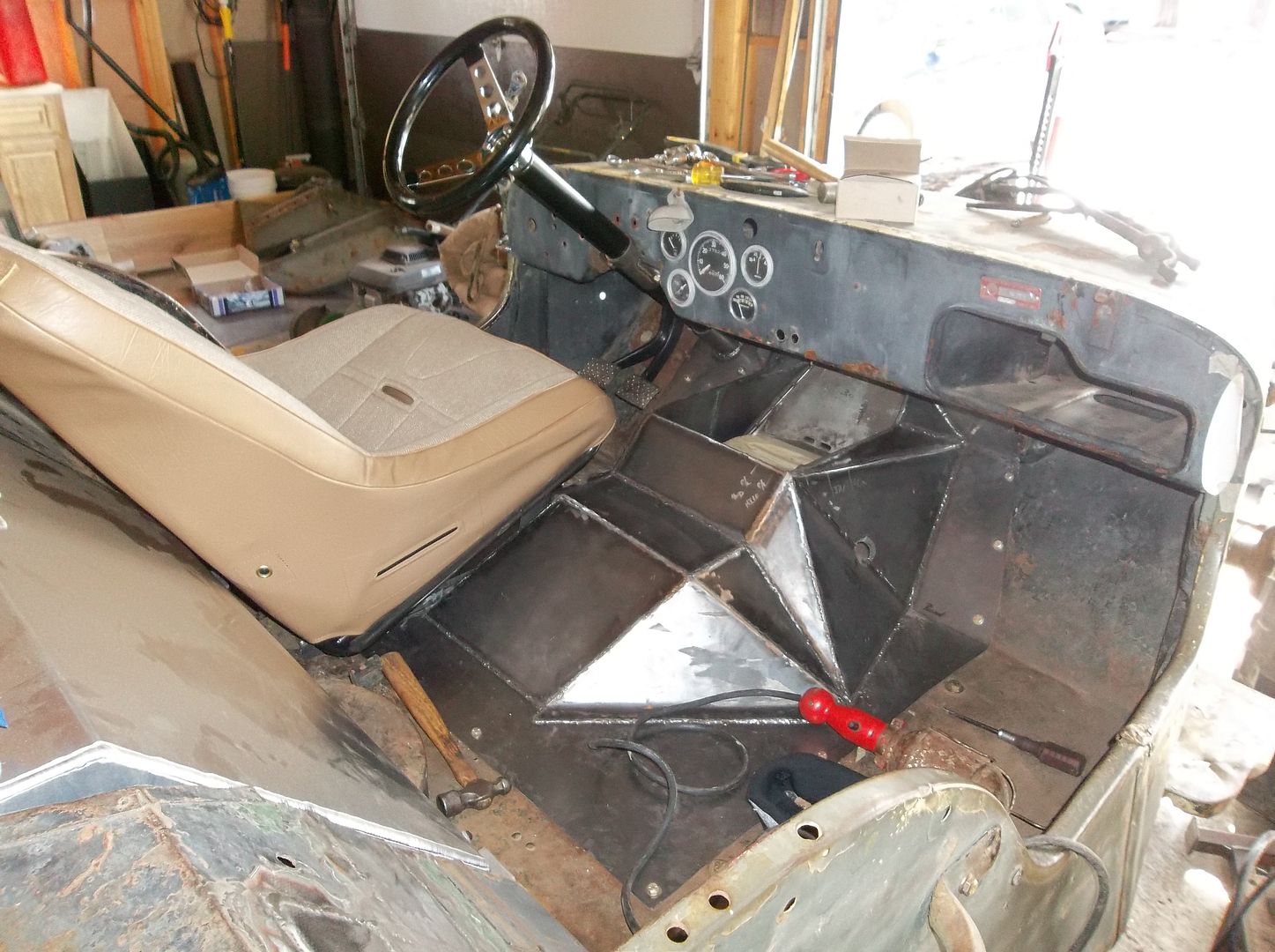
I also bolted in the new tunnel. I still need a top cap where the shifters are going to come out. The drivers seat is also bolted down for the 1st time. The real steering column is in along with the new steering wheel. The steering wheel is WAY to shiny. I am going to have to do something about that. The seating position feels a LOT better than stock. Is it perfect....no. A flat fender body only give you so much space.

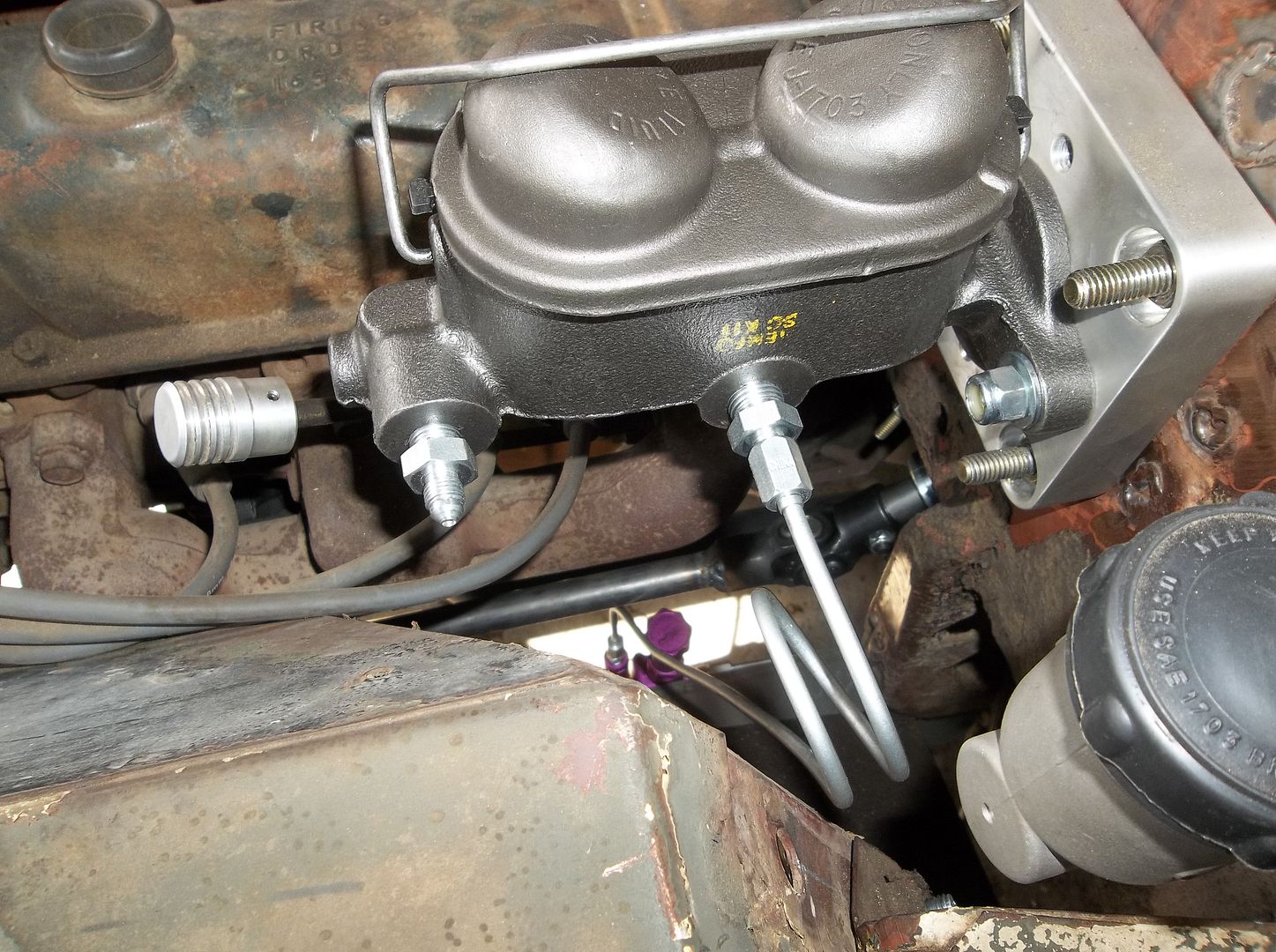
The pedals are all bolted down and the master cylinders connected. The pedals are a little high but not too bad.

I also built some aluminum brackets to hold my electric fan to the radiator but I forgot to take some pics.

More tomorrow.....
 

bishopdunn

Observer
I love your work. I'm getting ready to work on my own 42 MB and will be incorporating several of your ideas. Imitation is the sincerest form of flattery. I'm stretching the seating section 6" to accommodate my 6' 2" 200 lb. frame. Can't wait to see the finished product.
 

Metcalf

Expedition Leader
Today was kinda lame. I got a lot done, but it just didn't go as fast as I wanted.....

100_0959.jpg


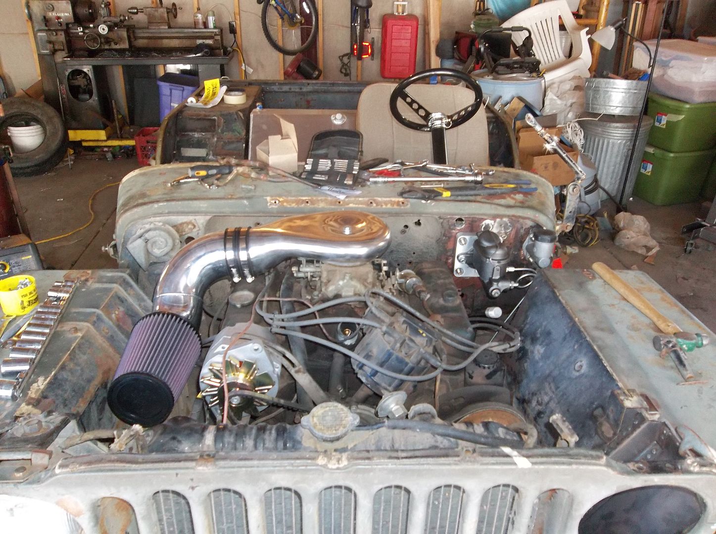
I added some shiny stuff to the engine bay. This was the lowest profile setup I could find for a normal carb. The plenum will have to stick out of the hood about 1-1.5" or so. The hood is going to be trimmed to fit snugly around the plenum and part of the down tube to the air cleaner. It should end up being a fairly clean look when it's done. I didn't really want to cut the hood, but I would rather have the extra room under the belly and oil pan. Things are sure getting tight under the hood. Even with just a V6 and the grill pushed forward 1.38" there still isn't a ton of extra room!

My new 10si alternator (3-wire) also bolted right in place of the old externally regulated unit....nice! I think I will need a belt about 1" longer or so and a a connector plug for the sense and indicator wire.

100_0960.jpg


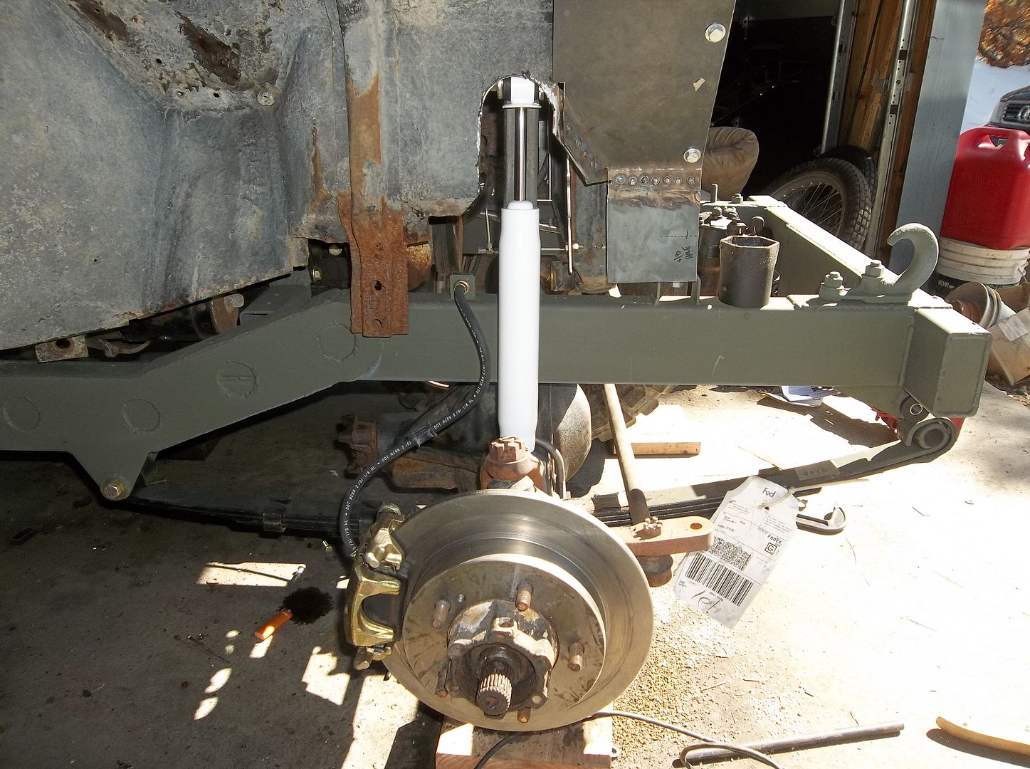
I got a shock mounted.....big whoopy do! I ended up getting a 9.3" travel narrow body shock in there. With only 1" lift spring, the axle pushed forward, the narrow axles, and the big tires.....things are getting tight!

I tried not to totally destroy the inner fender. I was able to retain most of it for almost a 10" stroke shock. The other side will be much the same.

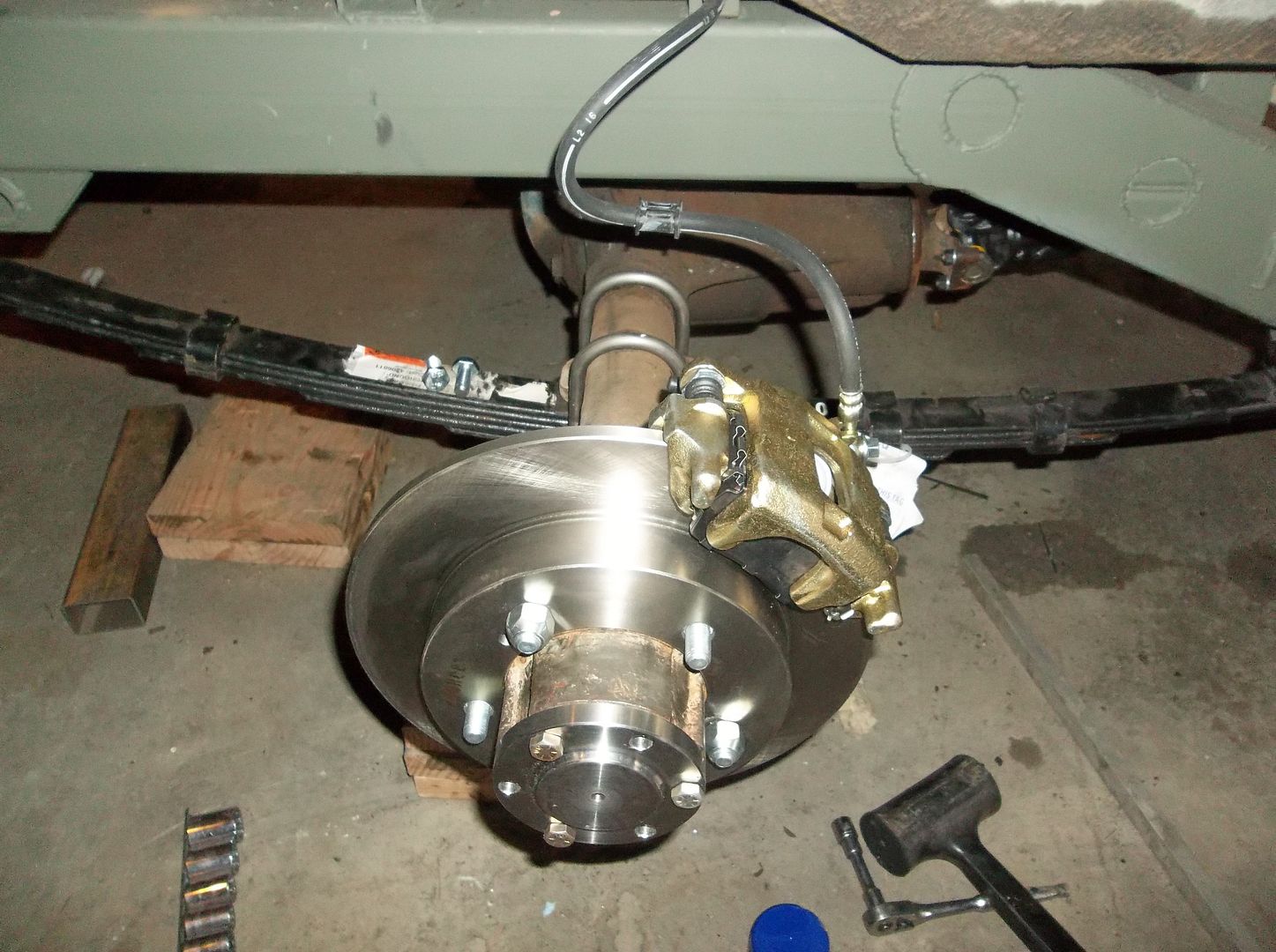
I also got the new waterjet cut brake bracket bolted on. I ended up having to make some .310 thick spacers to get the caliper mount centered over rotor with the .250 thick brackets. That was a little bit off of what my rough math predicted, but oh well. Interesting enough. Once squared up my cheapie saw is able to maintain .003-.005 on a saw cut with the set stop. Making small spacers is pretty easy and doesn't require any lathe time.....

100_0961.jpg


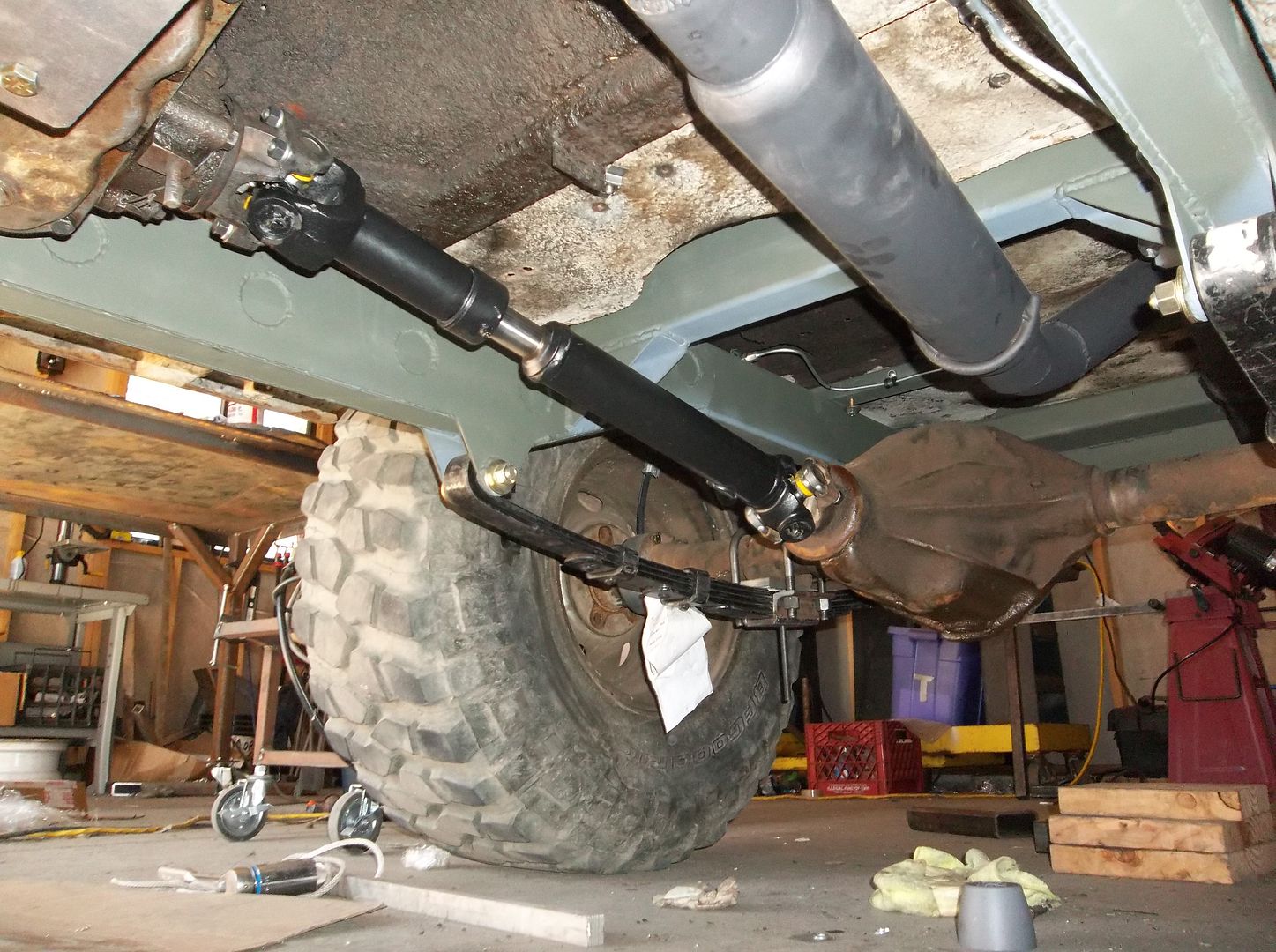
The rear driveshaft fits! I had Tom Woods make up one of there standard 1310 shafts. The angle is just about 11-12 degrees, not great, but it will work for this old thing. The rear driveline is also just about 22" long, not bad for a flat fender!
 

Metcalf

Expedition Leader
I love your work. I'm getting ready to work on my own 42 MB and will be incorporating several of your ideas. Imitation is the sincerest form of flattery. I'm stretching the seating section 6" to accommodate my 6' 2" 200 lb. frame. Can't wait to see the finished product.

No worries, copy away! I wouldn't have posted the build and tried to detail the ideas I had if I didn't want everyone to be driving around in a cool old flat fender!

6" is a big stretch! Even 3" with the proper seat and wheel tub design would make all the difference. If your going to stretch it....its always easy to just add a few more inches!

I don't even know if I can remember all the moving around I did on this thing....and inch here, an inch there. It sure all adds up in the end. This thing is like a real life hot wheels car. Its so out of proportion in a few areas its almost funny. I still giggle a little bit when I look at it now that its rally taking shape.
 

Metcalf

Expedition Leader
Yup, that is basically the reason I kept my super short adapter. The small front driveshaft u-joint thing is a pain, but the long rear driveline is a good trade off. The transmission and transfer case also end up almost ahead of the seats. This makes getting the seats lower a little easier.

If I had to do it all over again I would do a T18 transmission with the short 1" Novak adapter for the D18. This would only be abut 1.5-2" longer than what I have now.

Starting with a totally blank sheet of paper and NOT having a bunch of parts sitting around, I would do a LOT of things different. I used what I had though, this wasn't about building something out of an open catalog with an unlimited budget. This build is an attempt to get people to start BUILDING there vehicles again, not just ordering stuff out of a catalog. Ok....off my soapbox.....
 

Metcalf

Expedition Leader
Tonight was one of those nights. On the one hand it was really cool, on the other hand kinda annoying with the little stuff.

100_0964.jpg


I got one side of the rear axle all converted to the new full float system. I ran into some small issues however.

-The seal didn't fit. The OD of the seal was too larger for my early bearing hub. Honestly I think I am just going to buy two new hubs to get everything to be 100% like it should. I may bore out the bearing hub I have for the newer seal.

Th-e spacing was also a touch different from the front to the rear with the disc brake bracket. I use .310" spacers on the front and .495" spacers on the rear? I still haven't figured that one out. I'm glad I had a small easy to make spacer to get everything centered up. If it would have been just a flat bracket I would have been out of luck. I also had to use some slightly longer M12, 1.25 pitch bolts on the rear caliper mounts.

There was also a radius on the disc brake spindle that was not on the front drum version. I ended up having to chamfer the rear of the ID bore of the brake bracket to clear the radius.

The new full float shaft from dutchman slid right in and bolted up. The bolt pattern and length where spot onto my calculations. I wonder what would be the best kind of bolt to run on the rear floater? I'm thinking maybe a flanged serrated bolt with blue loctite? Studs?

100_0965.jpg


I also built the shock mount on that corner. My new invisible shocks are sweet! I ended up having to run the 10" stroke at about a 45 degree angle to get it to fit with 4" of uptravel or so. Ideal...no. Sometimes you just have to make a compromise for packaging. With it being so freaking low with the 1" springs and not wanting to trim out the wheel tub this was basically the only place for the rear shock to go. I think it will be ok.....I can always change my mind later.
 

MrBeast

Explorer
Yeah the shock being at that angle is going to be a bit odd, and it will only have about 50% of its efficacy.

Why not put the shock behind the axle, and bolt the top of it to a bracket mounted to the bottom side of your roll bar mount?

If you tie your cage into your frame this would be a perfect spot to run it up to.
 

Metcalf

Expedition Leader
Yeah the shock being at that angle is going to be a bit odd, and it will only have about 50% of its efficacy.

Why not put the shock behind the axle, and bolt the top of it to a bracket mounted to the bottom side of your roll bar mount?

If you tie your cage into your frame this would be a perfect spot to run it up to.

With the super light vehicle having the shock work at 50% might not be that bad....

I couldn't get the shock outside the tub with the narrow (54" wide ) rear axle, just not enough room between the tire and the tub.

In a perfect world the wheel tubs would not extend out past the outside of the frame. Then I could stand the shock up anywhere I want. If I was gong to build another tub from scratch I would make the floor only be 29" wide instead of 32.5" wide. I've had my fill of sheet metal mods for now!
 

Forum statistics

Threads
188,293
Messages
2,904,993
Members
229,961
Latest member
bdpkauai
Top