The evolution of "Alpine" Tundra

RoundOut

Explorer
Wiring up the rear bumper accessories

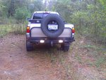
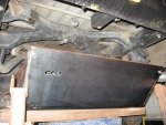
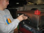
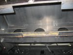
With my new bumper, I have the backup sensors, auxiliary backup lights, license plate light and trailer wiring harness to wire up before calling this project complete. Before leaving for Tulsa this past weekend, my son and I got some of the wiring done for the accessories. For the cleanest install, I wanted to have a single primary wiring harness to fish into the cab. We wired the license plate light, backup sensors, and power wires for the backup lights all in the same dress-up kit.

First, I spliced into the factory license plate light wiring and ran a feed wire toward the passenger side and up the swing-out carrier. Then we started the primary harness from the outer PS backup sensor including the license plate wire (to it's splice in the center of the rear end), the PS auxiliary backup light and the inner PS backup sensor. Zip-tying these, we continued with the DS inner backup sensor, auxiliary backup light and outer backup sensor. As we added wires to the dress-up kit, we wrapped the whole length of harness with electrical tape for extra protection.

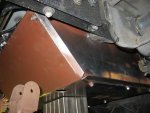
Because the sensors were about 15" apart across the back bumper, their respective plugs on the cicruit board end were spaced that far apart in the harness. In order to be able to fish the harness into the cab, I elected to wrap it in the dress-up kit to the ends. It took four stretched six-foot kits to get the long backup sensor wires all bundled up. After the third kit, I didn't wrap the entire dress-up tubing with electrical tape, because we knew it would be unwrapped for final installation. We just taped one wrap about every six inches.

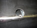
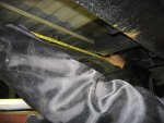
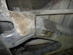
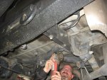
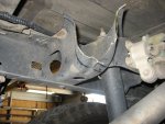
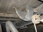
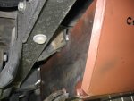
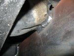
Our final destination for the ends of the harness would be below the console. I originally thought we would enter the cab through the fire-wall up front. We started out zip-tying the harness, following the tail-light harness forward. We got to the point just below the driver's seat, and realized that it continues into the engine bay protected in some heat-resistant tubes. I didn't have any of those, so I started looking for other options. Under the seat and floorboard there were several plugs, but they would not be acceptable because of their position under foot. I found a plug in the back of the cab, about 6" above the floor where the back seat sits, and about 6" in from the side that would do the trick nicely.

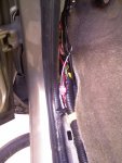
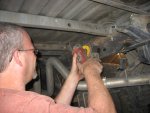
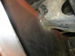
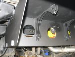
We pulled that plug, cut an 'x' in it, cut about 1.5" off the lower left (as one looks rearward) portion of the plastic trim on the driver's side by the back seat to almost expose the plug (this allowed us to handle it without affecting appearance too much), put the plug around the harness, pushed the harness in the cab, reset the plug, adjusted the harness for best fit with appropriate flexibility, and then put some silicone RTV on the plug, to seal it up. We pulled up the outer edge floor step trim to expose the edge of the carpet and ran the harness forward to the kick panel.

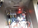
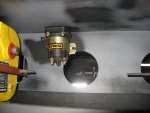
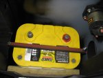
While I had the kick panel off, I took the opportunity to wire up the Ham harness and the two other power cable harnesses I previously ran through the firewall. I put heat shrink female connectors that mated up with the battery terminal adapters that I purchased at West Marine. We pulled apart the end of the dress-up kit housing the bumper accessory wires to allow adding the power harnesses from the firewall accessory power runs. I re-wrapped it and routed it under the steering wheel and over to the console. About four to six feet of extra harness is now stored behind the lower portion of the console until we can finish this install.
 

RoundOut

Explorer
Icom 208H installed - Pics finally!

I tried to have this radio totally hidden, except for the external antenna, which an ordinary thief would assume was for my mic-less CB (the mic detatches), probably. Here are the pics of the Icom install...

1) The sunglasses holder that I swapped in for the garage door opener holder that was there before.
2) The sunglasses holder, modified to allow my remote faceplate to be kept in there.
3) The mic-hanger with the mic hung on it.

The head unit is under my seat. Cables for power, antenna, remote speaker, and remote head run under the carpet toward the door, then in the loom to the kick plate (except the antenna, which goes back to behind the back seat and out the window to the mag-mount on top. From the kick plate, the power goes through the firewall to the battery, the remote head goes up the A-pillar and across the front of the headliner to the sunglass holder, and the external speaker runs to its spot, just above the accelerator pedal.

I looked for a flat spot to mount the mic-hanger, and its present location was as flat as it gets. The tundra has smoothly ungulating curved lines on the whole dash. Note in the third pic, you can see the CB (sort of) behind the Icom mic.
 

Attachments

  • Photo_113007_005.jpg
    Photo_113007_005.jpg
    85.8 KB · Views: 64
  • Photo_113007_006.jpg
    Photo_113007_006.jpg
    57.6 KB · Views: 133
  • Photo_113007_002.jpg
    Photo_113007_002.jpg
    86.9 KB · Views: 99
Last edited:

RoundOut

Explorer
Backup Sensor & Aux Backup lights installed - Pics!

When the bumper was Rhino'd, we still had lots of work left wiring the accessories on it. My son and I ran a harness in wire-loom housing all the wires into the cab behind the back seat, under the carpet along the driver's side edge, up the kick plate, under the steering wheel, and left it coiled under the console until after Thanksgiving this year (2007 for those reading this in the future).

I love learning about electronics, which was my favorite part of model railroading as I built an HO layout in 1/2 of my garage several years ago. These accessories and the Icom install were no different. Lots of fun, sometimes frustrating, but I feel real good about it when you learn something new, have a few opportunities (read: problems) that need solving, and then finally get it working!

To describe the finished part of the harnesses, I'll first describe the backup sensor install...

First, I had to find the wire that is hot when the shift is in reverse. For this, I started by pulling the sill up from the door to expose the primary factory wire loom running to the rear of the truck. Then, I pulled the tail light off, and spotted the red with blue wire that powered the backup lights in the tail light. I looked and looked for that wire and couldn't find it in the factory loom. Then, I noticed the connector right inside the rear fender where the wire changes to red with a black stripe. Back to the front to look for that wire, which was very elusive! I looked twice and couldn't find it, then traced one from the relay, so I knew it was there. I finally found it on the bottom of the loom and tapped it with a 3M connector. I had some 22 gauge aircraft cable left over from my train install, so I took about 5 feet of it to run in the loom to the console area where I planned to put my relay.

I ran the portion of the wiring harness loom that carried the appropriate wires under the steering wheel, and into the console area. After removal of the console, I drilled three 1/2" holes at the rear of the "secret compartment" to allow wires to enter this location. I put grommets in the holes, then fed the (+) & (-) power wires through the left hole, the backup sensor (+) & (-) and hot reverse wire through the middle, and the auxiliary backup light wires through the right. Next, I put insulated bullet connectors and insulated spade connectors in the wires behind the console, so the console can be removed if needed. Before mounting the terminal block, I joined two groups of three terminals to provide multiple locations for mounting wires from similar feed or grounding purposes. After finding and connecting to the right wire, I started work on the location of my fuse bus and aux. backup light/sensor relay & switch. My goal was to have the auxiliary backup lights light up automatically when in Reverse, as well as having the option to turn them on independently to light up the rear behind the vehicle for setting up a campsite, etc. I also wanted the aux. backup lights to not interfere with the backup sensors, such that the switch would also activate the sensors (I got lucky and this was not a problem - yeah!). I bet I spent several hours contemplating the cleanest install layout in the secret console location for this part of the project. I decided to lay out the fuse block on the left side, with the relay and terminal block to the right, respectively.

Finally, I put appropriate connectors on the various wires and connected them as follows:
  • Power feed (+) to fuse block
  • Power feed (-) to ground at front left of secret compartment (this wire is probably totally unnecessary, but if needed, I could convert it to something else later)
  • Hot reverse wire to the relay latching section of the terminal block (front three terminals).
  • Backup sensor (+) wire to the relay latching section of the terminal block.
  • Backup sensor (-) to the ground section of the terminal block (rear three terminals)
  • Terminal block ground section to upper right grounding point.
  • Relay 85 to ground section of terminal block
  • Relay 86 to relay latching section of terminal block (Note that 85 & 86 are marked incorrectly on the white plastic I used to mount this stuff on)
  • Relay 87 to 15A fuse in lower left for power supply to aux lights
  • Relay 30 to backup light (+)
  • Aux. Backup light negative to terminal block ground (this is also unneeded, probably, but could serve as a future accessory wire to the rear if needed.)
  • As mentioned above, I installed an additional switch for the Aux. backup lights. I spliced into the positive feed for the auxiliary backup lights and attached this to the "load" tab of my switch.
  • I attached another 15A fuse circuit to the "power" tab of the switch.
  • I attached another ground lead from the terminal block to the "earth" tab on the switch.
As I have mentioned in previous posts, eventually I'll use different wires (for this temporary switch location) and feed accessories off the fuse block to switches mounted in the lower DIN of my head unit location, after finding an appropriate replacement head unit.

1) Red with black stripe backup light feed wire tapped with 3M connector.
2) Another view of the tapped factory loom from further back.
3) View of fuse bus, relay and terminal block, and (temporary location of) the switch for aux backup lights. Note the red light is lit when the toggle at the front is switched to the right, indicating that my dual batteries are joined full-time.
4) Another view of the fuse bus, etc. with the dual battery switch lit green, indicating that the batteries are only joined when the key is set to accessory or run.
5) Backup sensor display when in reverse with nothing behind. It also has audible tones that beep slowly when nothing is behind, but more rapidly as the vehicle approaches objects. The center of the display has digital distance in feet, too!
6) Auxiliary backup lights on during the day

NOTE: This "secret compartment" is wired MUCH CLEANER than these photos reveal. The wires I used to incorporate the switch for the auxilliary backup lights are way too long for this temporary location. I just wanted to see if it worked easily, or if I needed diodes. Thankfully, the relay and the switch both have integrated diodes, so the backup sensor system does not light up when not in reverse and the aux backup light circuit is closed. When I get the radio head unit swapped out, I'll run switches out of this compartment, up to the switch bank, mentioned above, in the lower DIN location of the radio.
 

Attachments

  • Photo_112707_001.jpg
    Photo_112707_001.jpg
    70.2 KB · Views: 31
  • Photo_112707_002.jpg
    Photo_112707_002.jpg
    105.7 KB · Views: 36
  • Photo_113007_003.jpg
    Photo_113007_003.jpg
    104.7 KB · Views: 66
  • Photo_113007_004.jpg
    Photo_113007_004.jpg
    103.2 KB · Views: 47
  • Photo_113007_001.jpg
    Photo_113007_001.jpg
    69.5 KB · Views: 100
  • Photo_113007_009.jpg
    Photo_113007_009.jpg
    148.6 KB · Views: 102
Last edited:

BrianTN

Adventurer
I haven't read the entire thread so this might have been answered, but why did you put the tire swing out carrier on the bumper? Could you not make a tire swing out carrier replacement for the tailgate and save some weight?
 

pygmyowl

Member
I have a 06 Tundra TRD access cab & was wondering if you were happy with the factory LSD or were ever going to install an ARB rear locker?

Would a high-lift jack on the rear bumper work for changing a rear tire?

Very nice write up & pictures - thanks
 

RoundOut

Explorer
your drinking buddy said:
I haven't read the entire thread so this might have been answered, but why did you put the tire swing out carrier on the bumper? Could you not make a tire swing out carrier replacement for the tailgate and save some weight?

That is so funny that you mention that. I thought of that for the first time this past Thursday, just two days ago. I am not sure why I didn't think of it earlier, probably because I have not seen one done that way before. In addition to lighter, it may have been stronger to have the tailgate frame handle the swingout.

In fact, I could probably dump the tailgate right now. I was talking to DevinSixtySeven today and mentioned your question and he suggested I put some sand ladders back there in place of the tailgate. That makes lots of sense, too.

This may become a project on the to-do list, but for now, I just want to get it dusty and stop having to use a rake to my paint look like I was offroad. Time to put the mods to good use!


.
 
Last edited:

RoundOut

Explorer
pygmyowl said:
I have a 06 Tundra TRD access cab & was wondering if you were happy with the factory LSD or were ever going to install an ARB rear locker?

So far, I have been able to get out of most trouble with the LSD. Not being locked, though, does tend to make me chicken out some, probably saving me lots of money in repairs, too. LOL

I do plan on getting an air locker from ARB, maybe next spring. First I need to finish the battery relocation mod.


pygmyowl said:
Would a high-lift jack on the rear bumper work for changing a rear tire?

Yes, it works great! Slip the nose into one of the D-rings and it stays in there nicely. Much more securely than just sticking it under the bumper!

pygmyowl said:
Very nice write up & pictures - thanks

Thanks! It has been fun seeing a vision finally become reality, albeit piecemeal.


.
 

RoundOut

Explorer
Santa came early...

Earlier this week, my buddy Tom and I went to pick up the replacement backup sensor system from Mark at C.E. Offroad. While there, we were talking about the dual battery relocation and Mark asked if I was putting in an onboard air system concurrent with the battery relocation. I said I would like to mount the tank behind the batteries somehow. He asked if I had a tank yet, to which I replied, "No." He pointed over to a truck project he started and said he'd never finish and said "You can have the one over on that truck if you can take it off."

SCHWEEEEET!

Tom and I got some wrenches and got busy.

After taking a wire brush and flap wheel sander to it, and dropping the brackets in some pool acid (muriatic acid) to get the rust off this morning (and looking like a coal miner from all the black paint dust covering me head to toe), here's what it looks like now...

I'll prime it first, then use some undercoat paint to give it a durable finish for under the bed toward the rear.

Because it had some rust, I am going to have it hydrotested first. I don't want shrapnel popping my new swing-out spare tire!

If all goes well, I'll use it; if not, Oh well.

The drain plug is on the bottom, btw. Kudo's to the guy/gal who sees catches the other problem in this photo (that I have already fixed, but put back for the enjoyment of this puzzle... actually for another reason, but before anyone catches it, the puzzle will have to do).


.
 

Attachments

  • Photo_120107_001.jpg
    Photo_120107_001.jpg
    92.8 KB · Views: 44
Last edited:

RoundOut

Explorer
Painting the 4-gallon tank...

For the record, I wanted to know the tank's volume. I filled it with water and then poured it into a five gallon bucket. It was almost full. I then had a two gallon bucket that I filled about half-way. I poured the water from the half-full, two-gallon bucket into the five gallong bucket, and wallah, it was at the top. So, I guess it is a 4 gallon tank.

Well, I cleaned up the WD-40 I had sprayed on the air tank a few days ago to keep it from rusting, and then used some fine grit sandpaper to prep it for paint. Muriatic acid cleaned the rusty spots from the inside, I rolled it back and forth to get good coverage, rinsed it thoroughly a few times, and then dried it with my heat gun. Then, I used some alcohol on a rag to clean up any dusty stuff and any remaining oily film. Good to go, or so I thought.

I chose some undercoating from the local Ace Hardware. I should have just used primer. The weather yesterday was not cooperative with the undercoat paint. It smelled like crude oil and didn't dry any faster than crude oil. I put the thing on a hanger in the garage and turned on the heater. Finally it started drying.

This morning, I showed my son, and picked it up. Darn if the undercoat didn't just wipe away in a couple spots on the ends. So, I tried to get all the stuff off that was loose and then touched it up. It's still hanging, hopefully this time to dry more solidly. Maybe this stuff just doesn't ever dry.

See my next post, for an explanation of why it won't matter much anyhow. Once I mount it, it will be almost internal...

EDIT:

I painted the inside with some Rustoleum. I bought two little cans (1/2 pints each) of white. I poured them into the tank with a funnel. I put some rubber stoppers in the fittings to keep the paint inside, then rolled it all around to get good coverage. I then drained out the excess, which ended up being a lot more than I expected. There was almost one and half cans recovered. Below are some pics I took of it.

The first pic is pretty lame, but shows the interior of the tank. Not bad, considering it was from my phone. LOL. The second one is of the funnel below the drain hole as the excess paint was draining.


.
 

Attachments

  • Photo_121807_001.jpg
    Photo_121807_001.jpg
    62.2 KB · Views: 41
  • Photo_121807_002.jpg
    Photo_121807_002.jpg
    82.7 KB · Views: 30
Last edited:

RoundOut

Explorer
Battery Relocation Phase I - It finally begins!

Yesterday, I went up to Creative Engineering Offroad, and Mark had finished the fabrication of my under-the-bed battery and air tank box. As usual, his design was quite impressive. We had scoped out a plan and he had come up with an even better solution. We lined up and cut out the X-shaped cross member that held the spare-tire winch, put the box into place, tacked it and finisish-welded it.

I took the nice camera and snapped some decent pics of the first part at CEO. After leaving CEO, I went to my buddies shop and put it up on the lift to prime and paint the new "cross-member". The red primer was what Mark had painted the top before we welded it in place. I bought a can of that to paint the box, as much of the skid plate and some of the sides of the box were already primed. I bought two cans of flat black for a finish coat. I underestimated how much primer and paint I would need by one rattle can each. Luckily, my buddy had some on hand, although the primer was grey. I switched to grey primer for the box part, after finishing the skid plate and inspection port cover with oxide red and a couple coats of flat black each. Unfortunately, I totally ran out of flat black with just a little bit left to paint, right above the batteries.

Here is a description of the pics below:

1) The finished box with the skid plate on (upside down as it will be placed under the bed)
2) The air tank's drain hole as seen through the access port on the skid plate. At FastenAll in The Woodlands, I found a handy hex-head npt bushing to use to drain this with a low-profile. I have seen some pull-string drain cocks, and I am considering working one of those in somehow.
3) The inspection port. Again, upside down. This will be used to adjust the terminals, should one come loose through vibration, without having to remove the whole skid plate.
4) The air tank end (rear end), still upside down on the table.
5) The battery end (forward end). Note several things... the tall nuts welded to the exterior to secure the skid plate, the nuts welded to the interor for the inspection port, The threaded rods and nuts used to apply tension to the battery bracket to hold the battery in place, the two-inch angle iron that the batteries rest on, with a cut-out center place for loading the batteries.
6) The batteries fit perfectly on top of a 2x6 board, used to space the terminals sufficiently high off of the tension bracket. This was a solution that was surprisingly not designed from the outset, but was better than design. I'd rather be lucky than smart! LOL
7) A view without the tank in place - a bit lighter for the mounting process, plus I still had to prime/paint.
8) Aligning the box, under the not-long-for-the-world cross member.
9) Thank God for the sawzall, that hitch receiver is too deep under the bed and it needed shortening. Note to self, next bumper build, use a shorter hitch receiver.

Now comes the more difficult (at least for me) part, which is deciding how to route wires from the engine bay, staying as far as possible from hot exhaust pipes. Toyota has not left much room for these considerations. DevinSixtySeven has advised to come in through the wheelwell between the inner wheelwell and the plastic liner. I have never had that liner off, so this will be a fun learning curve.
 

Attachments

  • IMG_2441.JPG
    IMG_2441.JPG
    763.3 KB · Views: 25
  • IMG_2442.JPG
    IMG_2442.JPG
    734.1 KB · Views: 21
  • IMG_2443.JPG
    IMG_2443.JPG
    565 KB · Views: 23
  • IMG_2444.JPG
    IMG_2444.JPG
    704.2 KB · Views: 28
  • IMG_2445.JPG
    IMG_2445.JPG
    703.1 KB · Views: 33
  • IMG_2447.JPG
    IMG_2447.JPG
    607.1 KB · Views: 32
  • IMG_2452.JPG
    IMG_2452.JPG
    685.5 KB · Views: 29
  • IMG_2449.JPG
    IMG_2449.JPG
    815.6 KB · Views: 27
  • IMG_2448.JPG
    IMG_2448.JPG
    702.6 KB · Views: 27
Last edited:

RoundOut

Explorer
Battery Relocation Phase I - more pics

When we started lining it up, we decided that it would fit best and be most stable if there were "corners" cut in the front two parts of the X-shaped cross member, and clean cuts in the rear.

Here are some addition pics of the install...

1) Measure twice...
2) Cut once.
3) OK, cut twice. (just kidding) We used an angle grinder to cut as much as we could, and finished with a sawzall.
4) The notch in the forward left part of the former cross-member
5) Corresponding notch in the forward right part of the former cross-member
6) Mark using a flap-wheel to make size adjustments and remove paint prior to welding.
7) Drilling pilot holes for the cable routing. This was the first step in punching the holes. What a cool tool Mark had for this... It was a hydrolic punch that would punch up to 10 gauge steel with holes from 1" to 3".
8) Me punching the holes. Note the Blue Seas battery switch on top of the box, and the Taco in fab for some military axles in the background.
9) The holes after punching. The hole punch makes holes for the right size grommets in electrical boxes. It is a $675 tool. Ouch, but it sure works well.
 

Attachments

  • IMG_2453.JPG
    IMG_2453.JPG
    629.1 KB · Views: 23
  • IMG_2455.JPG
    IMG_2455.JPG
    754.3 KB · Views: 26
  • IMG_2456.JPG
    IMG_2456.JPG
    630.3 KB · Views: 27
  • IMG_2460.JPG
    IMG_2460.JPG
    653.9 KB · Views: 26
  • IMG_2461.JPG
    IMG_2461.JPG
    561.9 KB · Views: 22
  • IMG_2462.JPG
    IMG_2462.JPG
    511.8 KB · Views: 27
  • IMG_2466.JPG
    IMG_2466.JPG
    560 KB · Views: 29
  • IMG_2464.JPG
    IMG_2464.JPG
    511.2 KB · Views: 34
  • IMG_2463.JPG
    IMG_2463.JPG
    564.9 KB · Views: 28
Last edited:

RoundOut

Explorer
Battery Relocation Phase I - more pics - final welding

More pics from the install at CEO...

1) Tack weld on back right of the remaining part of the cross-member. In this picture, the spring hangers look very close to the box. Not so, in fact we made sure that there was plenty of clearance in case we wanted to replace the springs in the future and had to remove the spring hanger bolt.
2) Tack weld on left side
3) Finished welds on right side - nice bead, for welding upside down!
4) Left side finished.
5) View in place without the skid plate, from the rear
6) View in place without skid plate, from the front

When finished at CEO, as I mentioned before, I headed to my buddies shop to prime and paint the box. I have to finish this up with just a couple shots of flat black, and then begin the wiring.
 

Attachments

  • IMG_2467.JPG
    IMG_2467.JPG
    615.3 KB · Views: 25
  • IMG_2469.JPG
    IMG_2469.JPG
    566.5 KB · Views: 21
  • IMG_2470.JPG
    IMG_2470.JPG
    450.6 KB · Views: 20
  • IMG_2474.JPG
    IMG_2474.JPG
    593.4 KB · Views: 18
  • IMG_2473.JPG
    IMG_2473.JPG
    574.4 KB · Views: 19
  • IMG_2472.JPG
    IMG_2472.JPG
    503.9 KB · Views: 19
Last edited:

RoundOut

Explorer
Battery Relocation Phase II - To Do List

Initially, I had purchased two runs of 2 gauge red cable and one run of 2/0 gauge black. After getting the box installed, it dawned on me, that I don't need to have both runs of red if I relocate the solenoid from the dual battery controller to a location closer to the batteries. I need to return the 2 gauge red cables and get a run of 2/0 red. I might even save some money after this swap! There is plenty of room in the box for the solenoid, so that will be at the top of the list. At this time, I also need to properly plumb up the air tank. So, here is the to-do list that relates to wrapping up this install...
  1. Locate and mount the dual battery solenoid DONE 1/10/08
  2. Locate and mount the battery switches in and/or near the battery box. Changed plan. Will locate a keyed primary lockout on the 2/0 positive lead in the OEM spot (Done 1/23/08), and an auxiliary lockout switch on the negative lead in the box next to the solenoid.
  3. Re-route the control wiring for the dual battery solenoid. Done 1/18/08
  4. Fit grommets into the wiring holes of the box. Done 1/18/08
  5. Route the primary wiring from the box to the original battery location DONE 1/11/08
  6. Route the air line from the compressor to the tank. Done 1/18/08
  7. Mount my Blue Sea fuse blocks (without the fuses) which I am going to use as high-current terminal blocks, to secure original wiring up front. These will go on the fender near the original battery location. Done 1/18/08
  8. Mount my Viair 400C compressor where the original battery is. Done 1/23/08.
  9. Route the compressor intake line over near the K&N intake (colder air point) Done.
  10. Route the interior pressure gauge line through the firewall and locate pressure gauge with as close to a factory appearance as possible - I think I will be swapping out my head unit and mounting this in a lower DIN, if it fits. If not, it will go on an A-Pillar gauge pod. In fact, the more I think of it, it will have to go on the A-Pillar. There just won't be enough room for a 2-5/16" gauge in the lower DIN of the factory radio location. Done 8/3/08.
  11. Locate and install a winch power port in the rear. Done 7/14/08.
  12. Extend the lead wires on the winch by about 2 feet, allowing it to reach the front power port and planned location of the rear power port. Changed. Instead, I shortened the leads and made an extension cord to connect the power outlets to the winch. The extension cord can also act as a jumper cable extension cord. Done 7/14/08.
  13. Locate and install quick-release air fittings at the front and rear and plumb them up to the manifolds. Done 7/14/08.
Hopefully, I can get this done in the next couple weeks.


.
 
Last edited:

RoundOut

Explorer
Battery Relocation Phase II - Solenoid

This morning after driving to the office, I noticed a vibration coming from the battery box. I thought the left tail pipe was pretty close to the forward left, lower corner, and indeed it was making noise at idle. I'm headed up to Mark's in the morning to have him adjust the routing of that side of the exhaust, a quick fix.

Also, an afternoon trip to O'Reilly's yielded a significant savings on cable. I returned the two runs of 2 gauge red and ordered a second 2/0 black (they didn't have red for a week+). The net savings was enough to get me another heat gun to replace the one I burned up this past weekend (defrosting the freezer - LOL), some heat shrink tubing, and some terminal lugs. It'll be here in the morning.

This afternoon I pulled the heavy gauge wiring from the dual battery system previously installed in the engine compartment, including the solenoid, returned the OEM fuse/relay box to its original mounting points, and tied up the dual battery control harness until I can get more time to re-route it. On a trip to Home Depot, I picked up some grommets for the cable holes on the front of the box (turned out to be the wrong size - I thought the holes were 1", but they were 7/8"), some mounting hardware for the solenoid, and some weather stripping for the air tank to prevent abrasion on the tank from the mounts.

I determined that the solenoid will fit in the location shown below and still allow the batteries to be removed for replacement or inspection as needed without removal of the solenoid. I love that it will only require a short cable run (less than a foot) to each battery! This shortens the 9-10' trip that the cable had in the front and cleans up the front compartment significantly.

I chose a high location for the solenoid to limit water intrusion, but in case fording a stream allows water into this space, I will be sealing the seams of the solenoid with RTV before mounting any cables to it.

Pics below:
  1. Close-up view of solenoid as seen from the inspection port. I still need to paint here, this is where I ran out of flat black just before being finished. Argh.
  2. View of the auxiliary battery in position with the solenoid just a few inches away, and a good view of the battery mounting bracket. It still needs a coat of flat black, too.
  3. View of solenoid mounting position from the air-tank side of the box. Also note the brackets for the air tank.
 

Attachments

  • IMG_2478.JPG
    IMG_2478.JPG
    544 KB · Views: 29
  • IMG_2477.JPG
    IMG_2477.JPG
    482.9 KB · Views: 21
  • IMG_2476.JPG
    IMG_2476.JPG
    484.6 KB · Views: 24
Last edited:

Forum statistics

Threads
189,056
Messages
2,912,490
Members
231,545
Latest member
JPT4648
Top