Since there has been some question about the installation instructions (not included) I thought I’d write a quick how-to in case anybody was worried. It really is pretty self-explanatory for the most part.
The kit has 4 spacers, 2 larger in diameter than the others. You can’t install them wrong as they only fit one way – the larger ones go on the back while the smaller on the front. You’ll see a hole that aligns with the air fitting so you know you’ve clocked them correctly, otherwise they simply wouldn’t go on at all.
I’ll skip all the safety speech here about proper lifting of your vehicle and assume you know what you’re doing if you’ve decided to take this on. Not responsible for your death or dismemberment if you do something stupid, yada yada yada.
I chose to actually fully remove the struts when doing the job but you don’t have to pull the rears completely.
Before removing the struts you’ll want to bleed the air off in the system. I did it using a GAP IId tool. Any of the diagnostic computers should be able to do it, or If you don’t have one you can start by having the truck in access height to vent as much air as possible, then you’ll have to be careful when removing the air lines (see below)
For each corner the process is the same. Remove the strut by undoing the 3 15mm nuts at the top.
(a moment’s pause here to suggest you get yourself a ratcheting 15mm box end wrench – trust me, you’ll be glad you have it as although you can do the job with a standard wrench it’s much easier with a ratcheting wrench)
Don’t bother undoing the air line; instead use a sharp razor knife to cut the plastic just above the ‘bubble’ in the line, which is just above the brass fitting. Make a clean, straight cut. If you didn’t use a computer tool to relieve the air pressure, be very careful here and go slowly, only cutting enough to let the pressure bleed off. Once the air is out, you can complete the cut. If you get carried away and cut the line fully while it’s under pressure you likely won’t damage anything but at the least you’ll be in for a shock when it blows off. There’s a lot of pressure in the system, so again be careful here.
Use a jack to support the bottom of the strut then remove the large single bolt that secures it to the lower control arm and lower the jack to lower the strut then remove it.
With the strut freed, use a 12mm wrench to remove the brass air fitting. You’ll be re-using this in a moment. Gently pull the compression ring off the plastic airline then remove the hex portion. Re-install these on the supplied black airline as they were on the original, and screw this back into the strut. Remember-this is brass so don’t get carried away on the torque. On the other end of the supplied black airline you’ll find a quick-connect coupler. To remove these you push the collar in while pulling the line out. To install, simply push the line in until it seats home. I actually found the supplied lines a bit longer than needed and trimmed each between ½ and 1” depending on which corner I was working on.
Now install the spacer to the top of the strut. Feed the short black airline up through the provided hole in the spacer and use the original 3 15mm nuts to secure it. On the rear, you’ll need to place the strut back loosely in place prior to bolting on the spacer. On the front you can do it outside the vehicle then put the strut back in place.
With the spacer installed, re-install the strut. Use the jack to lift the bottom of the strut while you guide it home at the top, being careful to fit the black plastic air line up through the original hole and not pinch it against the mount. Start the supplied 15mm nuts to hold the strut in place but don’t tighten yet. Now push the end bare end of the stock air line into the supplied quick connect until it seats home. In the future, should you have to remove a strut this will be easier to undo than the taking apart the stock brass fitting.
(A word about the supplied nuts – they have small crimps in the threads to act as locks, this makes them difficult to tighten. A squirt of WD40 or similar on the stud threads prior to installing the nuts will make things a bit easier)
On the front strut, fit the shorter of the supplied limit straps to the rear-most mounting stud on the spacer (this is why you didn’t tighten the mounting nuts in the previous step). On the rear strut, fit the longer limit strap to the forward-most stud. Now you can tighten all three nuts and fit the large lower bolt. You may need to use a pry bar along with your jack to persuade the lower end of the strut to line up.
On the front strut, fit the loose end of the limit strap to the sway bar end link on the upper control arm using the stock nut to capture the bracket. On the rear, attach the limit strap to the upper bolt on the sway bar end link at the sway bar itself. (this is a bit of a pita, but you’re pretty much done at this point)
Double check that everything is secured and the limit straps aren’t binding on anything and put the wheels back on – you’re good to go!
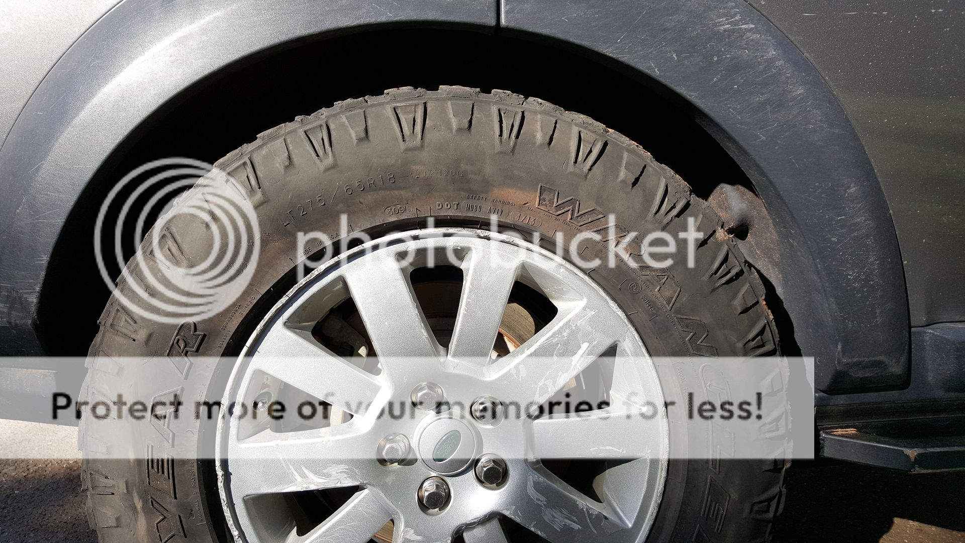
With my tuck sitting on the bump stops I measured 17.75” from wheel center to the bottom of the wheel arch at the rear and 18.75” at the front. I didn’t bother measuring from the ground to the wheel arch or over-all height as that will vary based on the tires you are running, but you can use that number to calculate your own truck’s new minimum height. There is plenty of clearance in the wheel wells now for my current 275-65-18 Duratracs when on the stops. As soon as they arrive at my local store, I’ll be fitting 275-70-18 Cooper STT Pros which are listed at 33.31” diameter. Though I may need to do some extra trimming here and there, the extensions should still keep the tires out of the wheel wells in a failure.
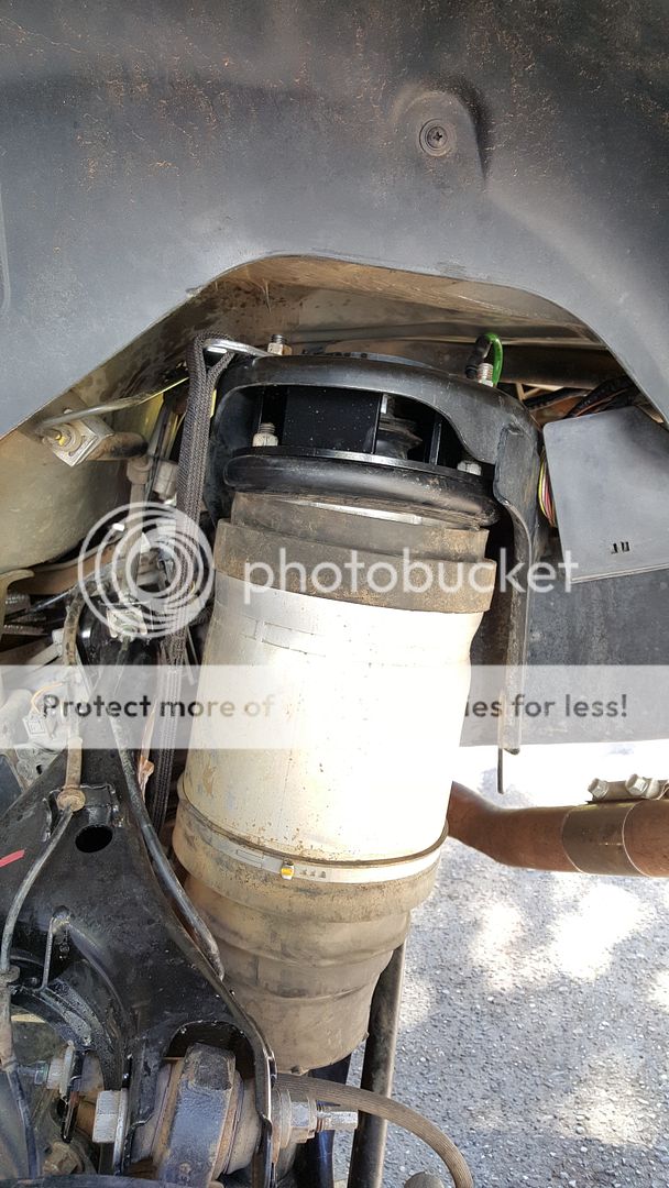
Front spacer installed:


Rear spacer installed:
Front wheel clearance on the bumpstops:
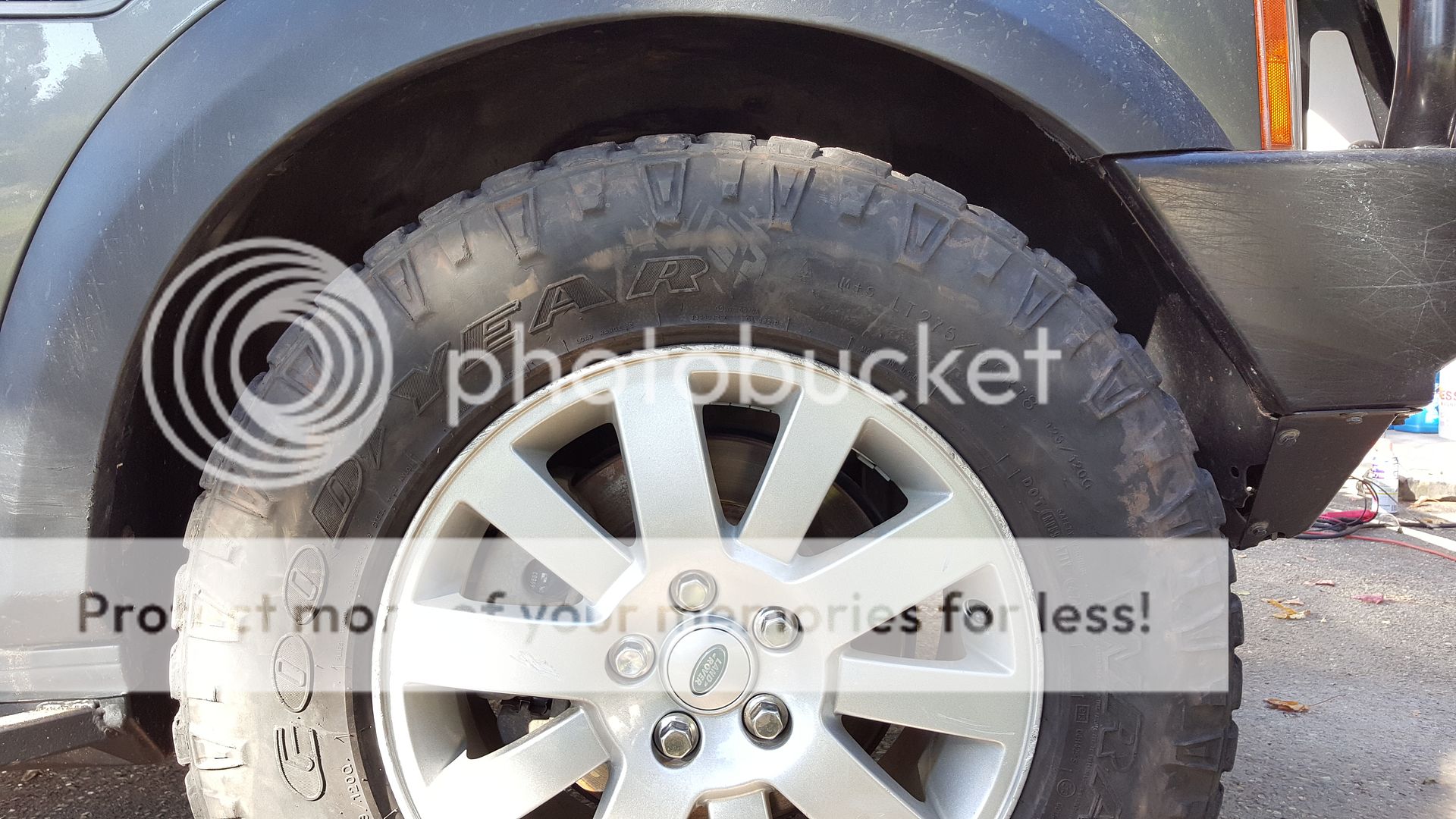
Rear wheel clearance on the bumpstops:
Over-all view on the bumpstops:


