ramblinChet
Well-known member
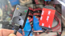
The Noctua NA-FC1 is a compact controller designed for 4-pin PWM fans, enabling manual speed adjustment. By turning the NA-FC1’s speed control dial, users can set a PWM duty cycle from 0% to 100%. When the INKBIRD ITC-1000 Temperature Controller detects excessive heat inside the K470, it signals the NA-FC1 to activate both fans at the pre-set speed. This system is experimental, and I plan to test it under various conditions to determine the optimal fan speed settings.
The NA-FC1 controller is compact, measuring approximately 1.5 inches in length, and lacks mounting holes or tabs. To secure it, I used 3M VHB (Very High Bond) 5952 tape, which can support up to 80 pounds per square inch in static shear. For this application, I considered the dynamic load and applied a safety factor of approximately 4:1, meaning one square inch of tape can reliably hold a 15–20-pound object.
To track expenses for this project, I am documenting all purchases. These include the 3M VHB 5952 tape, a 21mm hole saw used to cut an opening for the Sealcon cable gland (referenced in my previous post), a 67mm hole saw, and several 1/0 AWG lugs and ring terminals.

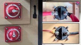
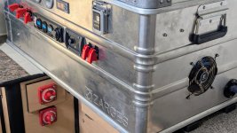
I used the 67mm hole saw to drill a precise hole in the battery box beneath the K470 case for mounting a Blue Sea Systems Manual Battery Switch. This switch allows me to isolate the battery bank from other electronics during maintenance or emergencies. Drilling this hole was challenging because I was enlarging an existing hole, leaving no material to guide the pilot bit.
The accompanying image illustrates how I addressed this challenge: I used a scrap piece of wood as a backer to guide the pilot drill. After identifying the center of the existing hole and drilling alignment holes, I attached the backer, drilled a pilot hole to guide the hole saw, and created a perfectly centered hole in the battery box.

After drilling the hole, I test-fitted the battery switch and planned the placement of its four mounting holes. The 67mm hole, as specified by Blue Sea Systems, left a 1mm gap around the switch. To center it precisely, I folded two strips of thin cardboard and inserted them evenly around the switch’s circumference, acting as flexible spacers to ensure perfect alignment.

Additional expenses include socket head bolts and screws for mounting the battery switch. I also purchased two extra screws to prepare for installing the Victron Energy BMV-712 Battery Monitor shunt in the battery box.

The Ancor Premium Battery Cable Stripper (703075) is designed to strip cables from 8 to 4/0 AWG, making it essential for this project. Its adjustable head optimizes blade depth for cutting through insulation, and a lever rotates the blade 90 degrees to remove the insulation efficiently in one motion.

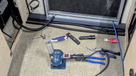
For this project, I chose the Ancor 8 to 1/0 AWG Hex Lug Crimper, which has consistently produced reliable crimps. Measuring 15.4 inches, it fits easily in my tool bag, making it highly portable. Ancor offers a larger crimper for 8 to 4/0 AWG, but at 24.4 inches, it was unnecessary, as my calculations confirmed that 1/0 AWG wire meets the project’s requirements. The accompanying images show a precise crimp and finished wires with heat shrink tubing. I used Ancor marine-grade wire, tinned copper lugs, and adhesive-lined heat shrink tubing to ensure durability. My goal is to build a safe, cost-effective system, as substandard connections between premium components create vulnerabilities, much like weak links in a chain.

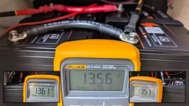
Balancing a new battery bank before use is essential for optimal performance, longevity, and safety. Batteries should have identical voltage and capacity, ideally from the same manufacturer and batch. To balance them, follow these steps: First, fully charge each battery and let it rest for several hours, disconnected from chargers or loads. Next, use a multimeter to verify that the open-circuit voltages are within 0.1V of each other. Then, connect the batteries in parallel using cables of identical length and gauge to ensure equal resistance and current sharing. Allow the connected batteries to rest for 12–24 hours, then integrate them into the system and charge them once more before use. The accompanying images show the open-circuit voltages for each battery before connection.
For this project, I repurposed a 6–7-year-old Victron Energy BMV-712 Smart Battery Monitor previously used in my Jeep. I cleaned areas with corrosion, circled in red in the accompanying images, using a Dremel and abrasive bit to eliminate resistance in the battery bank’s main circuit. The BMV-712 provides real-time monitoring of battery state of charge, voltage, current, and energy consumption via its built-in Bluetooth and VictronConnect app, enabling optimized battery usage and protection against over-discharging.
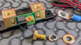
To mount the BMV-712 on a ¾-inch-thick exterior wall, I aimed to maximize screw depth without penetrating the outer surface. I measured carefully, selected appropriate screws, and prepared to drill pilot holes to the optimal depth. Since I needed only two holes and had #10 flat washers available, I fashioned an adjustable drill depth gauge to ensure precision. One of the best things about working for yourself is you get to call the shots and go your own way...

The NA-FC1 controller is compact, measuring approximately 1.5 inches in length, and lacks mounting holes or tabs. To secure it, I used 3M VHB (Very High Bond) 5952 tape, which can support up to 80 pounds per square inch in static shear. For this application, I considered the dynamic load and applied a safety factor of approximately 4:1, meaning one square inch of tape can reliably hold a 15–20-pound object.

To track expenses for this project, I am documenting all purchases. These include the 3M VHB 5952 tape, a 21mm hole saw used to cut an opening for the Sealcon cable gland (referenced in my previous post), a 67mm hole saw, and several 1/0 AWG lugs and ring terminals.

I used the 67mm hole saw to drill a precise hole in the battery box beneath the K470 case for mounting a Blue Sea Systems Manual Battery Switch. This switch allows me to isolate the battery bank from other electronics during maintenance or emergencies. Drilling this hole was challenging because I was enlarging an existing hole, leaving no material to guide the pilot bit.
The accompanying image illustrates how I addressed this challenge: I used a scrap piece of wood as a backer to guide the pilot drill. After identifying the center of the existing hole and drilling alignment holes, I attached the backer, drilled a pilot hole to guide the hole saw, and created a perfectly centered hole in the battery box.

After drilling the hole, I test-fitted the battery switch and planned the placement of its four mounting holes. The 67mm hole, as specified by Blue Sea Systems, left a 1mm gap around the switch. To center it precisely, I folded two strips of thin cardboard and inserted them evenly around the switch’s circumference, acting as flexible spacers to ensure perfect alignment.

Additional expenses include socket head bolts and screws for mounting the battery switch. I also purchased two extra screws to prepare for installing the Victron Energy BMV-712 Battery Monitor shunt in the battery box.

The Ancor Premium Battery Cable Stripper (703075) is designed to strip cables from 8 to 4/0 AWG, making it essential for this project. Its adjustable head optimizes blade depth for cutting through insulation, and a lever rotates the blade 90 degrees to remove the insulation efficiently in one motion.

For this project, I chose the Ancor 8 to 1/0 AWG Hex Lug Crimper, which has consistently produced reliable crimps. Measuring 15.4 inches, it fits easily in my tool bag, making it highly portable. Ancor offers a larger crimper for 8 to 4/0 AWG, but at 24.4 inches, it was unnecessary, as my calculations confirmed that 1/0 AWG wire meets the project’s requirements. The accompanying images show a precise crimp and finished wires with heat shrink tubing. I used Ancor marine-grade wire, tinned copper lugs, and adhesive-lined heat shrink tubing to ensure durability. My goal is to build a safe, cost-effective system, as substandard connections between premium components create vulnerabilities, much like weak links in a chain.

Balancing a new battery bank before use is essential for optimal performance, longevity, and safety. Batteries should have identical voltage and capacity, ideally from the same manufacturer and batch. To balance them, follow these steps: First, fully charge each battery and let it rest for several hours, disconnected from chargers or loads. Next, use a multimeter to verify that the open-circuit voltages are within 0.1V of each other. Then, connect the batteries in parallel using cables of identical length and gauge to ensure equal resistance and current sharing. Allow the connected batteries to rest for 12–24 hours, then integrate them into the system and charge them once more before use. The accompanying images show the open-circuit voltages for each battery before connection.

For this project, I repurposed a 6–7-year-old Victron Energy BMV-712 Smart Battery Monitor previously used in my Jeep. I cleaned areas with corrosion, circled in red in the accompanying images, using a Dremel and abrasive bit to eliminate resistance in the battery bank’s main circuit. The BMV-712 provides real-time monitoring of battery state of charge, voltage, current, and energy consumption via its built-in Bluetooth and VictronConnect app, enabling optimized battery usage and protection against over-discharging.

To mount the BMV-712 on a ¾-inch-thick exterior wall, I aimed to maximize screw depth without penetrating the outer surface. I measured carefully, selected appropriate screws, and prepared to drill pilot holes to the optimal depth. Since I needed only two holes and had #10 flat washers available, I fashioned an adjustable drill depth gauge to ensure precision. One of the best things about working for yourself is you get to call the shots and go your own way...


