2021 RAM 3500 Tradesman | AEV Prospector | FWC Grandby

ramblinChet

Well-known member
My research indicates that failure of the A-pillar Molding in RAM trucks is not uncommon. Mine began to progressively fail months ago and it became so loose and weak that I stopped using it since my greatest concern would be one day having it fail and leaving me flat on the ground with a potential injury. After removing the A-pillar molding that was only marginally useful I recognized the design failure and hoped this has been corrected. BTW - that white rolled up fabric on the left side is an airbag.
RC 25-102.jpg

Once I began using the Google to poke around the interweb I discovered both the original Mopar part (#6NF75TX7AD) and a revision (#7KF73TX7AA), were available. Based upon the new part number I suspected a significant revision had taken place so I took a chance and ordered the possibly updated part. Below you can see the original part up top while the revised part is below. The inset picture within the original part displays a common failure point while the inset within the revised part shows the reinforcement in the same area. It will be interesting to see if this new variant permanently corrects the issue or not.
RC 25-103.jpg

Here is my beautiful new A-pillar Molding installed. While preparing to place my order I checked pricing from a half-dozen parts suppliers and saved 25% with ten minutes of effort. Interestingly, the price for the actual part was less at all other sites except one, but shipping was 150-200% higher at all others.
  • $50.14 + $09.84 = $59.98 (moparonlineparts)
  • $45.20 + $15.99 = $61.19 (worldpartsdirect)
  • $47.68 + $15.35 = $63.03 (moparpartsonsale)
  • $47.88 + $18.92 = $66.80 (tascaparts)
  • $48.90 + $19.55 = $68.45 (mymoparparts)
  • $68.50 + $12.01 = $80.51 (mopar)
Shading my interior is a Cover Craft UVS100 Premier Series Custom Sunscreen that I have enjoyed for the past 1.5 years. After another year or so I will provide a full report although at this point I have used it enough times that I am happy I spent the money.
RC 25-104.jpg

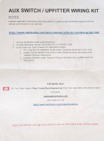
Now that I have the Baja Designs backup lights installed in the AEV rear bumper, it was time to wire everything up. I briefly considered ordering the pre-configured wiring harness directly from AEV but since I already had the supplies and the harness alone was $185, I decided to build my own. On the left you can see the Ancor 16 AWG marine grade tinned copper wire (red and black) that would be used. On the right you see the Mopar Aux Switch Upfitter Wiring Kit (#68398184AB) that came with my truck. If you have the auxiliary switches there is important information contained within this kit so attached to this post you will find JPGs of the information for reference purposes.

Down at the bottom you will see a roll of Tesa Triple A 51036 flag-resistant PET cloth tape which "provides excellent abrasion protection of automotive harnesses and withstands high temperatures and demanding environmental conditions." The tape is wrapped over top of black Electriduct 1/4" Flame Retardant Wire Loom Tubing Polypropylene Split Corrugated Conduit (5.5mm ID) that surrounds the Ancor wiring. "This polypropylene wire loom is used to protect and organize wire harnesses, harness assemblies, loose cable bundles, and is ideal for automotive and industrial applications." The roll of PP conduit was 100' so I did not include it in this picture.
RC 25-105.jpg

Some of the Ancor products I used for building this wiring harness - on the left is an Ancor Heat Shrink Terminals & Connector Kit (#320101) and on the right is Ancor Heat Shrink Tubing Kit (#330101). Tool used include Ancor Single Crimp Ratchet Tool (#703010), Wire & Cable Cutter (#703005), Klein heavy-duty wire strippers (#K12035), Bosch 15-amp professional heat gun, and others. Of course, you can spend less money and maybe the items you receive are fine. For my purposes, by default I usually search for the best within reason. for electrical components this is especially true and ultimately I consider it the price you must pay for some additional safety. The last event I am interested in experiencing is a fire inside my camper while sleeping alone miles away from any help. It just isn't worth it to me so the few extra dollars and attention to detail are well worth it.
RC 25-106.jpg

With the harness complete I was excited to see the lights finally come to life. Whomever at AEV came up with the idea of including integrated lights as part of the rear bumper deserves a firm handshake and pat on the back. The inset picture up top simply shows an Ancor heat shrink connector properly installed. Note the proper crimp ratchet tool did not damage any of the heat shrink and the adhesive inside the heat shrink was heated up to a temperature where the bonding agent began to weep from the ends signifying proper application. The inset on the bottom depicts the same wire from the Mopar Aux Switch Upfitter Wiring Kit attached to Ancor 16 AWG wire, encased in Electriduct, heatshrink applied, and waiting to be wrapped with Tesa cloth tape.

Note - the two wires off to the left are 40' extensions connecting my house battery to my solar panels sitting out in the sunlight in front.
RC 25-107.jpg

Of course I ventured out at night to test the newly installed rear bumper lights and was happy with their performance. Unfortunately, I was unable to manually control the digital aperture, shutter speed, and ISO on the camera inside my phone so you must keep in mind the images you see are not as accurate as real life. In short, if the scene appears dark the phone exposes for a longer period to make it lighter, and vice-versa.

The top row is looking out the drivers window at the side mirror and seeing what is behind the truck. On the left is a picture taken with only the OEM black-up lights mounted in the LED tail lights. These do a good job but are nothing compared to the picture on the upper right which includes the AEV/Baja Designs rear bumper lights. The bottom row represents the same scenario when viewing my OEM back up camera through my dash mounted Uconnect 8.4". That unit attempts to do the same as the camera by increasing the exposure on dimly lit scenes while underexposing scenes that are well lit. I am happy with the performance and only wish I would have had these installed when my AEV Prospector was built years ago.
RC 25-109.jpg

And finally, a tip of the hat to the fine folks at LockNLube for selling the proper brass coupling the connect their LockNFlate locking air chuck to my Milton 500 series inflator gauge. The white residue you see around the fittings is LOCTITE 565 which is a "general purpose thread sealant for an instant low-pressure seal." Once again, it only costs a few dollars more and takes a few extra minutes. I'm worth it and so are you...

...tryna make ends meet, you're a slave to money then you die...

RC 25-110.jpg
 

Attachments

  • Aux Switch Upfitter Wiring Kit 002.jpg
    Aux Switch Upfitter Wiring Kit 002.jpg
    190.8 KB · Views: 3
  • Aux Switch Upfitter Wiring Kit 001.jpg
    Aux Switch Upfitter Wiring Kit 001.jpg
    147.9 KB · Views: 3
Last edited:

Pzary3233

New member
I LOVE your thread and enjoy seeing the updates! We almost crossed paths in the Ozarks we ended up running the OOAT and again in Mississippi.

I am looking at building one of these trucks in a slightly different configuration. I am having a hard time justifying the 6.4L which is the powertrain I want especially with the 8 speed. What are you seeing your fuel economy looking like these days? How about your "comfortable" range? Do you find that the range is limiting for your adventures or do you find that it is adequate for back country travel? We are going to spend a lot of time in the North Maine Woods and range is going to be a big limitation I feel.
 

nckwltn

Explorer
I LOVE your thread and enjoy seeing the updates! We almost crossed paths in the Ozarks we ended up running the OOAT and again in Mississippi.

I am looking at building one of these trucks in a slightly different configuration. I am having a hard time justifying the 6.4L which is the powertrain I want especially with the 8 speed. What are you seeing your fuel economy looking like these days? How about your "comfortable" range? Do you find that the range is limiting for your adventures or do you find that it is adequate for back country travel? We are going to spend a lot of time in the North Maine Woods and range is going to be a big limitation I feel.

I have a very similar setup, albeit a 2015 Prospector (4 door) and Hawk. I live out west where you can travel back-country tracks that have no fuel stops for a couple hundred miles without some significant re-routing, and range anxiety is something that came up on my last trip out in the Mojave. On day 3 we changed up the route, which put the fuel station at the end of the last day. I did make it with my 5 extra gallons, but I was concerned (although, I don't think my low fuel light came on... so I had dozens of miles of range remaining).

If I'm spending a lot of time in 4-low on the trail, I'm going to be in the high single digits for MPG (7-9), but out west we do have a lot of elevation gains. Cruising down the freeway at 65-70 I'm getting just a hair over 12 MPG. Its only a few MPG difference between on/off road, but over ~31 gallons in the tank, it does add up.

In attempts to stick inside stated/rated payload capacities the Hemi was the way to go for me. It mostly came down to weight. I liked the off-road articulation that the 2500 suspension offered. The Cummins cuts 1k of payload because it's SO heavy. As a result, if you have a 2500 Cummins, your payload is something like ~1500-1700lbs (at least in the 4th gen Ram HDs). I didn't intend to be towing anything so didn't need that extra torque the diesel offered either. In addition the extra up-front cost of the Cummins was also a factor. I calculated it was going to take me 7+ years before the extra expense of the 6.7 would pay for itself in estimated fuel savings. If you're full time on the road, diesel might yield a fuel savings much sooner.

Now, what I didn't consider is that I'm pretty much stuck with the factory 31 gallon tank; there are California compliant aftermarket diesel tanks that will give you in the 50 gallon capacity. My buddy with a 3500 and his 50 gallon tank usually fills up at the start of a 5 day trip, and doesn't need to touch a fuel station again until he is on his way home. Whereas I'm filling up at the beginning. With an extra 5 gallons in a fuel bladder for emergency, and I still need to fill up half way through a 5 day trip (assuming we are moving camp every day). I'm sure his on-highway fuel economy is +2-4 mpg what I get and his trail economy might even be better than that.

I'm super happy with the setup. Wish I could mount the 37" tire in the factory location, and I wish I could swap larger fuel tank, but a couple of jerry cans/fuel bladders work for now.

IMHO, I'd rather have a smaller truck, with a more simple setup (GFC style), but the Hawk makes things easier for me and more comfortable for my wife and 2 young daughters when they come along.
 

ramblinChet

Well-known member
I LOVE your thread and enjoy seeing the updates! We almost crossed paths in the Ozarks we ended up running the OOAT and again in Mississippi.

I am looking at building one of these trucks in a slightly different configuration. I am having a hard time justifying the 6.4L which is the powertrain I want especially with the 8 speed. What are you seeing your fuel economy looking like these days? How about your "comfortable" range? Do you find that the range is limiting for your adventures or do you find that it is adequate for back country travel? We are going to spend a lot of time in the North Maine Woods and range is going to be a big limitation I feel.

My overall average fuel economy is 12.3 MPG over the past 90k miles and to support what @nckwltn shared, I sometimes see 15-16 mpg on the highway at 100 km/h while most time on the trail I see 8-10 mpg for slow trails and 10-12 mpg for average ones.

When I plan a trail I treat it much like a mission so calculating how much water, fuel, food, etc. is perfectly normal. One habit I have is to always begin the trail with a full bag of gas along with plans to refuel. My plans normally involve exploring small towns just off the trail within 20-30 miles of either side - I highlight these stations with a special symbol on my navigation software knowing that I will most likely stop at on or more. When I am on the trail and I burn down to one-half tank remaining I begin looking ahead and if there is a station just off the trail I jump off and gas up. If I burn down to only one-quarter of a tank remaining my mission immediately changes to locating fuel.

Keep in mind this is in addition to having two five-gallon Jerry cans available as emergency reserve. My plan seems to work well and there has not been a single time where I have been required to tap into my emergency reserve fuel. Decades ago I spent time flying in the military and fuel was an important calculation and consideration for every single mission - I treat it the same today. To me part of the enjoyment in overlanding centers around solving these logistical issues such as water, fuel, and food, on a regular basis - I consider it constant exercise.

I respect that your challenges in the forests of northern Maine may require additional considerations since there may not be small towns with fuel available. Make sure to document your adventures and share them with us so we can all learn from your experiences. Maybe in a year or two my plans are to return to that area of these United States. Happy trails!
 

ramblinChet

Well-known member
My Diode Dynamics SS3 SAE White Max LED Pods with Combo beam patterns, serving as A-pillar lights, required replacement since the exterior coating had faded and even began to separate in areas. This confused me since I had other Diode Dynamics installed at the same time and they all appeared to be fine despite being exposed to the same conditions. The inset picture on the lower-right is the MWR Auto-Hobby Shop at the Coast Guard Training Center here in Yorktown - I visit here sometimes when working on my vehicle. The shop has a full selection of Snap-On tools, three vehicle lifts, several open bays, a tire changing machine, etc.
RC 25-111.jpg

For reference - here is the warranty claim submitted through Diode Dynamics. All it took was a simple phone call, a few minutes talking with a young professional at their headquarters in St. Louis, and him confirming that years ago they had a few bad batches of product produced that later showed signs of coating failure, and I was supplied with a warranty repair number. I mailed my lights in and days later new ones were mailed back to me. All the premium lighting manufacturers such as Baja Designs, Diode Dynamics, Rigid, have great products with a great warranty.
RC 25-112.jpg

Here's another shot taken on another day of the Auto-Hobby Shop on base. This time I was going to begin swapping my AEV/Bilstein 5100 series shock absorbers for AEV/Bilstein XP8100 Remote Reservoir shocks. When I was discussing the original build configuration with AEV in 2021 they hinted that the 8100s were possibly going to be available in a year or so but I wanted to run the 5100s for a few years anyway and then swap over so I could measure the difference, if any, based upon my experience. This simple swap turned out to be a bit more challenging than expected although in the end, everything turned out just fine.
RC 25-113.jpg

Here are shots of the rear shocks going in which I predicted were going to be more difficult when compared to the fronts due to the fact that the factory spare tire had been removed and replaced with a larger Titan 30-gallon Spare Tire Auxiliary Fuel System. After spending time laying under my truck and examining the relationship between the conventional 5100s and considering how the 8100s with a piggy-back reservoir would fit - I was concerned with the shock contacting the Titan tank while the axle articulated. Despite my concerns, there are no issues and everything fits well. Whew!

The inset picture up top shows the 5100 preparing to be removed - you can see the tank just off to the left and then bulging out down to the lower-left. Maybe I worry too much but my argument is, I would rather identify and resolve a potential problem on my own schedule instead of being forced to deal with it on the side of a trail, without any warning. Spending a few more minutes during installation can potentially save hours of grief down the road. The inset picture on the lower-right depicts the bottom of an 8100 about to be snugged down and then torqued to 110 pound-feet. Also, make sure to use Anti-Seize Lubricant during reassembly.
RC 25-114.jpg

Harbor Freight was my solution for being in a pinch and requiring a 4-1/2" angle grinder and grinding wheel for five minutes worth of work. Thirty-five years ago I purchase a premium angle grinder and up until maybe five years ago, I still owned it and used it on occasion. But as I grow older I use certain tools less frequently and give them to my son or others who can make better use of them. In this case, the simplest and best solution was under $20 and only a few minutes away. My logic was that if it lasted for this job, that is all I needed. The tool worked perfectly fine and I feel it was the best solution available for my particular scenario.
RC 25-115.jpg

I'm big on reading, and re-reading, and days later re-reading a few more times any sort of instruction that comes with a product. In this case the AEV instructions that came with the 8100s suggested that there may be excess welds on the front spring/shock towers that require grinding down prior to installing the brackets for the remote reservoirs. Thanks to AEV and their detailed instructions, none of this was a surprise when I test fitted the brackets so a few minutes of grinding and my problem was solved. Their instructions also mention to inspect the lower shock bracket where it is welded to the front axle to verify a full weld has been applied. Once again, this is great information to have available and represents a few additional minutes of work now compared to possibly experiencing an unexpected component failure in a random location.
RC 25-116.jpg

The front shocks gave me more of a headache than expected since the nuts and threaded shafts up top on both sides were rusted. Honestly, the rust is my fault - what would have prevented it was immediate application of a lanolin-based brand of corrosion preventive and lubricant. Now you clearly can see when just a few weeks ago I purchased a six-pack of Blaster Surface Shield and am planning to finally spray the underside prior to departing for my next year worth of adventures.

The red-circle shows the offending nut and threaded shaft up top that rewarded me with hours of excitement. This one was on the drivers side adjacent to the anti-lock brake system and associated lines and although the picture suggests there is ample room to stick fingers or a wrench in there, it is really a poor design and there should have been additional access provided. On the passenger side there was a massive amount of room so I reached in with an air cut-off tool and zipped the rusted nut right off.

The inset picture on the bottom right shows how the drivers side was addressed. In summary, I did not want to risk damaging the ABS system so I decided to work from below and cut through the shock shaft where a metal collar sits atop a machined shoulder of the shaft. If you cut the shaft below this point everything up top is still fixed in place. If you cut at the collar, everything in the bushing pack comes apart as soon as you cut through.
RC 25-117.jpg

I finished late into the evening just as the Auto-Hobby Shop was shutting down on base so here is a picture of those beautiful AEV/Bilstein XP8100 Remote Reservoir shocks installed. Over the years I have viewed other RAMs with King or Fox shocks (which are great shocks) installed and the mounting the remote reservoir has always appeared like an afterthought; I have seen them bolted to the plastic wheel well liner, a generic clamp, etc. Attention to detail and professional design in accordance with SAE engineering standards is where American Expedition Vehicles stands out head-and-shoulders above all others. AEV produces OEM quality components that are designed, tested, produced to SAE and FMVSS standards, and are currently being installed on OEM production lines. It's disappointing to say that AEV stands alone and I do hope to see other companies step up to the plate some day - competition is good for the consumer.
RC 25-118.jpg

Some of my buddies are sending daily pictures of them on the trail and asking when I will be joining them. The beautiful blue Power Wagon is owned by Paul (IG: overland_the_horizons). Recently Paul swapped his Palomino camper for a loaded Four Wheel Camper and he could not be happier. Paul summed it up by saying the Palomino was great for weekend excursions but just was not able to hold up for full time use since everything was slowly breaking down.

I met Paul (inset picture far left) while camping three years ago in the Ocala National Forest in Florida and we have shared several trails since then. Matt (inset picture far right) and I met at Overland Expo East two years ago and we nearly crossed paths last fall in the Pacific North West. Since Matt was exploring Florida, I introduced him to Paul who was nearby and as I am complete with my upgrades and maintenance, we are planning to head west together. I think Paul and I both agree that it's strange what desire will make foolish people do... ;)
RC 25-119.jpg
(photo credits to Paul)
 
Last edited:

ramblinChet

Well-known member
Shifting gears here and working to resolve an issue that has been on my mind for quite some time - falling. A study published in the American Journal of Preventive Medicine found that 97.3% of ladder-related injuries occur in non-occupational settings (e.g., homes, farms, or recreational areas) and according to the CDC, over 300 people die annually from ladder falls, and more than 164,000 ladder-related injuries are treated in emergency rooms each year.
RC 25-121.jpg

For an older man like me, the data underscores that age-related factors (balance, reflexes) amplify the risk of even minor falls. A 2-foot drop from a step stool into a camper might seem trivial, but it could lead to a hip fracture or head injury, especially on hard desert ground or rocky forest terrain. The rear AEV bumper provides a 5" x 30" step which is unusual in size but fine for occasional use. Since I climb in and out of my camper a dozen or more times daily I really needed to discover a better solution. These pictures show the step being test fitted and as of now I am still working to resolve how I will permanently attach it.
RC 25-122.jpg

It's time to get down to the details and besides a manufacturers web site, sometimes you find additional details on the product packaging. In this case I was interested in what their recommendation was for lug and wire size regarding the primary positive and negative connection. On this card they specify a #10-32 stud that will accept 4-6 AWG wire and the block itself is designed to handle a maximum of 100 amps up to 32 volts. With this information I made plans to order the somewhat odd sized Ancor 4 AWG #10 lug and since I already have 4 AWG wire, cutter, and crimper, I will be all set.
RC 25-123.jpg

During June of last year I began to consider different layouts for my soon-to-be-upgraded electrical system. Many nights were spend moving scaled digital representations of the pieces around an appropriately sized digital blank canvas which represented the rear wall of my camper on the drivers side. I thought long and hard about this installation and even considered building a false wall out of non-flammable material a few inches out so I could mount all the components on the outside while running all wiring behind.

Here are just a few iterations of my design process which clearly shows that once you begin, many pieces of the puzzle are moved, and provided you take your time and make a sincere effort, the end result will be much better when compared to those initial ones. As you scan Versions 3, 10, 14, and 19, you can see how many different locations of components were conflicting with one another and how some pieces were being brought into the equation while others were being taken out.
RC 25-124.jpg

I was not happy with the direction things were going in the above-mentioned iterations so I took time off and worked on other tasks. In July of last year I dove back in and now considered expanding the area of installation from just the back wall (left of the vertical black line) to also include a small section of the adjacent drivers side (right of the vertical black line). This provided much more flexibility and freedom and involved using a space that was not being used for anything else.

But I still was not happy with my overall design so I set it aside once again.
RC 25-125.jpg

Skip ahead to the past several months, one day I decided to venture into an entirely new direction. This had much to do with a friend who was burned over 60% of his body while sleeping in his camper. A fire broke out and not only did he lose his camper and truck, but he also lost his dog. This convinced me to think about what others had been doing with regards to camper electrical systems and how I could increase the safety of the system.

Here is my first attempt at physically placing some of the components inside a Zarges K470 case where I am planning to mount them. The MPPT 100/30 and Orion XS are leaned up against the wall since I am tentatively planning to install them on this inside wall. Using the inside of the K470 provides much more space, provides additional protection for the components and wires, and also decreases the probability and intensity of a fire. These are all small steps in the correct direction although cumulatively, they will result in a much better system overall.
RC 25-126.jpg

My Victron Energy Lynx Power In (M10) will be housing a series of MEGA fuses. Here is one more example of taking a few extra minutes to perform research and make the correct selection regarding support parts. Fuses are fuses right? Well, Littelfuse is the original designer and patent holder of the MEGA fuse. Other quality manufactures of MEGA fuses include companies such as Eaton (Cooper Bussmann), and MTA (Modular Components).

Other manufacturers vary in quality, materials, or certification depending on the source. They could use inferior metals or lack proper interrupt ratings (e.g., Littelfuse’s 2000A @ 32VDC vs. a generic’s untested capacity), risking circuit failure or fire. Reputable manufacturers provide fuses meeting UL, ISO, or SAE standards. For safety's sake, spending $5-15 per fuse compared to $1-3 for a generic or mislabled brand, is well worth it to me. If you have not guessed it yet, I dive deep into details and you should too.
RC 25-127.jpg

While reviewing my options for connecting all of the components inside my electrical system I began to run into an issue: the Lynx Power In has four connections for components whereas I require five, or possibly six, depending upon how I decide to wire. After mulling it over and cosndiering other options, which I ultimately considered shortcuts, I opted to purchase an additional Lynx Power In and connect it to the existing one.
RC 25-128.jpg

In a previous post we had discussed my initial design considerations related to how I will lay out the gauges and controls on the face of my Zarges K470 premium aluminum case which houses all of my electrical components for my system. I have though about it some more and reorganized things a bit. If you recall my goal was to take advantage of the prioritization of efficiency, logical grouping, and accessibility contained within aircraft cockpit design.

In keeping with that thought process, the BMV-712 takes priority over the MPPT Control since the battery is the heart of my system. The BMV-712’s State of Charge and Time to Go are the most actionable metrics for managing limited energy reserves, especially since solar charging is weather-dependent. The BMV-712 directly informs me of my strategy - when to cut loads, when to recharge, and how much capacity remains. The MPPT Control’s solar data (e.g., Solar Panel Power (W), Charge Current (A)) is crucial for optimizing my primary charging source, but it’s also secondary to knowing the battery’s state.

The INKBIRD ITC-1000 slots in at #3 because it addresses a practical concern in my off-grid setup: component reliability under thermal stress. Victron components are robust but sensitive to heat - he Orion XS and MPPT controllers can reduce output or shut down if ambient temps exceed safe thresholds (typically 50-60°C per Victron manuals). The temperature of the area where the components are housed is important regarding performance of the equipment but is more of a layer of insurance rather than a primary survival metric.
RC 25-129.jpg
 

Kingsize24

Well-known member
Chet, we had the same thoughts as you with the steps. I'm not sure your plans, but there are TONS of options with TorkLift GlowStep Stow N' Go scissor steps. They have some that even sit inside the door threshold and fold inside your camper with the door shut. They have a glow on them for stepping on them at night. We use it on both our slide in, and trailer. They have been amazing. Might be worth a look so you aren't having to find for a place to carry one more thing.

Bigfoot_steps_IMG_4716.jpgGlowStepRevolution_Uprising_Storage.jpg
 

ramblinChet

Well-known member
Chet, we had the same thoughts as you with the steps. I'm not sure your plans, but there are TONS of options with TorkLift GlowStep Stow N' Go scissor steps. They have some that even sit inside the door threshold and fold inside your camper with the door shut. They have a glow on them for stepping on them at night. We use it on both our slide in, and trailer. They have been amazing. Might be worth a look so you aren't having to find for a place to carry one more thing.

View attachment 875513View attachment 875514

Thanks for the tip and pictures. Two other guys I know have those steps and love them and despite them being a popular option for many, they just didn't feel solid and wide enough for me. I purchased the aluminum step-stand around 1.5 years ago and absolutely love it - I use it to enter and exit, as well unlatch all six latches holding my FWC top down. It's 24" wide so I rotate it 90 degrees and it slips right in my back door.
 

Kingsize24

Well-known member
Thanks for the tip and pictures. Two other guys I know have those steps and love them and despite them being a popular option for many, they just didn't feel solid and wide enough for me. I purchased the aluminum step-stand around 1.5 years ago and absolutely love it - I use it to enter and exit, as well unlatch all six latches holding my FWC top down. It's 24" wide so I rotate it 90 degrees and it slips right in my back door.

That's perfect. It DEFINITELY makes a big difference having a stable way to get into your camper. I'm glad you have something that works well.
 

ramblinChet

Well-known member
It's funny how different people handle similar situations. When I was younger and I was tasked with something, I would do it to the best of my ability, but I was never quite happy with the end result. Whatever it was, it worked, seemed fine, and most folks were happy, but inside I knew it could be done better. It was a few years later when I stopped to think, most everything has been done previously by experts in their respective fields, and they have all published information regarding standards and best practices.

Fast forward and now when I am preparing to layout gauges and controls for an electrical system in my camper, I am referencing Department of Defense Design Criteria Standard (MIL-STD-1472H) and a similar publication produced by the Federal Aviation Administration. Some may consider this excessive but to me it's perfectly normal. The layout of instruments, gauges, and controls in a cockpit of a helicopter, or tank, or passenger jet, all share common characteristics such as safety, efficiency, and error prevention.

My goal with this design is to have the most valuable information readily available at a glance and when I want to change the status of something, I desire the layout to be logical, intuitive, and to ultimately reduce the probability of making an error. I attempted to attached the above-mentioned publications but they were too large.
RC 25-130.jpg

At this point it becomes important to begin preparing a final layout that includes measurements. In additional to making some adjustments to the alignment you might have also noticed the grouping of the two pair of switches. Using cues from cockpit layout for aircraft and spacecreaft, grouping switches and instrumentation in clusters provides many advantages such as accessibility and speed, intuitive operation, reduction in human error, etc. Whenever I am involved in design of a system, one of my primary goals includes organization (controls in this case) in a way that aligns with how the operator thinks and works, reducing cognitive load and minimizing error. This is extremely important when experiencing stress such as during an emergency.

I grouped the two switches on the left side since they will both be controlling lights. The first switch is for interior lights and will be the first one encountered when entering the camper and it will be used frequently. The second switch controls the exterior LED lights on the back of my camper and will only be used when setting up camp after dark - but it still deals with lights.

The second pair are grouped because they will be used to turn on or off power to an electrical component (inverter) or to a subsystem (Blue Sea fuse block). I will only be using the inverter for a few hours here and there so I do not want it running, or even in standby mode, when not being used - the switch will manually turn it on when I need it. The final switch will control a Victron Energy Smart Battery Protect that is able to decouple the Blue Sea fuse block from everything else. I don't plan on using this unless I am parking my vehicle for an extended time (weeks or months) and wish to eliminate any and all parasitic loads thus keeping my batteries fresh.
RC 25-131.jpg

If you dig around manufacturers sites they usually provide great information related to the actual dimensions for their respective product, how much clearance is necessary for installation, and even sometimes what tools (drill bit or hole saw size) are needed.
RC 25-132.jpg

For me, having access to manufacturers drawings is never good enough. Although I no longer have free and unlimited access to the latest CAD software, I still have a creative mind that enjoys creating true-to-scale layouts using basic tools such as MS Paint. I can't help it, I'm a numbers guy and have spent much of my life peering into the future to identify potential problems, and eliminate them before they even begin to appear. Spending a few hours sitting at my computer dragging lines and chasing pixels, and then seeing exactly how objects will interact, relate, etc., is well worth it to me. Here are the primary gauges across the top.
RC 25-700.jpg

Now we move down to the secondary panel down below and scanning from left to right we first encounter the two groups of toggle switches previously discussed. Since I am creating these drawings on 8.5" x 11.0" paper in landscape mode, and they are true to scale, I will be able to print these out and view them in their actual size. I could even use them as a template for preparing to drill pilot holes.
RC 25-701.jpg

Continuing our move to the right you see toggle switch "D" on the left, which was the same toggle switch "D" off to the far right on the page above. Now we are able to view the entire accessory panel. I guess in some strange sort of way I occasionally miss going to work, leading teams to sometimes accomplish things that have never been done, completing a multi-year project and looking back on the finished product and smiling.
RC 25-702.jpg
 

Mekcanix

Camper
I may have to copy this for my camper solar, if you don't mind. I have done the dummy version as I wasn't sure where I was putting stuff but this summer I have plans to upgrade and do a final, THIS STAYS HERE type thing. As always excellent work and attention to detail
 

ramblinChet

Well-known member
The Lynx Power In (M10) is a positive and negative busbar that has four connections for batteries, loads, or chargers and a ground connection. It is one of the components within the Lynx Distribution System which is a modular busbar system that incorporates DC connections, distribution, fusing, battery monitoring, and management. Since I already owned the BMV-712 and LiTime batteries, I had no requirement for the battery monitoring or battery management systems, respectively.

The Lynx Distributor looks similar but contains additional technology such as a printed circuit board, LED lights, fuses, and the ability to communicate with Victron GX devices which are fully featured communication centers with remote monitoring. I was not interested in being able to check the status of my power system from a remote location but having integrated fuses sure appealed to me. Explorist Life Mobil Marine & Off-Grid Electrical has a nice video detailing how to add fuses to a Lynx Power In so I decided to modify mine.
RC 25-136.jpg

The process requires a few basic hand tools, and some additional supplies such as bolts, nuts, and washers. Pay special attention to the 25mm length I have circled below since it is incorrect. At 1:30 in the video they specify 30mm long bolts, but there are links below the video which lead to 25mm bolts. After watching the video I made the mistake of clicking the links down below to create a list of which parts were necessary. The error was my fault for not double checking.
RC 25-137.jpg

On the upper left you see how the 25mm bolt does not fully engage all the threads. Yes, I'm sure everything would be perfectly fine but it only cost a few more dollars, took a few more minutes, and as you can see on the upper right, all is well so I sleep soundly. And those LittleFuse MEGA fuses are beautiful if you ask me - I ordered one spare of each rating just in case.

On the lower left you see the Lynx Power In, unmodified while on the right you see the same unit with the modification that now includes MEGA fuses. For safety, my goal was to have all connections properly fused in my system.
RC 25-138.jpg

Here's an overhead shot of one unmodified with another modified. You may wonder why an additional Lynx Power In has been added to my system and that is a great question. Besides the battery coming in my system had six other necessary connections: solar, DC-DC, charger, inverter, fused sub-panel, and air compressor - but I only had four connections available. Again, Explorist Life had another good video on how to "add-a-space or two" but after considering that additional modification I decided to add another Power In with fuses. This additional modification would use MRBF Terminal fuses which are perfectly adequate, but I wanted to stick with all MEGA type fuses.
RC 25-139.jpg

Earlier I mentioned the Lynx components are part of a modular busbar system - here is my example of how these individual modules connect using an 8 x 30mm tin plated copper busbar. The inset picture provides a closeup of that wonderful connection. I am happy I spent the extra few dollars and didn't cut any corners at the last minute. Changes like these are prolonging my build but a few more days and a few more dollars will reward me with a complete and balanced system.
RC 25-140.jpg

Here are four more examples of layout options I work through as I design the system. The front, back, left, and right, in each display represents the sides of the Zarges K470 these will be installed in. The box and all components are to scale. In V1.3 you note there is only one Lynx Power In. In V2.0 you can see me test fitting the second Lynx prior to placing the order. In V2.2 I am moving the charger to the center of the back wall to free up some space on the floor. In V2.4 I moved the charger to the left one more spot to eliminate the AC line from the charger crossing over DC lines of the solar charge controller that can be seen in V2.2. I also wanted to see how far to the left I could push all the components on the back wall to free up room on the right side.
RC 25-141.jpg

We are getting close to a final layout so I added 120mm fans to the left and right sides and reviewed all of my connections. I am sure there will be a few additional minor changes but we are getting close to beginning to drill holes and begin mounting components.
RC 25-142.jpg

In closing, here is a shot of a few of the components that soon will be mounted to the deck of my Zarges K470. The two Lynx and Phoenix inverter are the heaviest components that do not have a requirement to be mounted vertically for cooling purposes so that explains the logic of why they are being installed on the deck. The instruction manuals for each component provide very clear requirements detailing orientation, space between other components, etc. This all relates directly to cooling since higher temperatures force the components to regulate their input or output.

Over the next few days I will begin drilling and cutting holes into the $900 aluminum case so I will be very focused on measure twice, cut once. I'm not nervous or intimidated but I am preparing myself to slow the process down for two reasons - I am excited and also itching to be back on the road. It's time exercise self-discipline, double or triple check everything, and let her rip. Oh mother, tell your children, not to do what I have done...
RC 25-143.jpg
 

Forum statistics

Threads
188,961
Messages
2,911,389
Members
231,449
Latest member
4ROAMER1
Top