jscherb
Expedition Leader
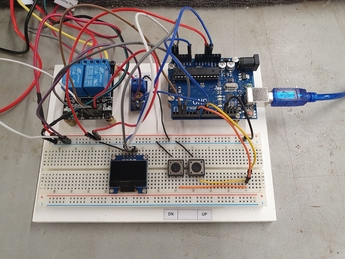
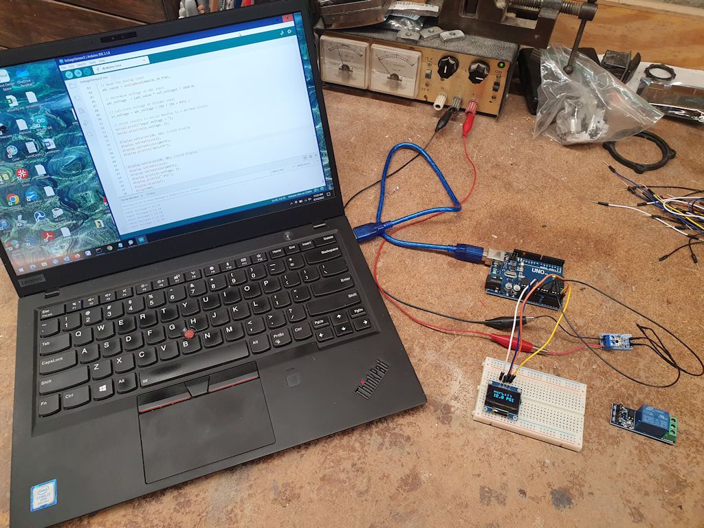
Science Experiment Step 1 was to check out the voltage sensor and the OLED display. In this photo, the Arduino microprocessor board is connected to the laptop through the blue USB cable; the source code is on the laptop screen and the USB cable both powers the microprocessor and provides for downloading the compiled code to the microprocessor. The voltage sensor is on the right and the display is at the bottom. The red and black clip leads are connected to a benchtop variable DC power supply so I can vary the input voltage to test everything. The relay that will control the compressor isn't connected yet, it's in the lower right of the photo.
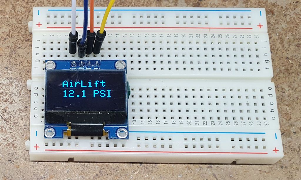
Everything checks out ok. For now, the display is showing the voltage from the benchtop power supply, and when the voltage output of the benchtop power supply is varied, the display tracks the changes. A closer look at the display:
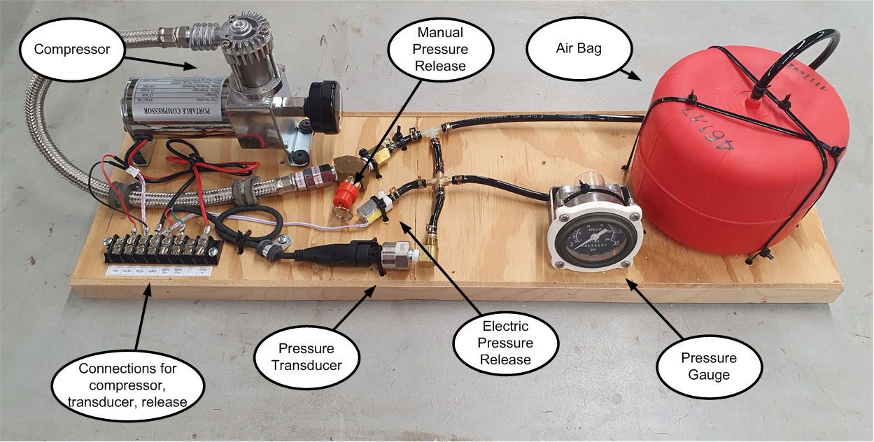
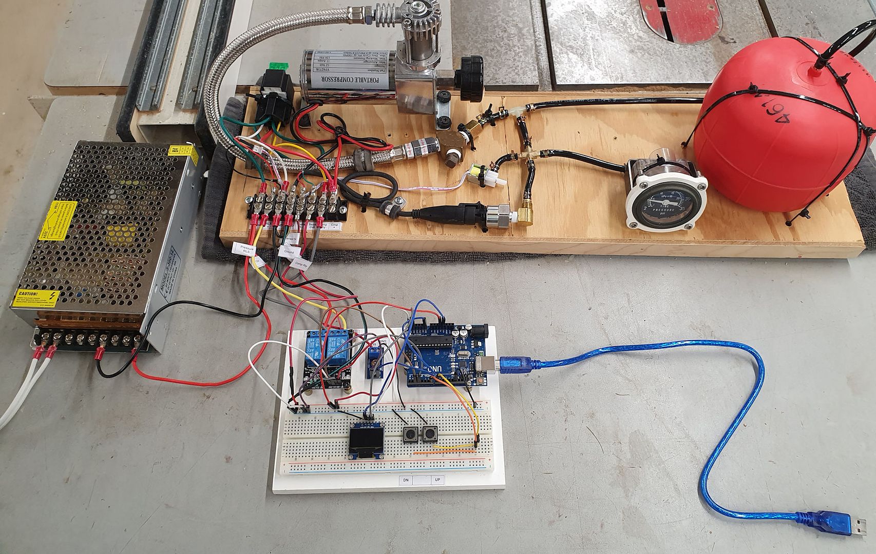
The next step is to change the code to convert the output voltage of the pressure transducer into PSI so the PSI can be displayed instead of voltage. Then connect the relay and write the code that will turn it on/off at appropriate times to control the pressure in the system. And once that's done I'll connect the compressor and the pressure transducer and hopefully watch the microprocessor control the compressor to manage the air bag pressure.

Everything checks out ok. For now, the display is showing the voltage from the benchtop power supply, and when the voltage output of the benchtop power supply is varied, the display tracks the changes. A closer look at the display:

The next step is to change the code to convert the output voltage of the pressure transducer into PSI so the PSI can be displayed instead of voltage. Then connect the relay and write the code that will turn it on/off at appropriate times to control the pressure in the system. And once that's done I'll connect the compressor and the pressure transducer and hopefully watch the microprocessor control the compressor to manage the air bag pressure.

